Holdoor DWB-10131 User manual

Holdoor
1
Holdoor Wireless IP Camera User Manual
Preface:
Dear customer,
Thank you for choosing to purchase and use our IP camera products. This series of IP monitoring
product is the integrated IP network camera which has been designed for network video
surveillance. The series includes a network bullet camera, a network IR bullet camera, and a
network dome camera. High performance, monolithic SOC chip is utilized as a media processor
which integrates video capture, compression, and transmission.
Standard H.264 main profile encoding algorithm ensures clear and smooth video transmission.
An embedded web server allows user to view real-time footage and remotely control the camera
via IE web browser. This series of IP camera is well-suited for home and small business, as well as
any situation which needs to apply remote network transmission and remote network control.
It's easy to install and operate.
Product Versions:
The content in this manual may be different from the product version you are using. If you meet
any problems which can't be solved according to this manual, please contact our technical
support or product supplier.
The content in this manual will be updated when necessary. Our company reserves the right to
update without notice.
Intended Reader:
This manual is intended for the following personnel: System planner
Onsite tech-support and maintenance personnel
Administrator for system installation, configuration and maintenance
Users for business operation on product functions
Terms in this Manual:
IP Camera, or IPC in this manual, means network camera including network bullet camera,
network dome camera, and network IR camera.
Click: Click with left button of mouse.
Double-click: Rapidly click the left mouse button twice.
Right-click: Click with the right button of mouse.
The [ ] symbol indicates the windows name, menu name, or data table; such as [Download
Address].

Holdoor
2
Contents
P2P Wireless IP Camera User Manual ........................................................................................1
1 Product Introduction..............................................................................................................3
1.1 Brief Introduction ........................................................................................................3
1.2 Main Features .............................................................................................................3
1.3 Installation Statement..................................................................................................3
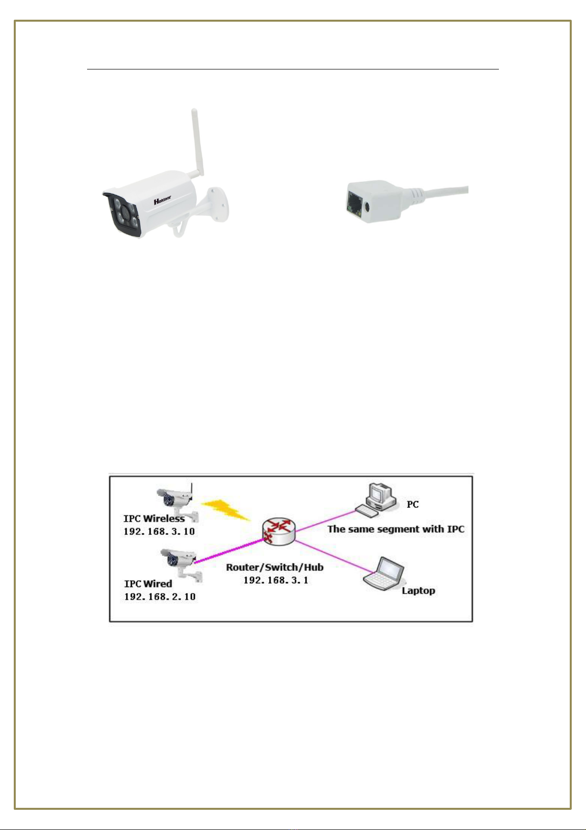
1.4 Network IP Camera Connection....................................................................................4
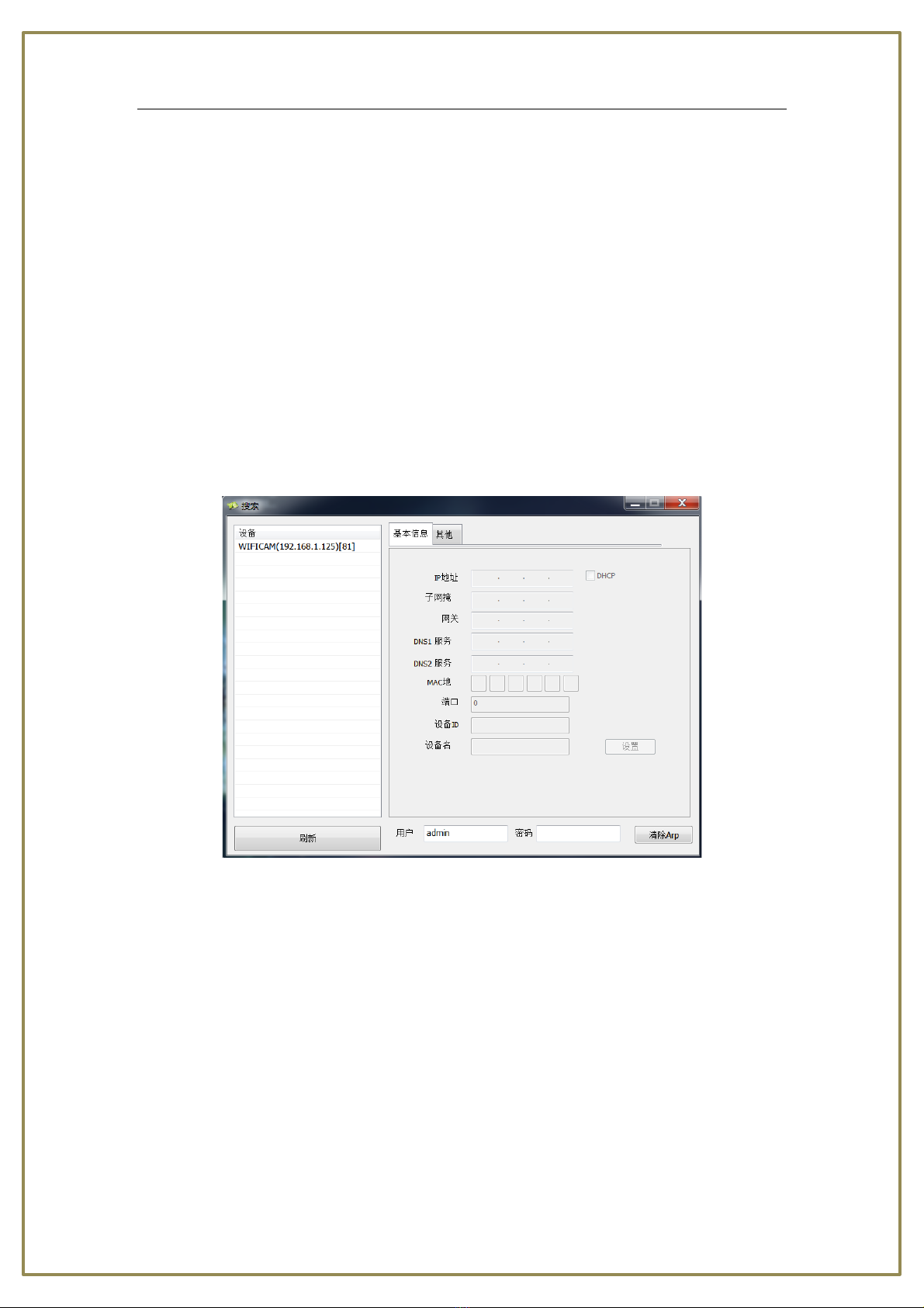
1 Install.............................................................................................................................4
2 Log In.............................................................................................................................5
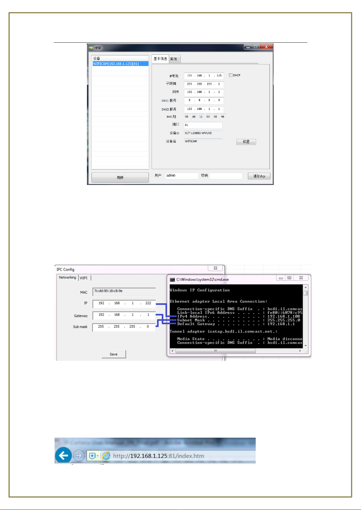
2.2 Network Configuration.................................................................................................6
2.3 Login...........................................................................................................................7
3 Preview .................................................................................................................................8
4 System Setting .....................................................................................................................11
4.1 Device basic information ...................................................................................................11
4.1.1 Device information ..........................................................................................11
4.1.2 Alias setting..................................................................................................11
4.1.3 Device date & Time Settings.............................................................................11
4.1.4 Local record path.............................................................................................12
4.1.5 SD Card Record Schdule...................................................................................12
4.2 Alarm Service Settings ...............................................................................................13
4.2.2 Mail service setting..........................................................................................14
4.2.3 FTP SERVICE SETTINGS.....................................................................................14
4.2.4 Alarm Log........................................................................................................15
4.3.1 Base Network Settings .....................................................................................16
4.3.2 Wireless Lan Settings .......................................................................................17
4.3.3 DDNS Configuration.........................................................................................18
4.4 PTZ ...........................................................................................................................19
4.5 USER & DEVICE..........................................................................................................19
4.5.1 Multi-Device....................................................................................................19
4.5.2 DEVICE USER SETTING .....................................................................................20
4.5.3 MAINTENANCE................................................................................................21
5Return..................................................................................................................................22
6 FAQ .....................................................................................................................................22
8. OBTAINING TECHNICAL SUPPORT.........................................................................................25

Holdoor
3
1 Product Introduction
1.1 Brief Introduction
This camera combines a traditional analog camera image sensor with a digital, IP based video
stream. The software is built off of an efficient Linux system with all code stored in flash memory.
This allows the camera to be small in size and extremely reliable.
1.2 Main Features
* Using only 8W, the camera will provide a 1280x720 resolution image at 25 frames per second
* Using H.264’s advanced video compression standard, the camera is capable of high
compression rates and flexible operation.
* Support two connection modes to internet, cable or wireless WiFi connection.
* A 1/4’’CMOS sensor provides fluid motion video with high -quality color.
* Automatic snapshots on alarm
* Dual stream with smart phone access
* Build-in web server supports access via Internet Explorer
* Support multiple user simultaneously, multi-level management ensures high system security.
* Support motion detection alarm (sensitivity configurable) and
* e-mail alert function
* Supports online system upgrade through the network.
* Automatic recovery functions when the system temporarily loses internet connection.
Support PPPOE, DDNS, LAN, and Internet (ADSL, Cable Modem)
1.3 Installation Statement
During installation and operation, please pay attention to the following items:
1. When you received the package product, please check the equipment and accessories
according to the packing list inside the shipping box.
2. Before installing the system, please carefully read this manual.
3. When you install the IP Camera, please make sure that it is not plugged into a power source.
4. Check the voltage of the power source to prevent damaging the device. The correct voltage is
12V DC and 1.5A.
Installation environment: Please do not use the cameras in an environment that has high
humidity, high temperature, or extreme changes in temperature. Make sure the camera is

Holdoor
4
installed in a location with good ventilation. Do not install the camera in an area that is subject to
violent vibrations.
Figure 1-1 Network IP Camera Figure 1-2 Camera Cable Ports
5. Outdoor Camera:
1). Lens: Default is 3.6mm (2.8mm, 6mm, 8mm, 12mm optional)
2). Infrared LED: 4 LEDs
3). Sensitive Hole
LAN: RJ-45/10-100 base T
Power: DC 12V/1.5A power supply
Network Light: The green LED will on when connect to the network, the yellow LED will blink
when data transferred
Original IPCAM have some stickers at the bottom, such as QR code UID user name PSW etc.
1.4 Network IP Camera Connection
Figure 1-3 Device Connection of Network IP Camera
1 Install
1: Connect the IP Camera to an open port in your router using a network LAN cable.
2: Connect the included power adapter to the IP Camera so that the camera powers on.
3: Go to www.holdoor.cn/ipcdisc and download the program called IP Camera Search Tool.
RJ45 network
Power

Holdoor
5
4:Search the IP address of the IPC
Open Search_tool, click ‘’Refresh’’, the IP address will be shown in the above window. Click the IP
address, you will see the networking details about this camera. Double click the IP address, the
links will be open by your default browser.
2 Log In
When using IE (Internet Explorer) to view the IP camera for the first time, you will have to set the
security level for ActiveX controls.
2.1 Set Security Levels
Open Internet Explorer, enter the IE Tools menu and go to Tools -->Internet Options --->Security
Settings ---->Custom Level. Find the item titled “Download unsigned ActiveX Controls” and
change it to “Prompt.” Also change “Initialize and script ActiveX controls not marked as safe for
scripting” to “Prompt.”
Figure 2-1 Security Level Setting
Install ActiveX and plugins:
1 Go to www.holdoor.cn/ipcdisc and download the OCX
2 Or type the network camera IP address (with port number) in the IE browser address bar, and
press [Enter] to bring up a dialog box , fill in user name ‘’admin’’, password ‘’none’’ (please input
nothing)to open the IE Client.
3 You also could open IPC Search tool and double click the IP of the IPC to open the IE Client.
4 Then you could download the OCX on IE.
5 Install the OCX.

Holdoor
6
2.2 Network Configuration
In order to login and view your camera from Internet Explorer, you will need to first find out the
IP Address Segment, Default Gateway, and Subnet Mask of your computer.
To find out the IP Address Segment, Default Gateway, and Subnet Mask, you will need to open
the command prompt from a Windows PC that is connected to the same router that your IP
Camera(s) will be connected to.
To open a Command Prompt, press the Windows Key and R at the same time on your keyboard.
Type "cmd" in the run line and press "Enter."
In the new window that appears, type "ipconfig" then press "Enter." Make note of your IPv4
Address, Subnet Mask, and Default Gateway. You will need this information later.
Open the program called Search_tool that you downloaded previously.
Click the [Refresh] button on the bottom left side of the Search tool program. Your IP Camera
should appear in the list of items if your IP Camera is successfully connected to the same router
as your PC is connected to.
Click on your IP Camera in the Search tool program, and you will have the option to change some
of the network settings:

Holdoor
7
In the Networking tab of the IPC Config menu, you will need to change the settings of the camera
to match your router settings:
In the IP field, type in the same IP address that appeared as the IPv4 Address on your ipconfig
results, but label the last three digits to a larger value such as 125.
In the Gateway field, type in the same numbers that appeared as the Default Gateway in your
ipconfig results.
In the Sub Mask field, type in the same numbers that appeared as the Subnet Mask on your
ipconfig results.
After adjusting all of these settings, click [Save]. The IP Address, Gateway, and Sub Mask should
update immediately after you click [Save]
2.3 Login
To view your IP Camera from Internet Explorer, open an Internet Explorer browser and type your
camera’s IP Address into the Internet Explorer browser as it appears in the Search tool program:

Holdoor
8
Please type the port number such as 192.168.1.125:81
Or double click the IP in the Search tool.
The Default Login Values are the Following:
User Name: admin
Password: ‘’none’’ (type it nothing)
When prompted by Internet Explorer to install add-ons, click [Yes] to install all add-ons.
Figure 2-2 Login Interface
3 Preview
After login the client, click ‘’livestream mode (for Internet Explorer)’’

Holdoor
9
Figure 3-1 Real-time Preview Interface
In the real-time preview interface, the user can control the video channel, record a short video,
take a snapshot, full-screen preview, image color, orientation, and PTZ control (if applicable).
[Single] Click the icon and there is only one channel on the window.
[Four] Click the icon and there are 4 channels on the window.

Holdoor
10
[Nine] Click the icon and there are 9 channels on the window.
[Record] Click the channel and then click the icon choose “record” check to start recording.
Remove “record” check to stop recording. The video is kept in file catalogue set by video capture.
[Capture] Click the channel and then click the icon “capture” to capture a still image of the
camera image. The capture photo is kept in catalog set by video capture.
[Setting] Click the channel and then click the icon ‘’setting’’ to set the camera.
[Modes] Click the channel then choose the mode. There have 4 type refresh rate. Indoor
50Hz; indoor 60Hz; outdoor 50Hz; outdoor 60Hz
[Resolution] Click the channel then choose the stream type (main-stream or sub-stream).
[Framerate] Click the channel then choose the Framerate type: 25, 20, 15, 10, 5
[Rate] Click the channel then choose the rate. Use the mouse to drag the slider to configure
these settings
[Full-screen preview] Double-click the image to view the full-screen preview. Double-click once
again to go back to the original image size.
[Image process] The image processing includes:
[Contrast]
[Brightness]
[Chroma] Sharpness adjustment
[Saturation] The image color can be set to either black and white or color.
[Mirror]The image orientation can be mirrored or reversed.

Holdoor
11
4 System Setting
4.1 Device basic information
4.1.1 Device information
The camera’s ID information and state information are in this page. You can change language as
Chinese or English.
4.1.2 Alias setting
This is the name of the video channel, and it is displayed on the upper left of the image. The
maximum number of characters for this field is 16. Click the check box, and it will display on the
screen. Un-check the check box, and it will not display the title on the screen.
4.1.3 Device date & Time Settings
You can choose time zone, date and time, and also you can choose the time format or sync with
PC time. It is recommended to leave it at the default.
After setting the date and time, click the [Set up] button, and the setting will take effect
immediately.

Holdoor
12
4.1.4 Local record path
[Local record path] Set file path for local recording and capture. After the file path is selected,
click the [Set up] button, and the configuration will take effect immediately.
[Record file length] This setting controls the length of the video files recorded.
[Record time length(Minute)] This setting controls the length of the video times recorded.
[Reserved disk space(MB)] This setting controls the length of reserved disk space
[Record cover] This setting controls record cover or not.
4.1.5 SD Card Record Schdule
This camera support TF Card up to 64GB, Recommend Sandisk Class 10 TF Card or surveillance
Special-purpose TF Card. Before using the TF card recording, please click [Format] to format the
memory card.
[Record coverage] If choose this, the video will be recording in the memory card over and over
again.
[Timer recording] The time will be recording on the video or picture on the upper right corner of
the video. Please set the camera time before using this feature.
[Select all] Choose this option, the memory card will record all the time. Also you can choose one
or parts of period. After the recording time is selected, click the [Set up] button, and the
configuration will take effect immediately.

Holdoor
13
4.2 Alarm Service Settings
4.2.1 alarm service setting
[Motion detect Alarm] Enable the time frame specified. If it is unchecked, the time frame is not
active. If it is checked, the motion detection time frame will be followed.
[Motion detect Sensitivity] The sensitivity of motion detection includes 10 levels: The smaller the
value, the more sensitive
[Send Alarm Notification by Mail] Set the appropriate action to take once motion is detected. An
e-mail can be sent to the e-mail specified in the e-mail section of 4.2.2. If no e-mail settings are
configured, then an e-mail will not be sent.
[Upload Image on Alarm] Set the appropriate action to take once motion is detected. A picture
can be send to you via ftp or email alarm.
[Upload picture number] 0~10 pictures can be set. If you fill it with 0, there will be not picture.
[Alarm recording] When alarm have been triggered, the 30-second video will record to memory
card.
[Alarm Arming Time] When the motion is detected, the alarm will work in the chosen period.

Holdoor
14
4.2.2 Mail service setting
It is the e-mail alert function which required linkage alarm to take effect.
If the camera triggers the alarm after configuring the mailbox parameter, it will send the alarm
message to email inbox.
[Sender] it is the sender email address, please fill out the complete mailbox information, for
example: test@gmail.com; “SMTP Server’’:
[SMTP PORT] SMTP server port, it will automatically be filled in once you selected the type of
SMTP SERVER.
[VERIFICATION] Some email servers need the user name and code to delivering the alarm email,
so turn on this feature.
[SSL]Mail encryption type, with both SSL and TLS, some mailbox providers support this type of
encrypted communications, such as: Gmail;
[SMTP USER] The user name of the sender mailbox, such as: test;
[SMTP CODE] The password for the mailbox of the sender.
[RECIPIENT] The email address for receiving alert messages, which can be the SENT mailbox.
Once completed the setup, click “test” button to check whether a mailbox is set to succeed.
Note: The camera should be connecting to the internet to get this feature, which need keeping
the correct password.
4.2.3 FTP SERVICE SETTINGS
Click the “FTP service settings”, appears below interface:

Holdoor
15
When motion is detected, this feature is primarily to snap a picture to upload to the directory
specified by the FTP server.
It need to access network (LAN) to make the setting.
[FTP SERVER] Fill in the current IP address of the FTP server.
[FTP PORT] The default value of 21, this port generally will not change which is determined
according to actual FTP server.
[FTP USER] FTP users;
[FTP PASSWORD] FTP user password;
Click “settings”, then the entry into force;
Click “test”, to test whether FTP was successful configured;
[Upload picture interval (seconds)]: Timing often automatically capture a picture to upload to the
FTP server in seconds;
The PC installed the software of FTP server can accordingly set up a test.
4.2.4 Alarm Log
Click ‘’alert log’’, appears below interface: which can view the alert log details:

Holdoor
16
4.3 Device Network Configuration
4.3.1 Base Network Settings
Click “Base Network Settings”: appears below interface:
[DHCP] If the router allows DHCP functionality, select DHCP to locate an un-used IP Address on
the router. After the camera is configured and is able to be viewed online, it is recommended to
keep DHCP disabled.
[IP Address] Set the wired cable IP address of IP camera device.
[Subnet mask] Default: 255.255.255.0 (It is recommended to not change the Subnet mask.)
[Gateway] Set the gateway IP of IPC. For example, if the IP Camera accesses a public network
through the router, the gateway IP needs to be the same as the router’s IP Address.
[MAC] The MAC address of the IP camera (It is recommended to not change the MAC address.)
[DNS address] If the user has a DDNS account, the DNS address needs to be set to the DNS
address of the place to which the device is assigned to in the DNS account.
After setting parameters, click the [Set up] button. The settings will take effect immediately.

Holdoor
17
4.3.2 Wireless Lan Settings
Figure 4-6 IPC WI-FI network setting
After enabling Wi-Fi, the camera will automatically search for wireless networks in the area.
When the camera is searching for a wireless network you will see the following information listed:
the name of the wireless router, signal intensity, and the encryption type.
This function can set the device to wireless mode, the device will restart when complete the
settings, you can unplug the cable once the device finished the Self Test.
[Using Wireless Lan] Select this checkbox to open the Wi-Fi network function of IPC.
[SSID] The name of the WiFi router.
[Network Type] Default: 255.255.255.0 (It is recommended to not change the Subnet mask.)
[Authetication] The encryption mode of the wifi router
[Share Key] The password of the wifi router

Holdoor
18
4.3.3 DDNS Configuration
[DDNS SERVER] Select DDNS Server;
[DDNS USER] Setting up DDNS username;
[DDNS PASSWORD] Setting up DDNS Password;
[DDNS DOMAIN NAME] Setting up DDNS Domain name;
To refresh it, once set succeed, DDNS will prompt state; The device’s IP needs to be done on the
router maps and mapping out the Net; Setting up successful, Copy the web site, Access through
the website, such as:
4.3.4 Docking NVR Function
NVR need to open the ONVIF and RTSP Streaming Protocol docking port, then set the port;
1ONVIF RELATED SETTINGS
Set the ONVIF Protocol ports open, then refresh and view to confirm the port is opened.
2. RTSP RELATED SETTINGS
Setup RTSP streaming ports is open, setup the port to 10554, then refresh and view to confirm
the RTSP state is opened.
The RTSP address is ‘’rtsp://ip:10554/tcp/av0_0’’, please replace ‘’ip’’ to camera’s ip address.

Holdoor
19
4.4 PTZ
Click the “PTZ SETTINGS” , appears below interface:
[Indicate light] Setting the LED to the state of turned on or off;
[Ban Preset] The preset function failure when enabled;
[Starts at the preset] 1~16 preset options, aligning the corresponding preset position when
startup the device; In forbidden state, the device to keep the power off before position after
startup.
[PTZ Speed] Adjust the PTZ speed;
[Number of Cruises] Set the number of cruises when start up vertical and horizontal, and it will
stop at ten minutes once you select “unlimited”;
Note: The PTZ is for the camera with ‘’PAN, TITL, ZOOM’’, if the camera have no PTZ, this setting is
invalid.
4.5 USER & DEVICE
4.5.1 Multi-Device
1.Click the “multi-channel Device Settings”, and Click “Refresh” to appears below interface, it can
set up to increase max 9-channel:

Holdoor
20
1. For example, add a second device: Click the “Second device”, and then select the current
local area network (in the same segment) exist in the device, the information will be
automatically obtained by the device, as shown in the following figure:
4.5.2 DEVICE USER SETTING
Click the “device user settings”, as follows:
Table of contents