Holman 4A91H Manual

Instruction Guide
4A91H
Holman
Rancho Cordova, CA 95742
800-343-7486
20201207R4 DATE: ______________

Instructions –4A91H
For Technical Support Call: 800-343-7486 Monday-Friday 7AM - 4 PM (PST) Page 2
*PLEASE READ ALL INSTRUCTIONS AND WARNINGS PRIOR TO ASSEMBLING,
INSTALLING, AND USING THIS PRODUCT*
Warning
Always check for wires, fuel tanks and lines, brake lines and other important vehicle
functionality items prior to drilling and installing all products.
Tools Needed
3/8”Socket and Wrench
1/2” Socket and Wrench
7/16” Socket and Wrench
Table of Contents
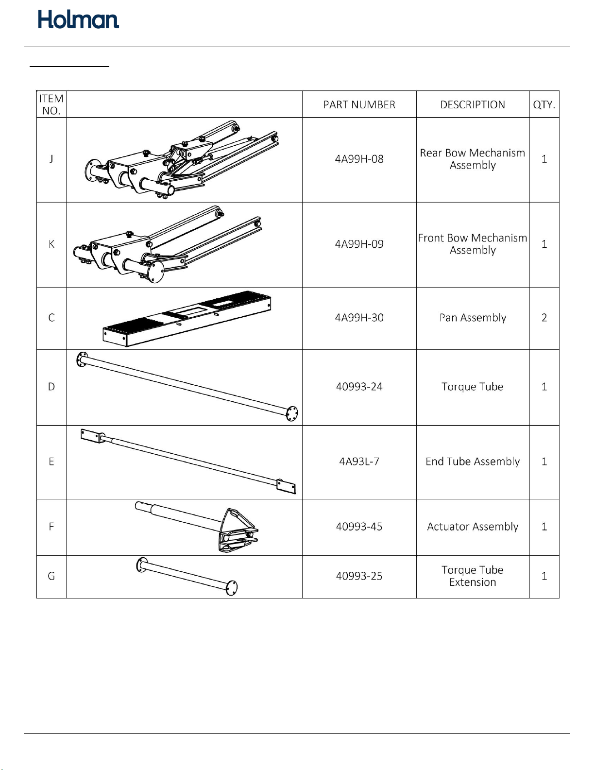
Parts List ...................................................................................................................................... 3-4
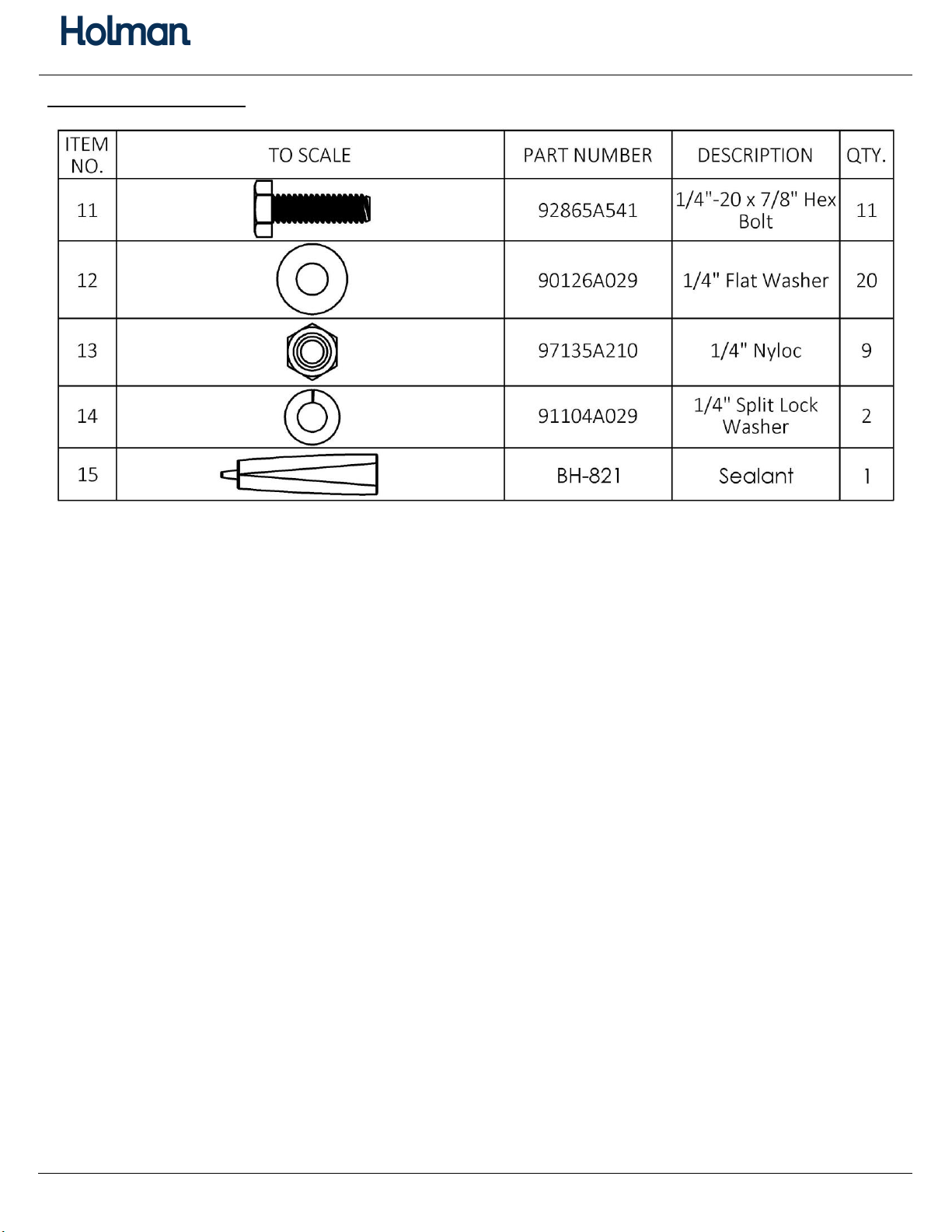
Hardware .................................................................................................................................... 5-6
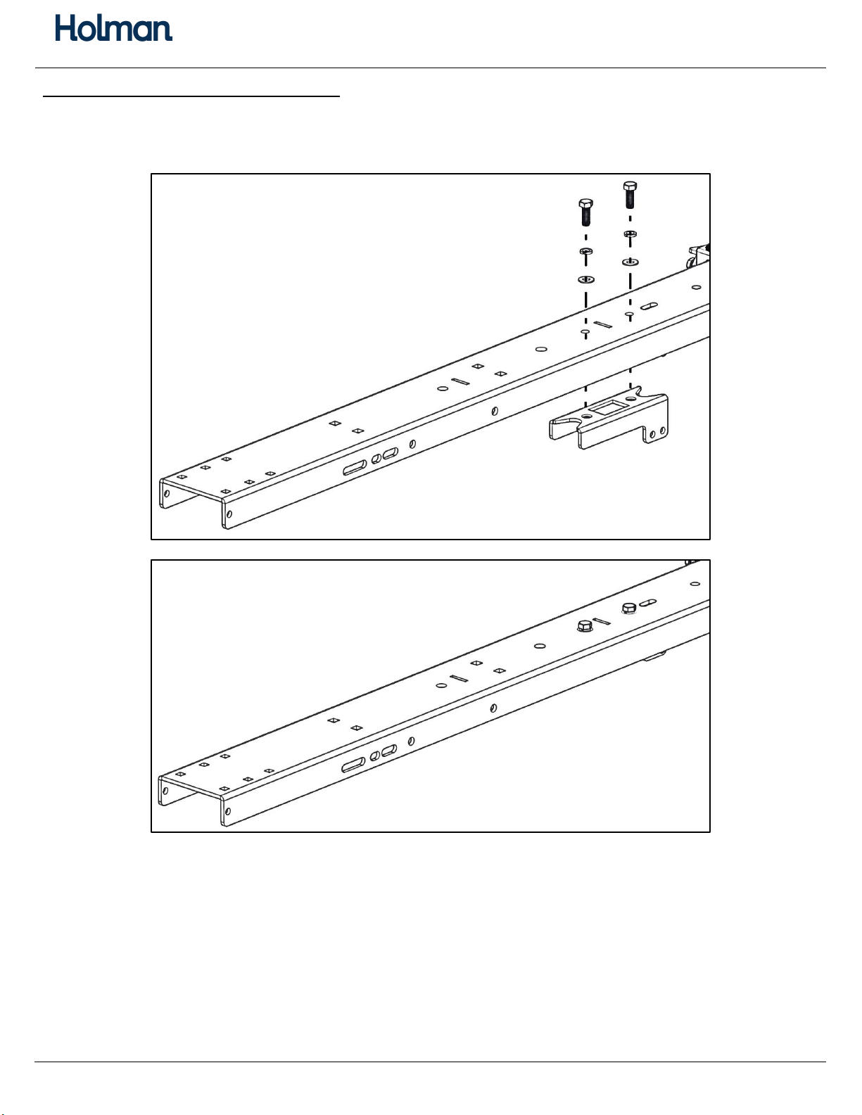
Step 1 –Assemble Front Bow ................................................................................................... 7-10
Step 2 –Install Spring on Front Bow .............................................................................................11
Step 3 –Assemble Rear Bow .................................................................................................. 12-14
Step 4 –Install Torque Tube .........................................................................................................15
Step 5 –Install End Tube ...............................................................................................................16
Step 6 –Install Actuator ................................................................................................................17
Step 7 –Install Gas Springs on Rear Bow ......................................................................................18
Step 8 –Install Ladder Hooks ........................................................................................................19
Step 9 –Install Ladder Stops .........................................................................................................20
Step 10 –Test Ladder Rack ...........................................................................................................21
Before You Begin
Read all instructions.
This kit is a driver side add on. A ladder rack must be assembled prior to installation of this
kit.
DO NOT EXCEED MANUFACTURERS WEIGHT CAPACITY FOR ROOF.

Instructions –4A91H
For Technical Support Call: 800-343-7486 Monday-Friday 7AM - 4 PM (PST) Page 3
Parts 1 of 2

Instructions –4A91H
For Technical Support Call: 800-343-7486 Monday-Friday 7AM - 4 PM (PST) Page 4
Parts 2 of 2

Instructions –4A91H
For Technical Support Call: 800-343-7486 Monday-Friday 7AM - 4 PM (PST) Page 5
Hardware (1 of 2)

Instructions –4A91H
For Technical Support Call: 800-343-7486 Monday-Friday 7AM - 4 PM (PST) Page 6
Hardware (2 of 2)

Instructions –4A91H
For Technical Support Call: 800-343-7486 Monday-Friday 7AM - 4 PM (PST) Page 7
Step 1 –Assemble Front Bow
Attach the spring mount to the underside of the front bow using the pre-assembled
hardware in the location and orientation shown. (picture shown without mounting feet for
clarity)

Instructions –4A91H
For Technical Support Call: 800-343-7486 Monday-Friday 7AM - 4 PM (PST) Page 8
Remove the 3/8”
hardware from the front
bow mechanism as
shown.
Note: This is the mechanism with NO
gas springs.
Attach the front bow
mechanism to the
underside of the front
bow using the previously
removed 3/8” hardware
in the locations shown.
TIGHTEN.
Insert a rubber bumper in
the round hole as shown.
The large end of the
bumper goes on top of
the bow.
Slide a wheel axle into the hole at the end of each bow.
Place a nylon washer at each end of the axle on the outside of the bow.
Install a wheel at each end of the axle. Cap each wheel with a wheel cap.
**WHEN INSTALLING THE PAN, BE SURE THE WHEEL CAPS STAY IN PLACE**

Instructions –4A91H
For Technical Support Call: 800-343-7486 Monday-Friday 7AM - 4 PM (PST) Page 9
Rotate the pan perpendicular to the top bow
and at a slight angle as shown.
Manuever the pan around the wheels.
Ensure the wheels are contained inside the pan
and lay the pan on top of the bow.
**BE SURE THE WHEEL CAPS DID NOT COME OFF**

Instructions –4A91H
For Technical Support Call: 800-343-7486 Monday-Friday 7AM - 4 PM (PST) Page 10
Remove the
hardware that is pre-
assembled in the pan
assembly (pictures
shown without the
bow for clarity).
Place the nylon spacer in between the pan and the arm on both sides.
The nylon washer goes against the outside of each arm.
Align the arms from the mechanism assembly with the holes in the pan. Reinstall the
previously removed hardware in the orientation shown.
Do not over tighten. The pan and the arm are designed to rotate against each other.
Nylon Spacer
Nylon Washer

Instructions –4A91H
For Technical Support Call: 800-343-7486 Monday-Friday 7AM - 4 PM (PST) Page 11
Step 2 –Install Spring on Front Bow
Install the spring on the underside of the front bow by attaching one end of the spring to
the spring mount and the other end of the spring to the front bow mechanism.
Hook the spring onto the pin in the spring mount bracket (shown without the bow for
clarity).
Pivot the pan to adjust the mount on the
mechanism.
Stretch the spring and hook onto the mount
on the front pan mechanism. Return the pan
in the down position.

Instructions –4A91H
For Technical Support Call: 800-343-7486 Monday-Friday 7AM - 4 PM (PST) Page 12
Step 3 –Assemble Rear Bow
Remove the 3/8”
hardware in the rear
bow mechanism as
shown.
Note: This is the mechanism with
the gas springs.
Attach the rear bow
mechanism to the
underside of the rear
bow using the
previously removed
3/8” hardware in the
locations shown.
TIGHTEN.
Insert a rubber bumper
in the slot as shown. The
large bumper goes on
top of the bow.
Slide a wheel axle into
the hole at the end of each bow.
Place a nylon washer at each end of the axle on the outside of the bow.
Install a wheel at each end of the axle. Cap each wheel with a wheel cap.
**WHEN INSTALLING THE PAN, BE SURE THE WHEEL CAPS STAY IN PLACE**

Instructions –4A91H
For Technical Support Call: 800-343-7486 Monday-Friday 7AM - 4 PM (PST) Page 13
Rotate the pan perpendicular to the top bow
and at a slight angle as shown.
The pan needs to be manuevered around the
wheels.
Ensure the wheels are contained inside the pan
and lay the pan on top of the bow.
**BE SURE THE WHEEL CAPS DID NOT COME OFF**

Instructions –4A91H
For Technical Support Call: 800-343-7486 Monday-Friday 7AM - 4 PM (PST) Page 14
Remove the
hardware that is pre-
assembled in the pan
assembly (pictures
shown without the
bow for clarity).
Place the nylon spacer in between the pan and the arm on both sides.
The nylon washer goes against the outside of each arm.
Align the arms from the mechanism assembly with the holes in the pan. Reinstall the
previously removed hardware in the orientation shown.
Do not over tighten. The pan and the arm are designed to rotate against each other.
Nylon Spacer
Nylon Washer

Instructions –4A91H
For Technical Support Call: 800-343-7486 Monday-Friday 7AM - 4 PM (PST) Page 15
Step 4 –Install Torque Tube
Determine if the torque tube extension will be needed. Look at the passenger side for
reference. The picture shown below shows the rack with the tube extension installed.
Note: The extension is being used in the pictures.
Bolt the torque tube to the front and rear bow using 1/4" x 7/8” hex head bolts, 1/4" flat
washers and 1/4" nyloc nuts. Repeat this process if the extension is being used.
Snug tighten, but allow movement.

Instructions –4A91H
For Technical Support Call: 800-343-7486 Monday-Friday 7AM - 4 PM (PST) Page 16
Step 5 –Install End Tube
Bolt the end tube assembly to the end of the pan on the front and rear bow using 5/16" x
3/4” hex head bolts, 5/16” lock washers and 5/16" flat washers.
Snug tighten, but allow movement.

Instructions –4A91H
For Technical Support Call: 800-343-7486 Monday-Friday 7AM - 4 PM (PST) Page 17
Step 6 –Install Actuator
Remove the hardware, as shown, from the tube on the rear bow.
Insert actuator extension into the tube and attach using the previously removed hardware.
Insert actuator assembly into the end of the actuator extension as shown below.
Bolt into place using two 5/16” x 1-3/4” hex head bolts, four 5/16” flat washers and two
5/16” nyloc nuts.
Tighten.

Instructions –4A91H
For Technical Support Call: 800-343-7486 Monday-Friday 7AM - 4 PM (PST) Page 18
Step 7 –Install Gas Springs on Rear Bow
Remove the pin, spacer and the nylon
washers that are pre-assembled in-
between the gas springs from the rear
bow mechanism.
Rotate the pan to a position so the mounts on the mechanism will allow the gas springs to
be installed.
Use the pin, spacers and the nylon washers that were removed to attach the gas springs to
the gas spring mount on the underside of the rear bow. The spacer goes in between the
two gas springs. The nylon washers go in between the gas springs and the mount.
Note: In some situations, these gas springs can be installed easier by using the handle to help pivot the pan. The
orientation of the gas springs may vary.

Instructions –4A91H
For Technical Support Call: 800-343-7486 Monday-Friday 7AM - 4 PM (PST) Page 19
Step 8 –Install Ladder Hooks
Assemble the ladder hooks.
Note: This can be adjusted at a later time to
better fit the size of the ladder being used.
Bolt together using 1/4" x 7/8”
hex head bolt, 1/4" lock
washer and a 1/4" flat washer.
Repeat for a second ladder
hook.
Tighten.
Place one ladder hook assembly onto the front bow and one ladder hook on the rear bow.
There are two threaded studs to choose from on each bow. The ladder being used on the
ladder rack will determine which location is used.
Bolt into place using the pre-assembled hardware on both front and rear pan.

Instructions –4A91H
For Technical Support Call: 800-343-7486 Monday-Friday 7AM - 4 PM (PST) Page 20
Step 9 –Install Ladder Stop
Find the slot and the installed hardware
near the previously installed ladder hook
assembly.
Remove the hardware in the bow and
place the ladder stop in that location. Bolt
into place using the removed hardware.
Be sure the tab on the ladder stop aligns
with the slot in the bow.
Repeat on each bow.
Tighten.
Table of contents
Other Holman Automobile Accessories manuals