Holman 4A822 Manual

!
Instruction Guide
4A822
Holman
Rancho Cordova, CA 95742
800-343-7486
InstallationSupport@Holman.com
20201105R3 DATE: ______________

For Technical Support Call: 800-343-7486 Monday-Friday 7AM - 4 PM (PST) Page 1
Instructions – 4A822
* PLEASE READ ALL INSTRUCTIONS AND WARNINGS PRIOR TO
ASSEMBLING, INSTALLING, AND USING THIS PRODUCT. *
Warning
Always check for wires, fuel tanks and lines, brake lines and other important vehicle
functionality items prior to drilling and installing all products.
Tools Needed
9/16” Socket and Wrench
7/16” Socket and Wrench
13mm Socket and Wrench
10mm Socket and Wrench
Table of Contents
Before You Begin ................................................................................................................... 1
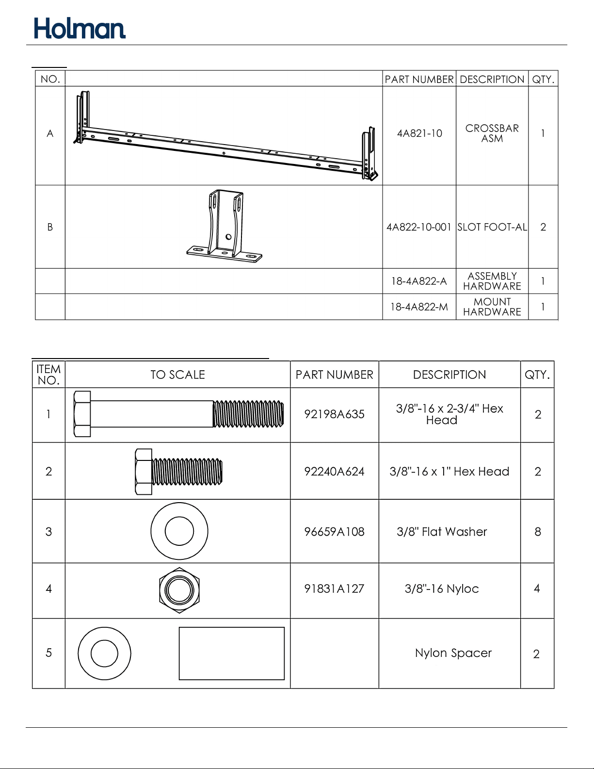
Parts ...................................................................................................................................... 2
Assembly Hardware (18-4A822-A) ........................................................................................ 2
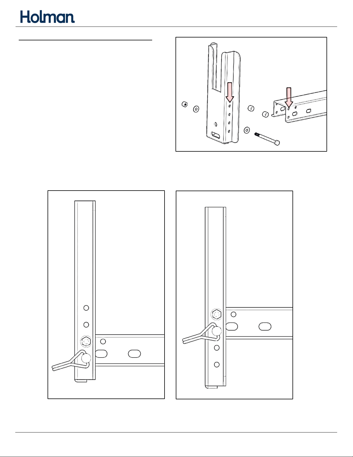
Step 1 – Adjustment of Uprights ........................................................................................... 3
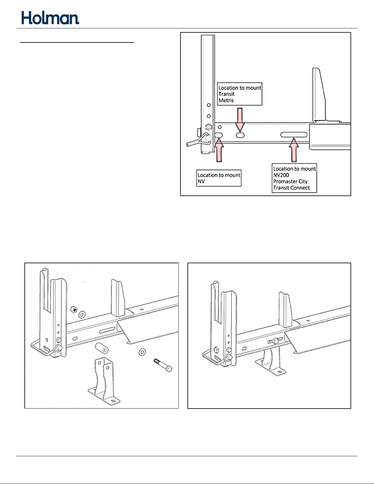
Step 2 – Assembly of Foot ..................................................................................................... 4
Installation Instructions
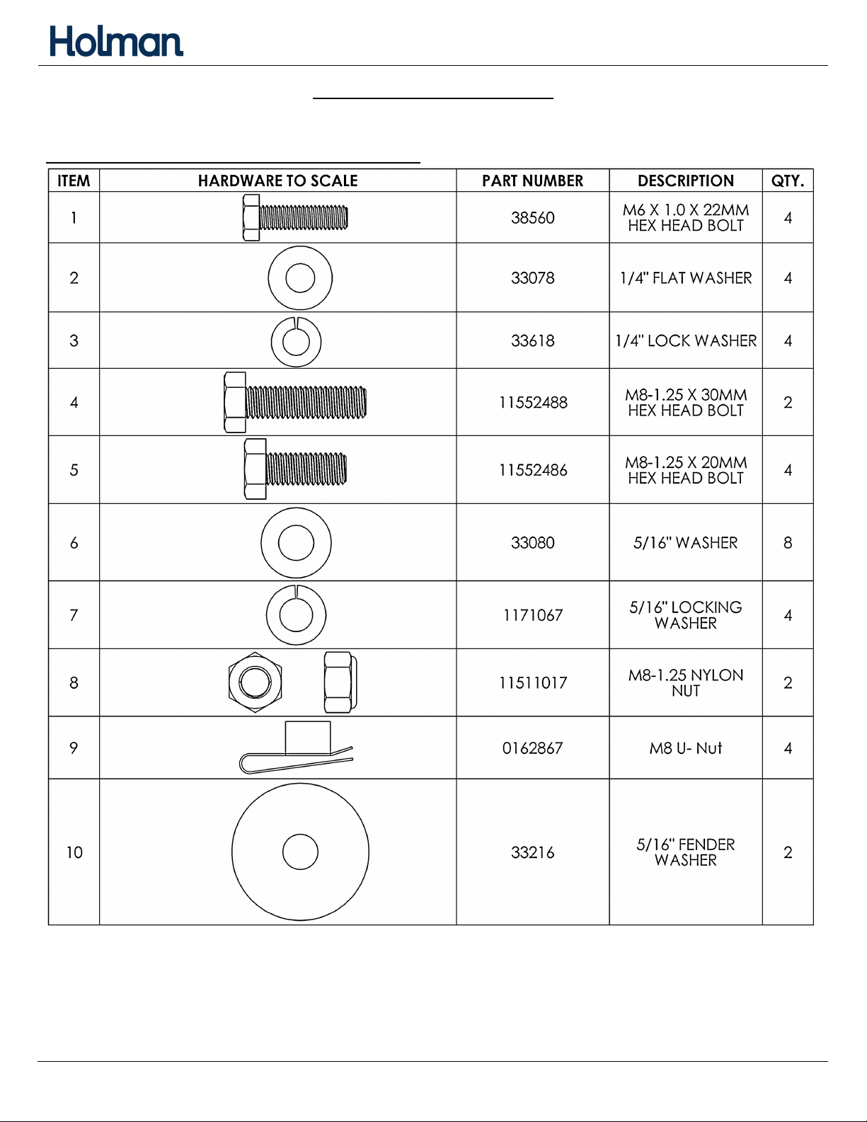
Installation Hardware (To Scale) (18-4A821-M) ................................................................. 5
Transit Connect ................................................................................................................... 7
Transit ................................................................................................................................. 8
ProMaster City .................................................................................................................... 9
NV200/Chevy City Express ................................................................................................ 10
Metris ............................................................................................................................... 11
NV ..................................................................................................................................... 12
Before You Begin
• Read all instructions.
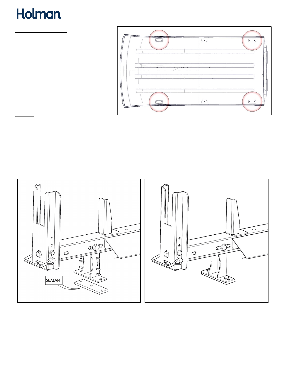
• Be sure to put sealant around all threads entering cargo area and between the rubber
spacer and roof of vehicle to prevent water from leaking into cargo area.
• Ensure ALL hardware is tight at the conclusion of the instructions.

For Technical Support Call: 800-343-7486 Monday-Friday 7AM - 4 PM (PST) Page 2
Instructions – 4A822
Parts
Assembly Hardware (18-4A822-A)

For Technical Support Call: 800-343-7486 Monday-Friday 7AM - 4 PM (PST) Page 3
Instructions – 4A822
Step 1 – Adjustment of Uprights
• The uprights at each end of the crossbar
come preinstalled.
• If van upright is not at desired height,
remove bolts and adjust accordingly. Be
sure to have one hole open below where
van upright is bolted to cross member.
• Repeat on other side of cross member.
• Insert pin through the van upright and the
cross member, using the open hole below
the previously installed hex bolt.
• TIGHTEN.
Below shows different heights of van uprights

For Technical Support Call: 800-343-7486 Monday-Friday 7AM - 4 PM (PST) Page 4
Instructions – 4A822
Step 2 – Assembly of Foot
• Depending on your vehicle, the foot will
mount in different slots.
• Use a 3/8" x 2-3/4" hex head bolt, two 3/8" flat washers, and a 3/8" lock nut to bolt foot (B)
to cross member (A). Be sure to insert the nylon spacer inside foot.
• Have the cup in the foot facing outward, as shown.
• Do NOT tighten.
• Repeat on opposite side.
For installation, follow your vehicles instructions below.

For Technical Support Call: 800-343-7486 Monday-Friday 7AM - 4 PM (PST) Page 5
Instructions – 4A822
Installation Instructions
• Find vehicle below, follow instructions from there.
Installation Hardware (18-4A822-M)

For Technical Support Call: 800-343-7486 Monday-Friday 7AM - 4 PM (PST) Page 6
Instructions – 4A822
Installation Hardware (Continued)

For Technical Support Call: 800-343-7486 Monday-Friday 7AM - 4 PM (PST) Page 7
Instructions – 4A822
Transit Connect
Step 1
• Locate 2 mounting
locations in roof for the
crossbar to be installed.
• Remove plug
from desired mounting
locations in roof.
Step 2
• Bolt through the mount foot (B) into the exposed holes in roof using one M8 x 30mm hex
head, one 5/16” flat washer, a rubber spacer, a rubber washer, one 5/16” fender washer,
and one M8 lock nut, in the order shown.
• Be sure to put a rubber spacer in between mount foot (B) and roof of van as shown below.
• The roof goes in between rubber spacer and rubber washer.
• Place sealant between rubber spacer and roof of van and around threads to ensure no water
leaks into van.
• Repeat for opposite side.
Step 3
• Go back and tighten all hardware including hardware on the rack itself.

For Technical Support Call: 800-343-7486 Monday-Friday 7AM - 4 PM (PST) Page 8
Instructions – 4A822
Transit
Step 1
• Locate 2 mounting
locations on roof for
the crossbar to be
installed.
• Remove plug
from desired
mounting locations in
roof.
Step 2
• Bolt through the mount foot (B) into the exposed holes in roof using one M8 x 30mm hex
head, one 5/16” lock washer, one 5/16” flat washer, a metal plate, and a rubber pad, in the
order shown.
• Be sure to put rubber pad and metal plate in between mount foot (B) and roof of van as
shown below. The rubber pad goes on the roof.
• Place sealant between rubber pad and roof of van and around threads to ensure no water
leaks into van.
• Repeat for opposite side.
Step 3
• Go back and tighten all hardware including hardware on the rack itself.

For Technical Support Call: 800-343-7486 Monday-Friday 7AM - 4 PM (PST) Page 9
Instructions – 4A822
ProMaster City
Step 1
• Locate 2 mounting locations on
roof for the crossbar to be
installed.
• Remove plug from desired
mounting locations in roof.
Step 2
• Bolt through the mount foot (B) into the exposed holes in roof using one M6 x 22mm hex
head, one 1/4” lock washer, one 1/4” flat washer, and a rubber spacer, in the order shown.
• Be sure to put a rubber spacer in between mount foot (B) and roof of van as shown below.
• Place sealant between rubber spacer and roof of van and around threads to ensure no water
leaks into van.
• Repeat for opposite side.
Step 3
• Go back and tighten all hardware including hardware on the rack itself.

For Technical Support Call: 800-343-7486 Monday-Friday 7AM - 4 PM (PST) Page 10
Instructions – 4A822
NV200/Chevy City Express
Step 1
• Locate 2 mounting locations on
roof for the crossbar to be
installed.
• Remove plug from desired
mounting locations in roof.
Step 2
• Bolt through mount foot (B) into the exposed holes in roof using one M8 x 30mm hex head,
one 5/16” lock washer, one 5/16” flat washer, and a rubber washer, in the order shown.
• Be sure to put a rubber washer in between mount foot (B) and roof of van as shown below.
• Place sealant between rubber spacer and roof of van and around threads to ensure no water
leaks into van.
• Repeat for opposite side.
Step 3
• Go back and tighten all bolts including nuts and bolts on the rack itself.

For Technical Support Call: 800-343-7486 Monday-Friday 7AM - 4 PM (PST) Page 11
Instructions – 4A822
Metris
Step 1
• Locate 2 mounting locations
on roof for the crossbar to be
installed.
• Remove plug from desired
mounting locations in roof.
Step 2
• Bolt through the mount foot (B) into the exposed holes in roof using one M6 x 22mm hex
head, one 1/4” lock washer, one 1/4” flat washer, and a rubber spacer, in the order shown.
• Be sure to put a rubber spacer in between mount foot (B) and roof of van as shown below.
• Place sealant between rubber spacer and roof of van and around threads to ensure no water
leaks into van.
• Repeat for opposite side.
Step 3
• Go back and tighten all hardware including hardware on the rack itself.

For Technical Support Call: 800-343-7486 Monday-Friday 7AM - 4 PM (PST) Page 12
Instructions – 4A822
NV
Step 1
• Locate 2 mounting locations
on roof for the crossbar to
be installed.
Step 2
• Install M8 U-Nuts as shown.
Step 3
• Bolt through the mount foot (B) into the previously installed M8 U-nuts using
M8 x 20mm hex head, 5/16” lock washer, and 5/16” flat washer.
Step 4
• Repeat previous steps on opposite side.
• Go back and tighten all hardware including hardware on the rack itself.
Table of contents
Other Holman Automobile Accessories manuals