Holman 12004 User manual

Instructions –PRO Forklift Service Body Rack
For Technical Support Call: 800-343-7486, Monday-Friday, 7AM - 4 PM (PST) Page 1
PLEASE READ ALL INSTRUCTIONS AND WARNINGS PRIOR TO
ASSEMBLING, INSTALLING, AND USING THIS PRODUCT.
WARNING
Always check for wires, fuel tanks and lines, brake lines and other important
vehicle functionality items prior to drilling and installing all products.
Too much weight will greatly reduce the stability of your vehicle. Holman makes
no representation or warranty as to the amount of weight your vehicle can
safely carry. For guidance, we recommend that you consult the vehicle
manufacturer. At no time should the weight of the vehicle, rack, driver,
passengers and cargo loaded on a Holman rack exceed either the Gross
Vehicle Weight Ratio (GVWR) or the Gross Axle Weight Ratio (GAWR) as
specified by the vehicle manufacturer.
Do not use your rack with the rear cross bar removed. Removal of rear crossbar
will affect structural integrity of the rack.
Secure all payloads properly for safe transportation.
Tools Needed
1/2” 9/16”, 3/4” Box Wrenches
1/2”, 9/16”, 3/4” Sockets and Wrench
7/32”, 5/16” Allen Wrenches
Drill
11/32”, 13/32” Drill Bits
Drill Bit Stop Collar
Before You Begin
1. Read all instructions carefully, and follow each step in proper sequence, for ease and
speed in assembling your Holman rack.
2. The “bulkhead” is the panel at the front of the service body. Measure the distance from the
top of the bulkhead to the top of the truck’s cab. This distance should be in the range of
15” to 22”.
3. PROPER SEALANT APPLICATION IS CRITICAL TO PREVENTING WATER PENETRATION
INSIDE THE RACK. Apply a healthy bead of sealant entirely around every swaged joint and
every bolt going through tubing. Improper sealing can lead to water penetration and rust
on inside surfaces.

Instructions –PRO Forklift Service Body Rack
For Technical Support Call: 800-343-7486, Monday-Friday, 7AM - 4 PM (PST) Page 2
4. Standard mounting is on the rear panel. Check to ensure the rear panel of the service body
is free of taillights or other obstructions (inside or out) in the area where the rear legs of
the rack bolt to the body. Consult sketch below.
a. There must be open unobstructed space at least 1-3/4” above taillight and below flip
top box lid.
b. There must be open unobstructed space at least 1-1/4” to the left or right of taillight.
c. The distance between the crown of the roof plus 2-1/2” to the top of the mount bracket
must be no greater than 24-1/2”. If the distance is greater than 24-1/2”, the optional
9” extension kit (31520) is required.
d. The service body foot must be mounted as close as possible to the vertical exterior
corner of the rear body panel. If mounting to the vertical exterior corner of the rear
body panel is not possible, the right and left service body rear feet can be switched
and the feet can be mounted as close as possible to the vertical interior corner of the
rear body panel.

Instructions –PRO Forklift Service Body Rack
For Technical Support Call: 800-343-7486, Monday-Friday, 7AM - 4 PM (PST) Page 3

Instructions –PRO Forklift Service Body Rack
For Technical Support Call: 800-343-7486, Monday-Friday, 7AM - 4 PM (PST) Page 4
Table of Contents
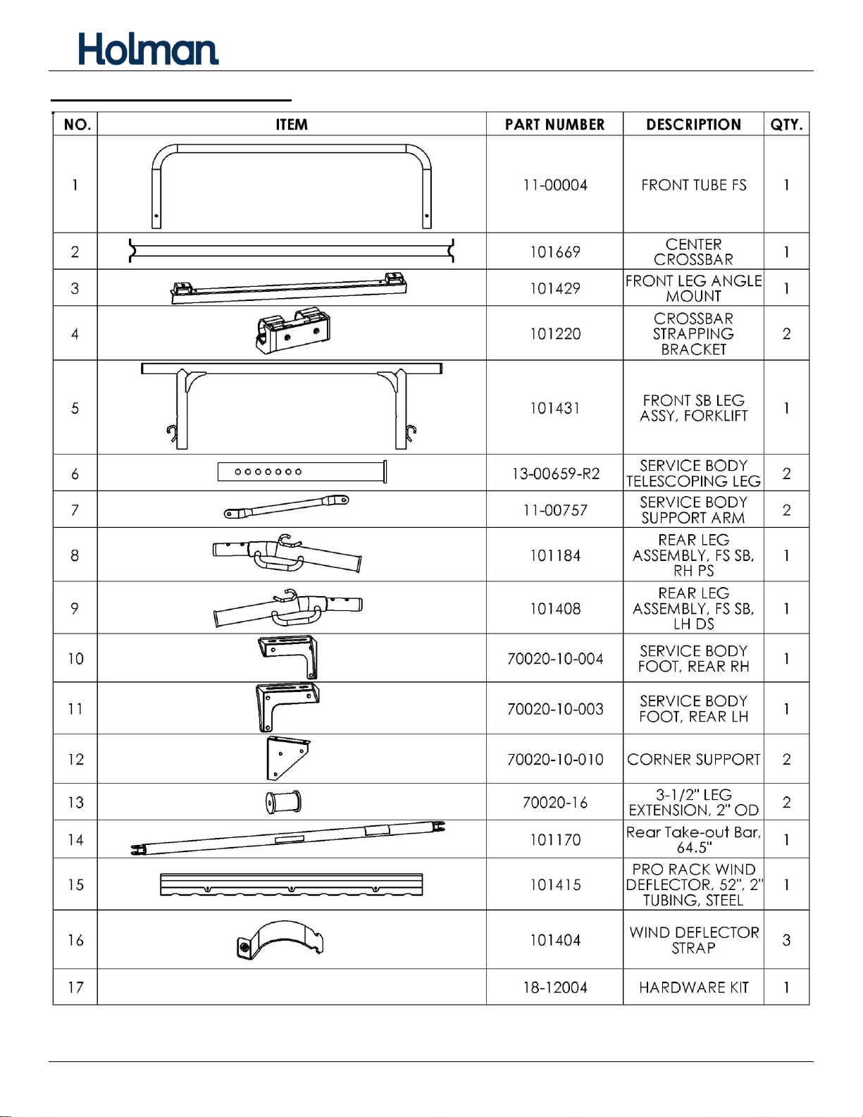
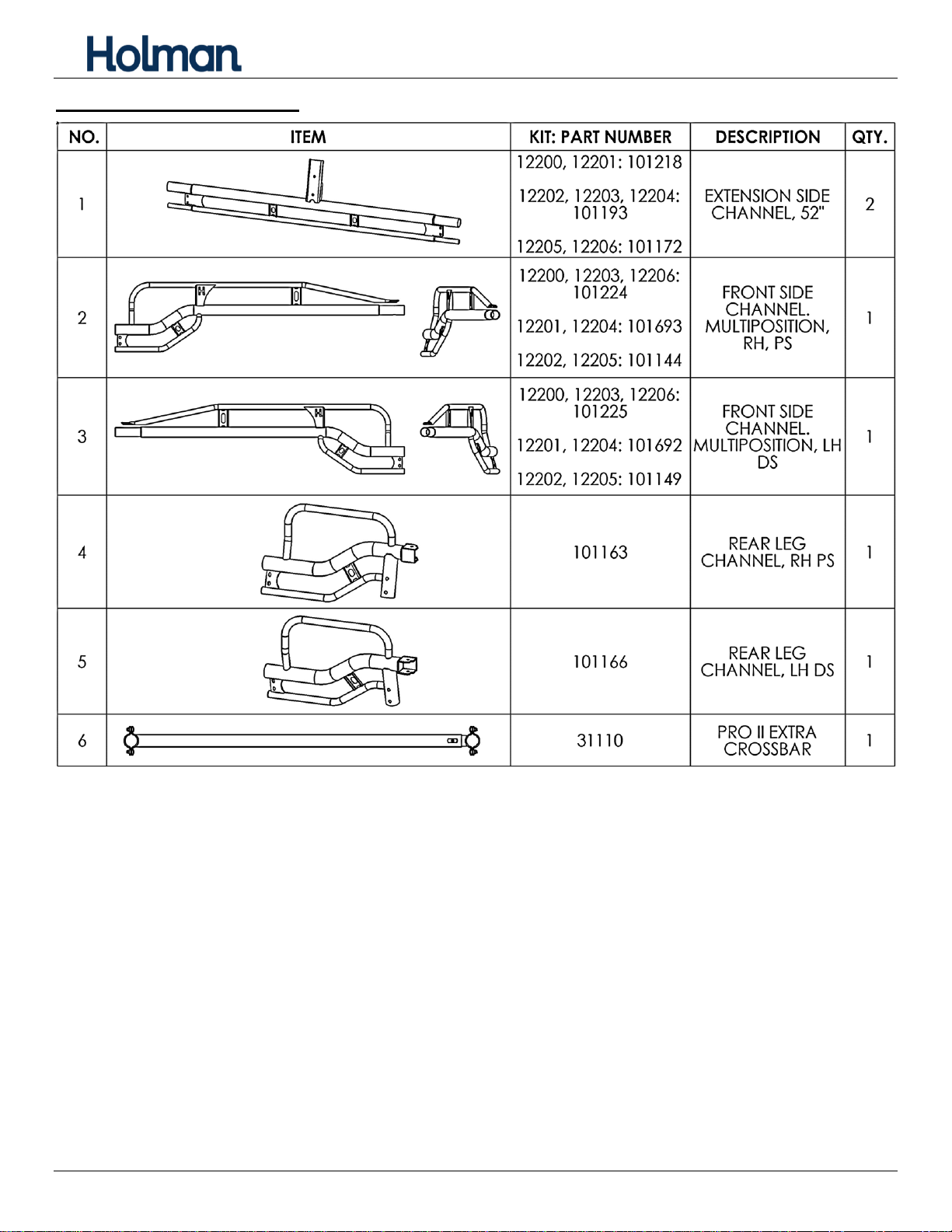
Leg and Bar Kit Parts List................................................................................................................5
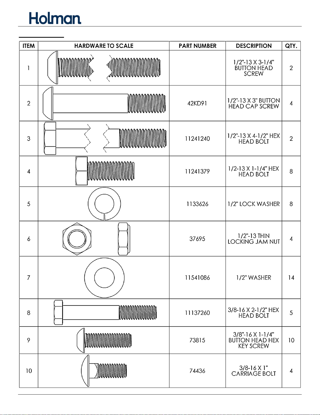
Hardware Kit....................................................................................................................................7
Hardware (Continued) .....................................................................................................................8
Sealant Application..........................................................................................................................9
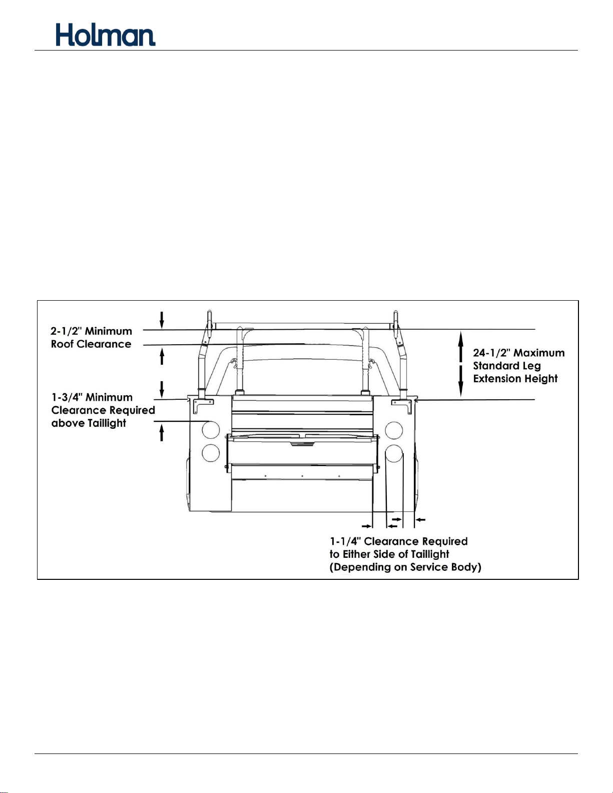
Step 1 –Measure Service Body and Truck .....................................................................................9
Step 2 –Install Front Leg Angle Mount .........................................................................................10
Step 3 –Install Bulkhead Bracing..................................................................................................10
Step 4 –Assemble Front Leg Assembly........................................................................................11
Step 5 –Join Side Channels .........................................................................................................11
Step 6 –Attach Wind Deflector......................................................................................................12
Step 7 –Attach Front Tube............................................................................................................13
Step 8 –Attach Center Crossbar...................................................................................................13
Step 9 –Attach Rear Take-out Bar................................................................................................13
Step 10 –Attach Rear Legs...........................................................................................................14
Step 11 –Attach Front Legs..........................................................................................................14
Step 12 –Install Foot to Rack........................................................................................................16
Step 13 –Install Rack onto Service Body......................................................................................17
Step 14 –Install Support Arm........................................................................................................18
Step 15 –Tighten Hardware..........................................................................................................18
Troubleshooting.............................................................................................................................19
Rear Take-out Bar Position Lock...................................................................................................19
Adjust Wind Deflector....................................................................................................................19
Install Extra Crossbar ....................................................................................................................20

Instructions –PRO Forklift Service Body Rack
For Technical Support Call: 800-343-7486, Monday-Friday, 7AM - 4 PM (PST) Page 5
Leg and Bar Kit Parts List

Instructions –PRO Forklift Service Body Rack
For Technical Support Call: 800-343-7486, Monday-Friday, 7AM - 4 PM (PST) Page 6
Side Channel Parts List
* Extra crossbar is included in extended and crew cab kits only.
*

Instructions –PRO Forklift Service Body Rack
For Technical Support Call: 800-343-7486, Monday-Friday, 7AM - 4 PM (PST) Page 7
Hardware Kit

Instructions –PRO Forklift Service Body Rack
For Technical Support Call: 800-343-7486, Monday-Friday, 7AM - 4 PM (PST) Page 8
Hardware (Continued)

Instructions –PRO Forklift Service Body Rack
For Technical Support Call: 800-343-7486, Monday-Friday, 7AM - 4 PM (PST) Page 9
Sealant Application
Proper sealant application is critical to preventing water penetration inside the
rack.
Apply a healthy bead of sealant around every swaged joint as shown. Improper sealing can lead
to water penetration and rust on inside surfaces.
Wipe any excess sealant off immediately with a plastic scraper or paper towel. Any smeared
sealant can be rubbed off as soon as sealant dries.
Maintain this seal throughout the life of your rack.
Repeat process for opposite side.
Step 1 –Measure Service Body and Truck
Measure distance between inside of service body bulkhead to rear of service body.
Measure and record height from bulkhead to top of vehicle.
Crossbars will need to be 2-1/2” or more above the roof.
Cut way view of
bulkhead
MEASURE INSIDE DISTANCE BETWEEN BULKHEAD AND REAR PANEL
MEASURE

Instructions –PRO Forklift Service Body Rack
For Technical Support Call: 800-343-7486, Monday-Friday, 7AM - 4 PM (PST) Page 10
Step 2 –Install Front Leg Angle Mount
Set front leg angle mount on top of the bulkhead, with flat face towards the rear.
Center angle mount side-to-side.
Mark location of holes in angle mount onto bulkhead.
Remove front leg angle mount.
Using a 13/32” drill bit, drill a hole in the top of the bulkhead where marked.
Be sure drilling location is clear of wires, fuel tanks and lines, brake lines and
other important vehicle functionality items.
Using one 3/8” button head screw, two 3/8” washers, and one 3/8” lock nut, install angle mount to
service body bulkhead.
Step 3 –Install Bulkhead Bracing
We recommend the following additional bracing be added to the service body
bulkhead to support the truck rack. Some service bodies are not structurally
designed to support loads
upon the bulkhead without
additional bracing.
Place the corner support against the
inside of the bulkhead, against the top
right side of the bulkhead flange or rail.
The support should be touching three
service body panels.
Mark the location of the three holes
against the bulkhead and the two holes
to the service body interior sidewall.
Repeat for the opposite side.
CENTER
MARK
MARK
MARK
MARK
MARK
MARK
MARK
BULKHEAD

Instructions –PRO Forklift Service Body Rack
For Technical Support Call: 800-343-7486, Monday-Friday, 7AM - 4 PM (PST) Page 11
Using an 11/32” drill bit, drill a hole in each location marked.
Be sure drilling location is clear of wires, fuel lines, brake lines and other
important vehicle functionality items. Use a drill bit stop collar.
Apply some sealant around each hole drilled into side compartment.
Using one 5/16” bolt, two 5/16” washers, and one 5/16” lock nut for each hole drilled, attach the
corner support to the service body.
Repeat on opposite side.
Step 4 –Assemble Front Leg Assembly
Insert telescoping leg into leg
assembly.
Position leg so the bottom of
telescoping leg is AT LEAST 1/2”
more than the height between
service body bulkhead and roof
peak measured earlier.
Align holes and LOOSELY fasten
each leg to the leg assembly using
a 1/2” x 3-1/4” button head screw,
two flat washers, and 1/2” jam nut. For most installations, it is best to install bolts facing inward.
Step 5 –Join Side Channels
Unpack side channels from box. Lay flattened box on ground and use for scratch protection while
building rack. Be sure you have correct front and rear side channels paired.
BULKHEAD TO
ROOF
MEASUREMENT
+ 1/2”

Instructions –PRO Forklift Service Body Rack
For Technical Support Call: 800-343-7486, Monday-Friday, 7AM - 4 PM (PST) Page 12
Apply sealant to both top and bottom swage joints.
Insert rear side-channel swaged joints into middle side-channel tubes until holes in splice plates
align.
Insert front side-channel swaged joints
into middle side-channel tubes until
holes in splice plates align.
Using 5/16” x 3/4” carriage bolts,
5/16” washers, and 5/16” lock nuts,
securely fasten channels together.
Remove excess sealant.
Repeat process for opposite side.
Step 6 –Attach Wind Deflector
Position wind deflector on front U-tube.
Insert wind deflector straps into slots on rear of
wind deflector.
Using #10 x 3/4”screws and #10 washers, bolt
through top of wind deflector into press-in nuts on
wind deflector straps.
Tighten.
Driver-Side Side Channels
Passenger-Side Side Channels

Instructions –PRO Forklift Service Body Rack
For Technical Support Call: 800-343-7486, Monday-Friday, 7AM - 4 PM (PST) Page 13
Step 7 –Attach Front Tube
Apply sealant to front side-channel swaged joint.
Insert front side-channel swaged joint into front
tube until bolt holes in tube and side-channel align.
Apply sealant around top hole.
Loosely fasten front tube to side channel using
1/2” x 3” partially threaded button head screw,
1/2” washer, and 1/2” lock nut.
Remove excess sealant.
Repeat process on opposite side.
Step 8 –Attach Center Crossbar
Using two 3/8” x 1” carriage bolts, 3/8” flat
washers, and 3/5”thin lock nuts, attach the
center crossbar to the crossbar support.
Repeat on opposite side of rack.
Loosely tighten on both sides.
Step 9 –Attach Rear Take-out Bar
NOTE: The rear take-out bar can be installed
to open in either direction. One end is bolted
and the other side is secured with a
removable pin. The bolted side of rear take-out bar can be
identified by pressed-in bearings.
On the side to be bolted, slide end with press-in bearings
onto rear side-channel receiver. Be sure the lock-down hole
in the end is towards the front of the vehicle.
Using 3/8” x 2-1/2” hex head, two 3/8” washers, and a 3/8”
lock nut, bolt the rear take-out bar to the receiver. On
opposite side, insert 3/8” lock pin.
Press-in
bearing

Instructions –PRO Forklift Service Body Rack
For Technical Support Call: 800-343-7486, Monday-Friday, 7AM - 4 PM (PST) Page 14
Step 10 –Attach Rear Legs
Flip rack upside down.
Apply sealant to swaged joint on one leg and around holes in leg
cup.
Orient leg correctly with side channel, with rope hook away from
center of rack, and then insert leg into leg cup until holes in leg and
leg cup align.
Loosely fasten leg to leg cup
using, one 3/8” x 2-1/2”hex
head bolt, two 3/8” washers,
and one 3/8” lock nut. Be sure
to apply sealant around bolt
between each washer and leg
cup as you assemble.
Remove excess sealant.
Repeat process on opposite
side.
Tighten hex head bolt until legs
are solidly fastened (up to
35 ft-lb.)
Step 11 –Attach Front Legs
Place strapping bracket against the 2” diameter tube on the side channel.
Position the rear side of each strapping bracket 2-3/4” less than the distance measured earlier
from the absolute rear of rack.
2-3/4” LESS THAN INSIDE BULKHEAD TO REAR DISTANCE

Instructions –PRO Forklift Service Body Rack
For Technical Support Call: 800-343-7486, Monday-Friday, 7AM - 4 PM (PST) Page 15
Hook two of the side channel clamps into the slots on the head of the strapping bracket.
Using a 5/16” x 1” hex bolt, a 5/16”lock
washer, and 5/16” flanged lock nut,
LOOSELY fasten each clamp to the head of
the leg.
Using 1/2” x 1-1/4” hex head screws,
1/2” lock washers, 1/2” flat washers, secure
the front leg assembly to the crossbar
strapping bracket.
Repeat for opposite side.
Snug tighten but allow for movement.

Instructions –PRO Forklift Service Body Rack
For Technical Support Call: 800-343-7486, Monday-Friday, 7AM - 4 PM (PST) Page 16
Step 12 –Install Foot to Rack
Depending on the model of service body the rack is installed on, it may be necessary to install the
rear feet pointed inwards instead of the typical rear foot installation pointed outwards.
Also depending on the model of service body the rack is installed on, it may be necessary to install
the 3”leg extension prior to installing the rear feet. If the service body has flip-open top lid door, then
the extension is most likely necessary.
If NOT installing the 3” extension:
Using one 1/2” x 1-1/4” hex head
bolt, one 1/2” lock washer, and one
1/2” washer, loosely install the rear
foot to the rear leg.
Snug tighten but allow for movement.
Repeat on the opposite side.
If installing using the 3” leg extensions
(or optional 9” leg extensions):
Using one 1/2” x 4-1/2” hex head bolt, one 1/2” lock washer, and
one 1/2” washer, loosely install the rear foot and the
3” extension to the rear leg.
Snug tighten but allow for movement.
Repeat on the opposite side.
FEET DIRECTED OUTSIDE
FEET DIRECTED INSIDE

Instructions –PRO Forklift Service Body Rack
For Technical Support Call: 800-343-7486, Monday-Friday, 7AM - 4 PM (PST) Page 17
Step 13 –Install Rack onto Service Body
Lift rack and set legs onto front leg angle mount.
Loosely fasten front leg angle mount onto legs using
two 1/2” x 1-1/4” hex bolts, two 1/2” lock washers, and
two 1/2” washers.
Block, support, or hold rack in place, with side channels
level to the service body.
Verify clearance above vehicle cab is as
recommended on Page 2. If clearance needs
adjustment, remove rack and adjust height of front legs as
necessary.
Position rack with rear feet against rear of service body.
Position rear feet as close to upper corner and edges of the rear body panel as possible. Be sure
clearance is available inside rear panel of service for 3/8” washers and nuts.
NOTE: If feet are reversed, position rear
feet as far towards center and as close to
vertical interior corner of the rear body
panel as possible.
Mark location of holes in rear feet onto
service body.
Move feet out of the way.
Using 13/32” drill bit, drill holes in rear
of service body where marked.
Be sure drilling location is
clear of wires, fuel lines, brake
lines and other important
vehicle functionality items.
Use a drill bit stop collar.
Apply some sealant around each hole drilled
into side compartment.
Using three 3/8” x 1” button head screws,
3/8” washers, and 3/8” lock nuts for each side,
securely fasten rear feet to rear of service body.
MARK
MARK
Service body shown
cut away for clarity.

Instructions –PRO Forklift Service Body Rack
For Technical Support Call: 800-343-7486, Monday-Friday, 7AM - 4 PM (PST) Page 18
Step 14 –Install Support Arm
Remove 1/2 lock nut and washer from ONLY
one leg on side of rack.
Position lower end of support arm against
inside of service body. If necessary, support
arm may need to be moved to opposite side of
front leg.
Position support arm to as close to 45 degrees
as possible while still allowing clearance for
3/8” washer and lock nut inside service
body side panel.
Be sure to allow clearance for flip top door
if present.
Mark location of hole in support arm onto
service body side panel.
Using 13/32” drill bit, drill holes through side
panel of service body where marked.
Be sure drilling location is clear of
wires, fuel lines, brake lines and
other important vehicle
functionality items. Use a drill bit
stop collar.
Apply some sealant around the hole.
Using one 3/8” button head screw,
two 3/8” washers, and one 3/8” lock nut,
attach support arm to service body side panel.
Snug tighten but allow for movement.
Repeat for opposite side.
Step 15 –Tighten Hardware
Service body shown
cut away for clarity.
45°
TIGHTEN FROM
FRONT TO BACK.
TIGHTEN FROM
TOP TO BOTTOM.

Instructions –PRO Forklift Service Body Rack
For Technical Support Call: 800-343-7486, Monday-Friday, 7AM - 4 PM (PST) Page 19
From front to back, with lock pin installed in rear take-out bar, tighten all side channel and upper
front leg screws and bolts.
Tighten front leg and crossbar hardware.
Tighten mounting hardware.
Securely fasten all foot screws and support arm screws.
Tighten center crossbar.
Ensure all hardware is tightened.
Verify rear crossbar lock-pin pulls in and out easily.
Troubleshooting
Verify rear crossbar lock-pin pulls in and out easily. If necessary,
loosen center crossbar hardware, then slide rear crossbar hard left
then right about 10 times to get lock-pins to seat properly.
Rear Take-out Bar Position Lock
The rear take-out bar is able to be locked in an open
position.
Remove the pin from the rear take-out bar.
Open the bar fully.
Align the hole and notch in take-out bar receiver.
Insert the pin in the hole and lock the pin in the lock
position.
DO NOT DRIVE VEHICLE WITH REAR
TAKE-OUT BAR IN OPEN POSITION!
Adjust Wind Deflector
The best angle for the wind deflector will depend on the
vehicle the rack is installed on. Small angle adjustments can
make a big difference. The image shown is approximately the
best angle to start with.
Align notch and hole
This manual suits for next models
1
Table of contents
Other Holman Automobile Accessories manuals