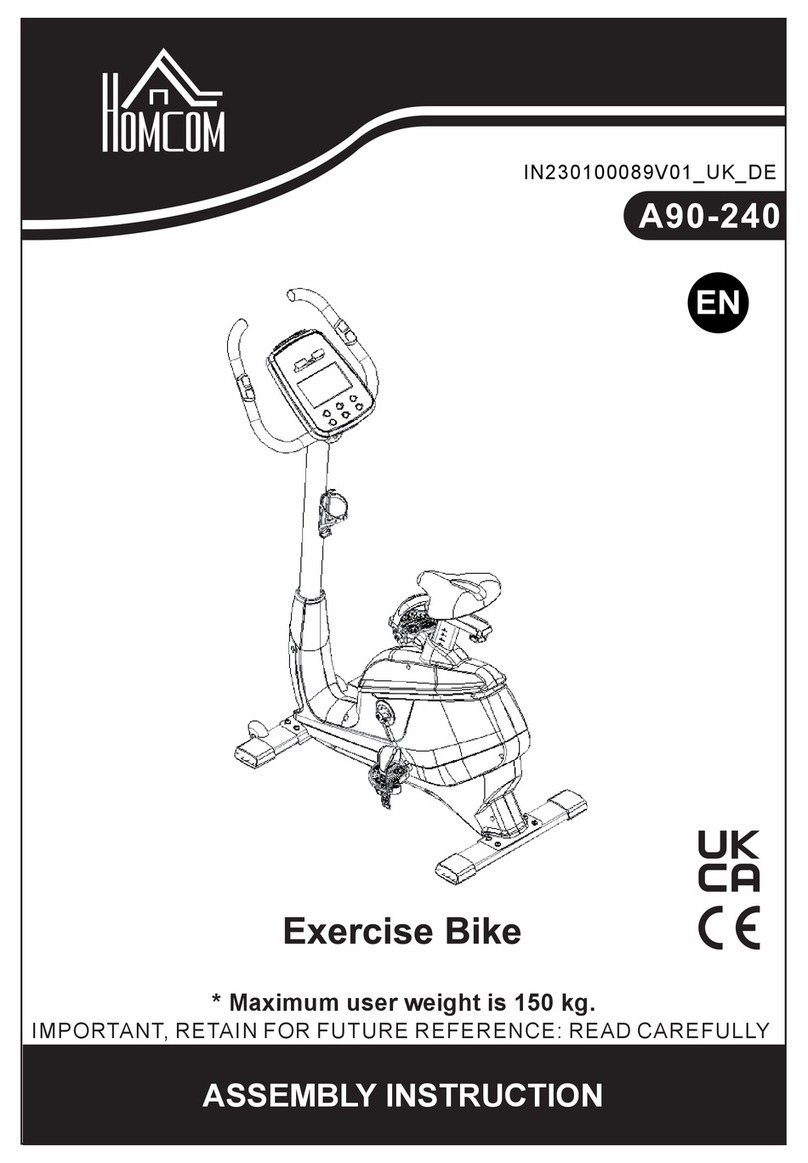
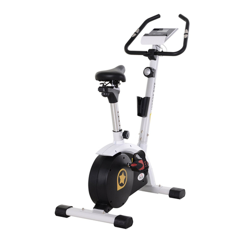
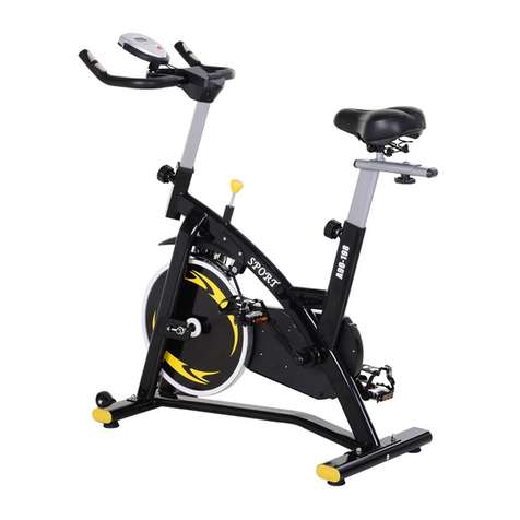
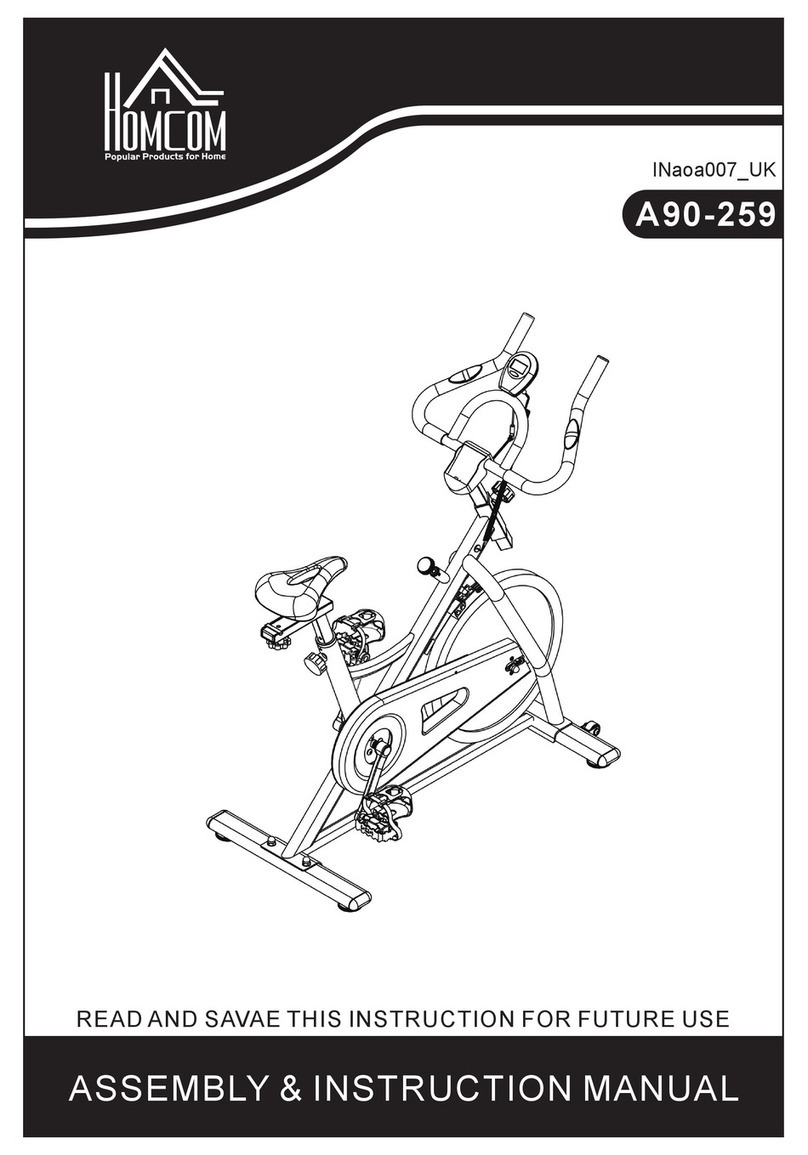
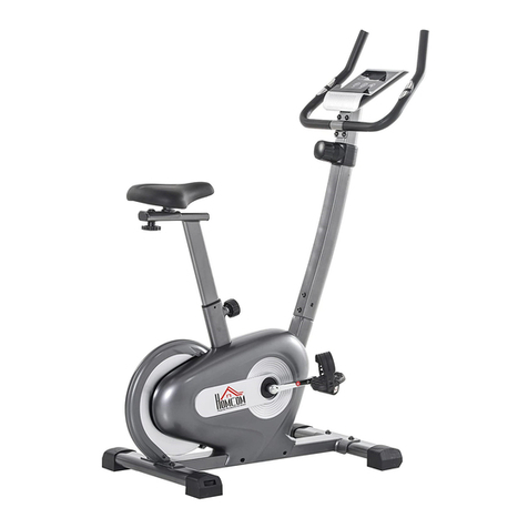
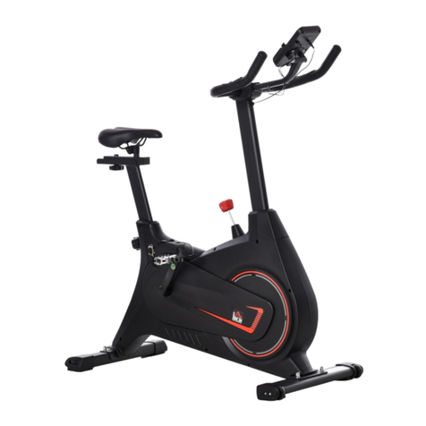
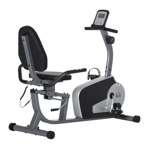
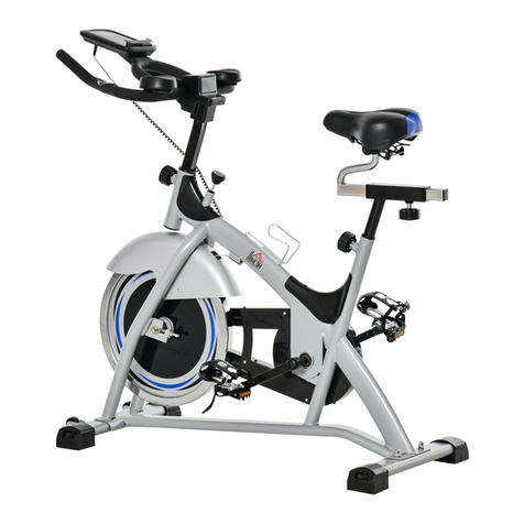
HOMCOM A90-230 User manual

ASSEMBLY INSTRUCTION
INaoc006_UK
A90-230
READ AND SAVE THIS INSTRUCTION FOR FUTURE USE

2
IMPORTANT SAFETY INFORMATION
Please note the following safety precautions before exercising:
1、Read all instructions before assembly & operation;
2、Check all screws, nuts & other connections before using the bike;
3、Do not expose the equipment to damp places, which will cause failure;
4、When assembling, it is best to place parts on a mat (rubber or wood) to avoid
soiling;
5、Before exercise, make sure that no other items are placed within 2 meters around
the equipment;
6、Clean only with a damp cloth, do not use solvent cleaners and also note after each
exercise should be wiped off the sweat on the equipment;
7、Incorrect or excessive exercise can damage your health. It is recommended to
consult a doctor before exercising. They will give you a maximum amount of training
(including pulse, watts, duration, etc.) so that you can Exercise and get accurate
information. Note:This equipment is not suitable for therapeutic use;
8、only when the machine is in normal conditions to exercise, maintenance can only
use the original accessories provide by the factory;
9、This machine can only be used by one person at a time;
10、Always wear sport clothes and sports shoes when exercising, especially the sports
shoes must fit.
11、If at any time during exercise you feel faint, dizzy or experience pain, stop and
consult your physician.
12、Children and disabled persons can only use when they are under guardianship;
13、This bike has the function to let the resistance be adjusted for motion intensity. Make
sure to adjust it to your preference.
14、The maximum weight capacity of this unit is 100 kilograms.
15、This equipment is designed for indoor use only!
Attention: Make sure all screws and nuts are tightened before Exercise
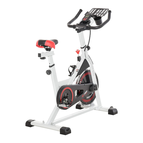
TIP: THE FRONT END CAP CAN BE MOVED, IT ALLOWS YOU TO MOVE THE BIKE.

3
EXPLODED DRAWING AND PARTS LIST
EXPLODED DRADWING AND HARDWARE PACKAGE No.1 :

4
Parts List No.1 :
No. Description QTY No. Description QTY
1 Rear Stabilizer 1 39 Foam Grip 2
2 Rear End Cap 2 40 Screw M8*60 2
3 Screw M10*57 4 41 Screw M8*20 3
4 Front Stabilizer 1 42 Front Post 1
5 Front End Cap 2 43 Bushing 2
6 Washer D10 4 44 Washer φ19 2
7 Nut M10 4 45 Monitor 1
8 Screwφ16×89×1/2"×20-L 1 46 Screw M5*10 2
9 Washer φ16 2 47 Hand Pulse 2
10 Bushing φ28 4 48 Washer φ6*φ12*1 2
11 Washer φ13 2 49 Screw ST4.2*20 2
12 Nylon Nut 1/2"×20- L 1 50 Middle Handle Bar 1
13 Cap S18 2 51 Foam Grip 2
14 Screw φ16×89×1/2"×20-R 1 52 Plug 2
15L Pedal Tube-L 1 53 Middle Wire 1
15R Pedal Tube-R 1 54 Tension Control 1
16 Nylon Nut 1/2"×20-R 1 55 Screw M5*40 1
17 Pedal 2 56 Washer D5 1
18 Screw M10×45 7 57 Plug 2
19 Washer φ10.5*φ20*2 4 58 Crank 1
20 Nylon Nut M10 6 59 Main Frame 1
21 U Shape Seat 2 60 Sensor Wire 1
22 Wash φ10.5*φ26*2 4 61 Wrench S6 1
23 Nylon Nut M8 4 62 Wrench S8 1
24 Cap S13 6 63 Wrench S13-14-15 1
25 Bushing 2 64 Wrench 17-19 2
26 Bushing φ32 4 65 Washer φ8.5*φ16*1.5 5
27 Screw M8×65 2 66 Plastic Cover 1
28L Coupler Bar-L 1 67 Screw ST4.2*20 7
28R Coupler Bar-R 1 68 Wire Plug Φ12 2
29 Screw M8*16 2 69 Screw M8*30 2
30 Washer D8 7 70 Seat Cushion 1
31 Washer φ8.5*φ32*2 2 71 Bushing 1
32 Bushing φ32 4 72 Adjust Tube 1
33 Screw M8*35 2 73 Seat Tube 1
34 Washer D8 9 74 Knob 1
35 Nut M8 2 75 Knob 1
36 Cushion 2 76 Plug 2
37L Handle Bar-L 1 77 Nut M8 3
37R Handle Bar-R 1 78 Washer φ8.5*φ19*1.5 3
38 Cap φ28 2 79 Cushion 1
5
EXPLODED DRADWING AND HARDWARE PACKAGE No.2:
Part List No.2:
90 Bearing 6001RS 2 109 Magnet Grid 1
91 Bearing Seat 2 110 Spring 1
92 Inertial Axle 1 111 Screw ST3*10 5
93 Inertial Wheel 1 112 Nut M6 3
94 Nut 2 113 Screw M6*60 1
95 Washer 1 114 Washer φ10.5*φ20*2 1
96 Nut 1 115 Bushing 1
97 Ball Shelf 2 116 Idler Wheel 1
98 Bowl 2 117 Screw M6*9 6
99 Nut 1 118 Screw M6*30 1
100 Washer 1 119
L Chain Cover-L 1
101 Belt Pulley 1 119
R Chain Cover-R 1
102 Magnetic 1 120 Bearing Plate 2
103 Belt 360PJ6 1 121 Screw ST4.2*16 5
104 Washer D6 2 122 Sensor 1
105 Ring D12 2123 Hole Seal 2
106 Magnet Board Bearing 1124 Nylon Nut M10 1
107 Magnet Board 1125 Screw M6*15 4
108 Magnet 4 126 Washer φ6.5*φ16*1.5 4

6
Assembly Instructions
1.Preparatory work:
A. Make sure there is enough space before installation;
B. Confirm all of the components are all-ready before installation. ( refer to previous product
exploded view which indicates the name and the location of the components);
C. Use the provided tools or the special self-contained tools to install。
2. Assembly instructions:
Step 1:
Screw Front and Rear Stabilizer (4&1) on Main Frame (59) with Screw (3), Washer (6) and Nut (7).

7
Step 2:
Screw Tension Control (54) on Front Post (42) with Washer (56) and Screw (55). Then connect
Middle Wire (53) and Sensor Wire (102); and connect Tension Control (54) and Sensor Wire (60).
Screw Front Post (42) on Main Frame (59) with Screw (40), Screw (41) Washer (30) Washer (34)
and Nylon Nut (23).

8
Step 3:
Screw Coupler Bar(28L&R) on Front Post (42) with Screw (29), Washer (30), Washer (31) and cover
with Cap (24); Screw Pedal Tube(15R) on Crank (58) with Screw (14), Washer (9), Washer (11), Nylon
Nut (16) and Cover with Cap (13). Screw Pedal Tube (15L) on Crank (58) with the same operation.
Attn: The Screw of Pedal separate with L and R mark, Mark “R”should be clockwise, Mark “L”should
be Counter-clockwise.

9
Step5:
Put the Wire Plug (68) out of Front Post (42), then put Hand pulse wire out of the Monitor Seat (42),
then put Wire Plug (68) back to the hole of Front Post (42).
Then screw the Middle Handle bar (50) on Front Post (42) with Screw (69), Washer (30), Washer (65).
Then connect Monitor (45) and Middle Wire (53), Hand Pulse (47), then screw Monitor (45) on Front
Post (42) with Screw (46) and cover with Cap (66).
Step 4:
Screw Pedal (17) on Pedal Tube (15L&R) with Screw (18), Washer (19), Nylon Nut (20).

10
Step 6:
Screw Handle Bar(37L) into Coupler Bar(28L), align the holes and screw it with Screw(33),
Washer(34) and Nut(35); Screw the Right Handle Bar(37R) as above operation.
Step 7:
Pass the Adjust Tube (72) through Seat Tube (73).Knob (74) through Washer(65),Seat Tube(73) and
screw it with Adjust Tube(72).

11
Step 8:
Screw Seat Tube (73) into Main Frame(59),Screw Knob(75) into Main Frame(59),the head of the
knob(75) should be aligned with the Hole of Seat Tube(73).

12
EXERCISE INSTRUCTIONS
The Warm Up Phase
This stage helps get the blood flowing around the body and the muscles working properly. It will
also reduce the risk of cramp and muscle injury. It is advisable to do a few stretching exercises as shown
below. Each stretch should be held for approximately 30 seconds, do not force or jerk your muscles into
a stretch - if it hurts, STOP.
1 2
3
4
5
1.Down Stretch
Bend your knees slightly and body slowly, let your
back and shoulders relax, and try to touch your toes.
Keep it for 10 ~15 seconds, repeat 3 times.
2. Hamstring Stretch
Sitting on a clean cushion, then bend your right foot.
Place your left foot against the inner thigh of your
right foot. Try to touch your toes 。Keep it for 10
~15 seconds, repeat each foot 3 times.
3. Calf and Foot Stretching
Stand and place both hands on a wall or a tree, one
foot behind. Keep the behind foot stand and it’s heel
on the floor, then tilt to the wall or tree. Keep it for 10
~15 seconds, repeat each foot 3 times.
4 Quadriceps Stretch
Place your left hands against a wall or a desk to aid
your balance. Then grasp your ankle with your left
hand and pull your foot toward your buttocks. Keep it
for 10 ~15 seconds, repeat each foot 3 times.
5. Groin Stretch
Sit with your knees flexed and soles of feet together.
Hold your ankles and bend at your hips. Keep it for
10 ~15 seconds, repeat 3 times.

13
Exercise Stage
This stage should last for a minimum of 12 minutes though most people start at about 15~20 minutes.
After times, you can increase training strength. After exercising for a period of time, your heart rate will
be close to the “target zone”(shaded part) in the graph as shown below. Note: Getting in a better
shape will not happen overnight and will require working out consistently.
Recovery Phase
This stage is to let your Cardiovascular System and muscles wind down. This is a repeat of the warm up
exercise e.g. reduce your tempo, continue for approximately 5 minutes. Then repeat the exercise phase,
please be careful not to force or jerk your muscles.
When using elliptical fitness exercises, please don't increase training intensity arbitrarily. It may sprain
your leg muscles, which means you can't continue exercising for a long time.
Equipment Tip
Adjusting the Tension Control can change the resistance of the equipment, the higher resistance the
harder it is to step. Users can use this to find a suitable speed.

Table of contents
Other HOMCOM Exercise Bike manuals

HOMCOM
HOMCOM A90-301 User manual

HOMCOM
HOMCOM A90-196 Installation guide

HOMCOM
HOMCOM A90-254 Installation guide

HOMCOM
HOMCOM A90-198 User manual

HOMCOM
HOMCOM A90-200 User manual

HOMCOM
HOMCOM A90-259 Installation guide

HOMCOM
HOMCOM A90-301 User manual

HOMCOM
HOMCOM A90-237 User manual

HOMCOM
HOMCOM A90-194 User manual

HOMCOM
HOMCOM A90-301 User manual
Popular Exercise Bike manuals by other brands

Matrix
Matrix A7XI-01 Service manual

Body Champ
Body Champ BF 620 owner's manual

Finnlo
Finnlo CORUM STRESSLESS manual

U.N.O
U.N.O MOTIVE FITNESS V-fit AB MAGNETIC X-BIKE H.P. Assembly & user manual

Stages cycling
Stages cycling STaGESSOLO LES MILLS VIRTUAL BIKE SC4.21 Assembly guide

Club
Club PRO HM6004M user manual