manuals.online logo
Brands
  1. Home
  2. •
  3. Brands
  4. •
  5. HOMCOM
  6. •
  7. Motorized Toy Car
  8. •
  9. HOMCOM 370-149V70 User manual

HOMCOM 370-149V70 User manual

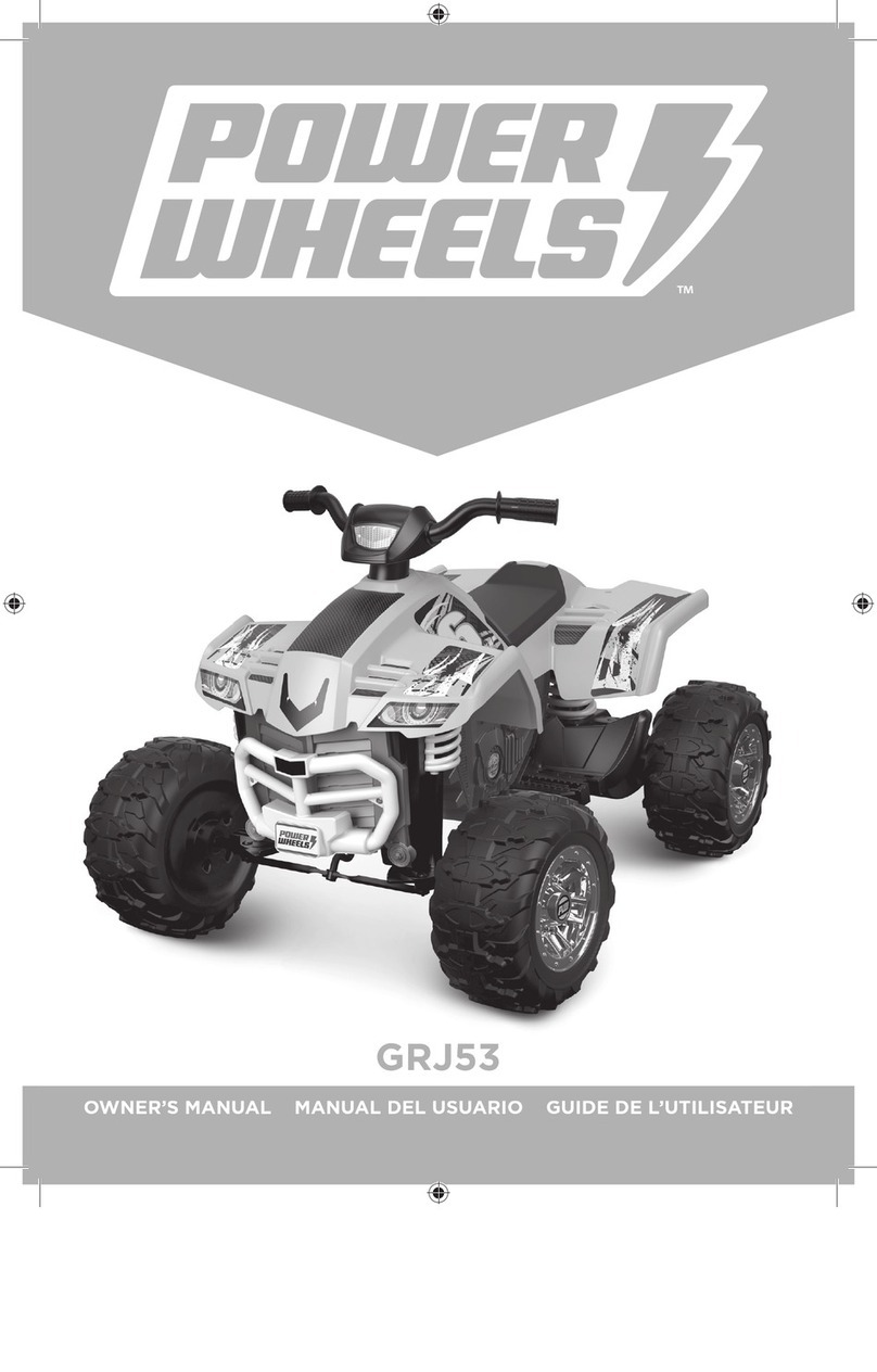
ASSEMBLY INSTRUCTION
INfda005V01_UK
370-149V70
READ AND SAVE THIS INSTRUCTION FOR FUTURE USE
FOR THE SAFETY OF YOUR CHILD, PLEASE READ ALL WARNINGS AND
ASSEMBLY/USE INSTRUCTIONS. KEEP THIS GUIDE FOR FUTURE
REFERENCE.
●ADULT ASSEMBLY REQUIRED. The product contains small parts, which
are for adult assembly only. keep small children away when assembling.
●always remove protective material and poly bags and dispose before
assembly.
●never leave child unattended. direct adult supervision is required.
●always keep child in view when child is in vehicle.
●Keep Children within Safe Riding Areas:
- Never use in roadways, near motor vehicles, on lawn space, on or near
steep inclines or steps, swimming pools or or any other dangerous area.
●Use the toy only on flat surfaces. Such as inside your house, garden or
playground.
●Never use in the dark. A child could encounter unexpected obstacles and
have an accident. Operate the vehicle only in the daytime or a well-lit area.
●Please avoid running on sand or any other rough ground.
●always wear shoes.
●always sit on the seat.
●this toy has no brake.
●It is prohibited to change the circuit or add other electric parts
●Inspect wires and connections of the vehicle periodically.
●Do not let any child touch the wheels or be near them when the car is
moving.
●This vehicle has adjustable play seat belts. Please instruct children how to
tie the safety belt before using, guarantee the security.
SPECIFICATIONS:
Battery:
Motor:
Suitable ages:
Maximum weight:
Speed :
Power way:
Use of time:
Charger:
Charging type
Charg: 8-12 hours ; Use: 1-2 hours
Input AC
110 V~240, output DC12V
1000mA
WARNING
1.The pictures in this instruction is only for explaining the operation and
structure of the product, when there's any difference with the real
product, please confirm with the real product.
2.In order to improve the quality of the product, we may amend some
structure or appearance of the product without notification. Thank you for
your understanding.
12V10AH *1
37-96 months
30KG
3-6KM/h
2*555(120W)
User Notice │ 1
STORAGE BATTERY INFORMATION AND MAINTENANCE
●Please charge 8 to 12 hours before first time use.
●Please use the suitable adapter to charge storage battery, otherwise the
ride-on will be damaged.
●Please charge the car once the speed is slower than normal, otherwise it
will decrease storage battery life.
●Please fully charge the battery before you put your ride-on away, and
remember to recharge the battery every 30 days. This will ensure the normal
use of the battery, otherwise, the battery might not hold a charge without
proper maintenance.
● Batteries may leak fluids that can cause chemical burn injury or ruin your
product.
● To avoid battery leakage: Do not mix old and new batteries or batteries of
different types: alkaline, standard (carbon-zinc) or rechargeable (nickel-
cadmium).
● Insert batteries as indicated inside the battery compartment. Remove
batteries during long periods of non-use.
●Always remove exhausted batteries from the product. Dispose of batteries
safely. Do not dispose of batteries in a fire. The batteries may explode or
leak.
● Never short-circuit the battery terminals.
● Non-rechargeable batteries are not to be recharged.
● Use only batteries of the same or equivalent type as recommended.
● Do not charge non-rechargeable batteries.
● Remove rechargeable batteries from the product before charging.
● If removable rechargeable batteries are used, they are only to be charged
under adult supervision
● Every single charging can not go over 20 hours. Both charger and storage
batteries will occur mildly warm during charging. Do not use mal-functioned
adapter or storage battery unless they are repaired.
●Charger and storage batteries are not considered as toys.
●Please make periodical inspection for storage battery, especially for
adapter wires and plugs.
●Please turn off the switch when the ride-on is not in use. Please do a full
charge after long periods of inactivity.
●Charge in well ventilated, dry place. Do not open the battery or the charger.
● Tighten the screws with a screwdriver. DO NOT over tighten
Disposal Of Battery:
1.Your sealed lead-acid battery must be recycled or disposed of in an
environmentally sound manner.
2.Do not dispose of your lead-acid battery in a fire. The battery may explode
or leak.
3.Do not dispose of a lead-acid battery in your regular, household trash. The
incineration, land filling or mixing of sealed lead-acid batteries with house-
hold trash is prohibited by law.
PREVENT FIRE AND ELECTRIC SHOCK:
- Use the only rechargeable battery and charger supplied with your vehicle.
-NEVER substitute the battery or the charger with another brand. Using
another battery or charger may cause a fire or explosion.
-Do not use the battery or charger for any other product. Overheating, fire or
explosion could occur.
- NEVER modify the electric circuit system. Tampering with the electric
system may cause a shock, fire or explosion or may permanently damage the
system.
-Do not allow direct contact between battery terminals. Fire or explosion can
occur.
-Do not allow any type of liquid on the battery or its components.
-Explosive gasses are created during charging. Do not charge near heat or
flammable materials. Charge the battery in a well- ventilated area ONLY.
- NEVER pick up the battery by the wires or charger. Damage can occur to
the battery and may cause a fire. Pick up the battery by the case ONLY.
Charge the battery in a dry area ONLY.
●Battery posts, terminals and related accessories contain lead and lead
compounds, chemicals known to the State of California to cause cancer and
reproductive harm. Wash hands after handling.
●Do not open the battery. Battery contains lead acid and other materials that
are toxic and corrosive.
●Do not open the charger. Exposed wiring and circuitry inside case may
cause electric shock.
ONLY adults may handle or charge the battery. NEVER allow child to handle
or charge the battery. Battery is heavy and contains lead acid (electrolyte).
●Do not drop the battery. Permanent damage to the battery could occur or
cause serious injury.
●Before charging the battery, check for wear or damage to the battery,
charger, its supply cord and the connectors. DO NOT charge the battery if
any damage to parts has occurred.
Do not allow the battery to drain completely. Recharge the battery after each
use or once a month if not used regularly.
●Do not charge battery upside down.
●Always secure the battery with the bracket. Battery can fall out and injure a
child if vehicle tips over.
●It is parents' responsibility to check main parts of the toy before using, Must
regularly examine for potential hazard, such as the battery, charge, cable or
cord, plug, screws are fastening enclosure of other parts and that in the
event of such damage, the toy must not be until that damage had been
properly removed. Make sure the plastic parts of the vehicle are not cracked
or broken.
●Occasionally use a lightweight oil to lubricate moving parts such as wheels.
●Park the vehicle indoors or cover it with a tarp to protect it from wet weather.
●Keep the vehicle away from sources of heat, such as stoves and heaters.
Plastic parts may melt.

●Recharge the battery after each use. Only an adult can handle the battery.
Recharge the battery at least once a month when the vehicle Raider is not
being used.
●Do not wash the vehicle with a hose. Do not wash the vehicle with soap and
water. Do not drive the vehicle in rainy or snowy weather. Water will damage
the motor, electric system and battery.
●Clean the vehicle with a soft, dry cloth. To restore shine to plastic parts, use
a non-wax furniture polish. Do not use car wax. Do not use abrasive
cleaners.
●Do not drive the vehicle in loose dirt, sand or fine gravel which could
damage moving parts, motors or the electric system.
●When not using, all the electrical source should be turn off. Turn off the
power switch and disconnect the battery connection.
HINT: Some parts shown are assembled on both sides of vehicle
Parts Diagram │ 2
Roof
PART
NO.
REMARKS
PART NAME
Q’ty (pcs)
Vehicle body
Rear wheel
Front wheel
Ø12 washer
Lock nut
Split pin
Hubcap
Steering column
Steering wheel
M5x35 machine screw
Ø5 nut
Front bumper
Ø4x12 flat head screw
Bakset base
Bakset fence
Shift lever assembly
Protecting board
Seat
Seat back
M5x16 machine screw
Rear axle
Spanner
Charger
Ø4x12 round head screw
M5x25 machine screw
Taillight cover
Rear bed board
Remote controller
Roof
Roof beam
Roof front support
Roof rear support
For R/C type only
Left and right
Left and right
Left and right
Left and right
Left and right
Parts List │ 3
1
2
3
4
5
6
7
8
9
10
11
12
13
14
15
16
17
18
19
20
21
22
23
24
25
26
27
31
32
33
34
35
1
2
2
8
4
5
4
1
1
1
9
2
28
1
1
1
1
1
1
2
1
2
1
4
8
2
1
1
1
2
2
2
Placed on the steering wheel
1
2
Attach the Front Bumpers & Tailight Cover │ 4
Assembly tools required (not included):
Screwdriver
Long nose pliers
1. Insert the tabs on the front bumper into the
holes on the front of the vehicle, push until
you hear it “click” into place.
2. Insert the left and right taillight covers
and “snap” into place.
1
2
Turn the vehicle body downside up.
1. Insert the straight end of the steering column through the hole on the steering gear
box, the hole on the vehicle body, and out through hole on the dash. Ensure the gear
part on the steering column matchs up with the steering gear box.
2. Slide a Ø12 washer onto the steering column from the bent end.
Type /RC - Attach the Steering Column │
5
HINT: The follow steps only for the type R/C.
Front Bottom View
1
1
2
3
4
8-1
8-2
8-3
Reset the Front axle │
6
Ø6 lock nut
Ø6 washer
Ø12 washer
Steering column
M6X20 machine
screw
Front axle
linkage
Split pin
Front axle
plate
Front axle
plate
Front Bottom View
Cut off the plastic tie on the front axle with scissors.
1,2. Adjust the front axle plate so that the axle is in the correct position as shown
(8-1);
3. Slide a Ø12 washer onto the steering column from the bent end.
4. Insert the split pin into the hole on the bent end of the steering column. Bend the
ends of split pin back using a long nose pliers (not included).
5. Remove the M6x20 machine screw, Ø6 washer and Ø6 lock nut from the front axle
linkage. Reinsert the M6x20 machine screw through the hole on the front axle
linkage, the Ø6 washer, the hole on the front axle plate, and fasten the Ø6 lock nut
to the opposite end of the screw.
1
2
3
4
6
5
Rear Bottom View
2. Slide the rear wheel onto the rear axle .
3. Slide the Ø12 washer onto the rear axle.
4. Tighten a lock nut to the end of the rear axle with a spanner.
Repeat the 2-4 steps for the other rear wheel.
HINT: An extra spanner has been provided to hold the Lock Nut on the other side of the rear
axle while tightening the Lock Nut on the other side. DO NOT over tighten.
5. Insert a split pin into the hole on the each end of the rear axle. Bend the ends of split pins
back using a long nose pliers (not included).
6. “Snap” a hubcap to each rear wheel.
Cut off the plastic ties on the gear boxes. Remove all the parts
from the rear axle.
1. Insert the rear axle through the hole in the vehicl body, when inserting it half way,
lift the another gear box so that the rear axle can go through it and protrude out.
Make sure that the rear axle is centered with left and right ends exposed the same
distance outside of the ride-on toy body.
Attach the Rear Wheels │
7
Hole on the gear box
43
2
1
6
Attach the Front Wheels │
8
Front Bottom View
Remove all the parts from the front axle.
1. Slide a Ø12 washer onto the front axle.
2. Slide a front wheel onto the front alxe.
3. Slide a Ø12 washer onto the front axle.
4. Tighten a lock nut to the end of the front axle with a spanner. DO NOT over tgithen.
5. Insert the split pin into the hole on the end of the rear axle. Bend the ends of split
pin back using a long nose pliers (not included).
6. “Snap” the hubcap to the wheel.
Repeat the above procedure to assemble the other front wheel.
GAP
After assembling any wheel to the axles, please check the gap
between the screw thread and the collapsible (refer to below
picture), if the gap is too big, please add two or three washers
inside the wheel, but after tightening the nut outside the wheel,
please turn the wheel by your finger to check if the wheel can
run smoothly, this is very important, because if the wheel can
run smoothly, it is ok, but if the nut press the wheel and the
wheel can’t run smoothly, the motor will be broken easily! Then
you need to decrease one or two washers to make sure the
wheel can run smoothly!
5
2
4
31
6
7
5
Remove the M5x35 machine screw and Ø5 nut from the steering wheel.
Turn the vehicle body upright.
5. Place the steering wheel over the the steering column, protruding from the middle of
1. With a screwdriver remove the
screw on the battery cover located
in the center of the steering wheel.
2. Remove the battery cover from the
top of the battery compartment.
3. Insert 2x1.5 AA batteries in their
correct polarities.
4. Place the battery cover over the
battery compartment and fasten
with the screw you removed in step
one.
Attach the Steering Wheel
Attach the Steering Wheel │
9
HINT: If the steering wheel of your vehicle equipped with the sound function, please
follow the steps 1-4 to add the batteries (Not Included), and refer to the battery
information on page 2.
the steering wheel base.
6. Align the holes on each side of steering
End of steering column
wheel with the holes at the end
of the steering column.
7. Fasten a nut on the opposite
end of the screw to secure the
steering wheel to the steering
column.
1
2
3
4
5
Attach the Shift Level Assembly & Protecting Board │ 10
1. Lift up the shift lever assembly and remove the four Ø4x12 round head screws
with a screwdriver.
2. Push the Shift Lever Assembly forward and locate it over the 4 screws mounting
brackets as shown.
3. Secure it by tightening the four removed screws.
4. Fit the protecting board to the vehicle body.
5. Tighten securely with two Ø4x12 flat head screws with a screwdriver.
1
2
Connect the Power Supply & Attach the Rear Bed Board │ 11
1. Plug the battery connector into the vechiel connector, push firmly.
2. Fit the tabs on the rear bed board into the slots located in the rear vehicle body, and
press down until it “clicks” into place.
1
3
4
2
5
8
6
9
7
Attach the Seat & Attach the Basket │ 12
1. Fit the seat back to the seat.
2. Insert two Ø4x12 flat head screws from the the bottom side of the seat, through the seat and
into the seat back, and tighten.
3. Fit the seat assembly to the vehicle body.
4. Insert four Ø4x12 flat head screws on the seat back and tighten.
5. Insert two M5x16 machine screws through the seat and into the vehicle body, and tighten with
a screwdriver.
6-7. Fit the basket fence to the basket base, insert four Ø4x12 flat head screws and tighten.
8-9. Fit the cargo basket to the bonnet. Insert four Ø4x12 flat head screws and tighten.
2
1
2
1
3
5
7
4
6
L1
L1
L2
L2
1. Using a screwdriver to remove the M5x25 machine screws and Ø5 nuts from the left and right
roof beams.
2. Fit the both roof beams to the roof.
3. Insert three Ø4x12 flat head screws and tighten on each beam.
4-5. Fit the rear rollbar support to the roof beam, secure with M5x35 machines *2 and Ø5 nut *2
you removed in step one. Repeat for the other side. (L2 to L2, R2 to R2)
6-7. Fit the front rollbar support to the beam, secure with M5x35 machines *2 and Ø5 nut *2 you
removed in step one. Repeat for the other side. (L1 to L1, R1 to R1)
“R” marked
“R” marked
“L” marked
“L” marked
HINT: The roof, roof beams, roof front supports and roof
rear supports are marked “L” and “R”, aslo they are
Attach the Roof(1) │ 13
HINT: The follow steps only for the type with roof.
designed to assemble together in only one way. Please
follow the guides: L to L (L1 to L1, L2 to L2), R to R (R1 to R1, R2 to R2)
1
23
1. Fit the roof assembly to the vehicle body.
2. Insert a Ø4x12 flat head screw through the roof front support and into the bonnet,
and tighten with a screwdriver. repeat for the other side.
Attach the Roof(2) │ 14
HINT: The follow steps only for the type with roof.
3. Insert two Ø4x12 flat head screws through
the rear rollbar support and into the vehicle
body. and tighten with a screwdriver. repeat
for the other side.
Type with roof completed.
1
3
2
4
5
Use Your Ride-on │ 15
Use the vehicle on generally level ground ONLY!
DO NOT Use the vehicle on Lawn space!
●Always stop vehicle when changing the speed (if equipped) or direction to
avoid damage the gears and motor.
IMPORTANT
1. Power button: Turns the vehicle on and off.
2. Low speed forward/reverse shifter: Changes the direction that vehicle moves from forward
to reverse.
●To move the vehicle forward, shift the lever to top position.
●To move the vehicle backward, shift the lever to down position.
3. Foot pedal: Applies power (speed) to the vehicle.
●To move the car, press the pedal down.
●To brake or slow down, release pressure from the pedal.
4. Sound buttons: Press for sound playing.
5. 3.5mm AUX input: Allow the audio from your portable music player or phone to be played
through the vehicle speakers. MP3 format ONLY.
B
A
Using the High Speed │
16
●The High Speed Protective cover must be removed by an adult.
●Before remove the HIGH SPEED protective cover: Make sure your child knows
how to steer, how to start and stop the product and knows the rules for safe
driving.
IMPORTANT
ReverseReverse
Low speed
forward
Low speed
forward
High speed forwardHigh speed forward
A. Remove the two screws on the top of the high speed protective cover with a
screwdriver.
B. Remove the high speed protective cover.
Then you can push the shifter into the “high speed” position.
C. Press down the foot pedal.
HINT: The product is designed to operate in low speed only in reverse.

Other HOMCOM Motorized Toy Car manuals

HOMCOM LAMBORGHINI AVENTADOR SVJ User manual

HOMCOM

HOMCOM LAMBORGHINI AVENTADOR SVJ User manual

HOMCOM 370-217V70 User manual

HOMCOM

HOMCOM 370-217V70 User manual

HOMCOM 301-058 User manual

HOMCOM

HOMCOM 301-058 User manual

HOMCOM 370-159V90 User manual

HOMCOM

HOMCOM 370-159V90 User manual

HOMCOM 370-240V90 User manual

HOMCOM

HOMCOM 370-240V90 User manual

HOMCOM Mercedes-AMO GT R User manual

HOMCOM

HOMCOM Mercedes-AMO GT R User manual

HOMCOM 370-096 User manual

HOMCOM

HOMCOM 370-096 User manual

HOMCOM 370-238V90 User manual

HOMCOM

HOMCOM 370-238V90 User manual

HOMCOM 370-300V90 User manual

HOMCOM

HOMCOM 370-300V90 User manual

HOMCOM 370-187V90 User manual

HOMCOM

HOMCOM 370-187V90 User manual

HOMCOM 370-227V70 User manual

HOMCOM

HOMCOM 370-227V70 User manual

HOMCOM 370-245V00 User manual

HOMCOM

HOMCOM 370-245V00 User manual

HOMCOM 370-289V90 User manual

HOMCOM

HOMCOM 370-289V90 User manual

HOMCOM Children ATV User manual

HOMCOM

HOMCOM Children ATV User manual

HOMCOM Mercedes.Benz ElC400 4,A1IC User manual

HOMCOM

HOMCOM Mercedes.Benz ElC400 4,A1IC User manual

HOMCOM 370-159V70 User manual

HOMCOM

HOMCOM 370-159V70 User manual

HOMCOM 370-187V70 User manual

HOMCOM

HOMCOM 370-187V70 User manual

HOMCOM Lambo V12 Vision Gran Turismo User manual

HOMCOM

HOMCOM Lambo V12 Vision Gran Turismo User manual

HOMCOM BENTLEY MULSANNE User manual

HOMCOM

HOMCOM BENTLEY MULSANNE User manual

HOMCOM 370-097 User manual

HOMCOM

HOMCOM 370-097 User manual

HOMCOM 370-188V70 User manual

HOMCOM

HOMCOM 370-188V70 User manual

HOMCOM 370-235V70 User manual

HOMCOM

HOMCOM 370-235V70 User manual

HOMCOM 370-169V70 User manual

HOMCOM

HOMCOM 370-169V70 User manual

HOMCOM Lambo V12 Vision Gran Turismo User manual

HOMCOM

HOMCOM Lambo V12 Vision Gran Turismo User manual

Popular Motorized Toy Car manuals by other brands

Kyosho MR-02 user guide

Kyosho

Kyosho MR-02 user guide

Hobbytech BXR.S2 RTR instruction manual

Hobbytech

Hobbytech BXR.S2 RTR instruction manual

Serpent 750 EVO Insruction manual

Serpent

Serpent 750 EVO Insruction manual

Traxxas Revo 3.3 53097 owner's manual

Traxxas

Traxxas Revo 3.3 53097 owner's manual

ahead RC Crawler Cat 1 Assembly manual

ahead RC

ahead RC Crawler Cat 1 Assembly manual

Reely Dart 2.0 operating instructions

Reely

Reely Dart 2.0 operating instructions

PR RACING PR S1 V3 TYPE R(FM) EVO manual

PR RACING

PR RACING PR S1 V3 TYPE R(FM) EVO manual

Fisher-Price Power Wheels C2390 Owner's manual with assembly instructions

Fisher-Price

Fisher-Price Power Wheels C2390 Owner's manual with assembly instructions

Mugen Seiki Nitro MTX-2 instruction manual

Mugen Seiki

Mugen Seiki Nitro MTX-2 instruction manual

Traxxas 7014 quick start guide

Traxxas

Traxxas 7014 quick start guide

Jamara Mercedes Benz SL65 AMG instructions

Jamara

Jamara Mercedes Benz SL65 AMG instructions

Serpent S120 PRO instruction manual

Serpent

Serpent S120 PRO instruction manual

Team Losi XXT CR owner's manual

Team Losi

Team Losi XXT CR owner's manual

THUNDER TIGER EB-4 G3 6400-F instruction manual

THUNDER TIGER

THUNDER TIGER EB-4 G3 6400-F instruction manual

Kidzone 060-ROT-23L instruction manual

Kidzone

Kidzone 060-ROT-23L instruction manual

Parrot JETT user guide

Parrot

Parrot JETT user guide

HOLLICY SX2018 Assembly manual

HOLLICY

HOLLICY SX2018 Assembly manual

Blackzon Slayer instruction manual

Blackzon

Blackzon Slayer instruction manual

manuals.online logo
manuals.online logoBrands
  • About & Mission
  • Contact us
  • Privacy Policy
  • Terms and Conditions

Copyright 2025 Manuals.Online. All Rights Reserved.