manuals.online logo
Brands
  1. Home
  2. •
  3. Brands
  4. •
  5. Honeywell
  6. •
  7. Burner
  8. •
  9. Honeywell PRO 2000 Series User manual

Honeywell PRO 2000 Series User manual

INSTRUCTIONSHEET
Q334 AND Q385 “2000”series
PILOTBURNERS
EN1R--9095 0002R5--NE
Q334A
Q385A
APPLICATION
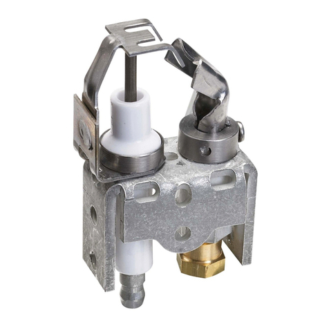
Q334Aand Q385Anon primaryaerated target type pilot
burnersprovide main burnerignition forgasappliancesusing
manufactured,naturalorLPgas.
Q334Aand Q385 pilotburnersare used inconjunction with a
Honeywell thermocouplewhich hasto provethe presence of
pilot flame beforemain gasisadmitted intothe appliance.
SPECIFICATIONS
Models
Q334A:non primaryaerated largetarget type pilotburner.
Q385A:non primaryaerated small target type pilotburner.
Q334Apilotburnersare availablewiththree mounting
brackets.and withtargetposition K(righthanded)orL(left
handed).See fig.4.
Q385Apilotburnersare availablewiththree mounting
brackets.and withtargetposition K(righthanded),F(straight)
orL(left handed).See fig.5.
Q385Apilotburnersare provided withaclipforeasy
mounting ofan ignition electrode.
Dimensions
Q334A:see fig.4.
Q385A:see fig.5.
Consumption
Q334A:approximately250 Watt
Q385A:approximately100 Watt
Maximumoperating temperatures
At target tip:
Q334A:815 _C
Q385A:730 _C
Atorifice assy:340 _C
Recommendedthermocouple
Q334Apilotburnerisdesigned forusewithQ309Aand
Q335Cthermocouple.
Q385Apilotburnerisdesigned forusewithQ309A
thermocouple
Recommended pressure adjustment
Typeofgas Pressure adjustment
Manufactured (I1)
Natural(I2H)
Natural(I2L)
LP(I3)
Max.
Max.
Max.
Max.
Accessories
To be ordered seperately,see ProductHandbook
EN2R--9002
INSTALLATION
IMPORTANT
Installer mustbeatrained,experienced serviceman.
Turn off gas supplybeforestarting installation.
Animportantrequirement forthe Q334Aand Q385A
pilotburneristhatitmustbe installed carefully.
ConsultHoneywell application engineerswhen
considering using these devices.
Locating pilotburner
·Position foreasy access and observation.
·Position sothatpilot flamewill not touch adjacentpartsor
main burnerflames.
·Position sothatpilot flamewill ignitemain burnerwhen
pilotgaspressurejustexceeds safety shut--off pressure.
·Ensurethatpilot flame hasan amplesupplyofdust free
air.
·Do notexposeto draughtswhichwill extinguish pilot flame.
·Pilotburnershould notextinguishwhen main burneris
switched ONand OFF.
·Pilotburnershall be mounted inapreferablyupright
position.
Mounting pilotburner
Fixpilotburnertomain burneratselected location.Mounting
surfacesotherthan main burnershould be avoided asmuch
aspossiblesincetheymay shift, bend ordeform due toclose
proximityofmain burner.
S
u
b
j
e
c
t
t
o
c
h
a
n
g
e
w
i
t
h
o
u
t
n
o
t
i
c
e
.
P
r
i
n
t
e
d
i
n
t
h
e
N
e
t
h
e
r
l
a
n
d
s
.
EN1R--9095 0002R5--NE2
Mounting ofignition electrode(see fig.1.)
·Placetip ofignition electrode between clip and bracket.
·Pushignition electrode upwards.
·Position electrode tipinthe holeonthe top of the bracket.
·Pushignition electrode furtherupwardsuntil the thickning
passesthe hookof the bracket.
Remounting ofignition electrode(see fig.1.)
·Pushmetalclipsidewards.
·Pull ignition electrode to disengage.
Fig.1.Mounting ofignition electrode
Pilotgas connection (see fig.2.)
·Square off end of tubing,clean,remove burrsand form it.
·With orifice assemblyand compression fitting in position,
insert tubing intotargetspud until itbottomsand turn
compression fitting fingertight.
·Holdtubing to prevent turning and tighten compression
fitting withawrench about twoturnsbeyond fingertight for
6mm tubing and about3/4turn beyond fingertight for4
mm tubing tomakeapressuretightjoint.
CAUTION
Do notbend tubing nearfitting aftertightening asthis
mayresultin gasleakage atconnection.
·Connectotherend of tubing to pilotgas supplyorgas
controlaccording the manufacturer’sinstructions.
Fig.2.Pilotgas connection
Mounting of thermocouple(see fig.5)
Insert thermocoupletipintothermocouplespud ofpilotburner
and tighten withthe attached nut.
Fig.3.Mounting of thermocouple
EN1R--9095 0002R5--NE
3
L
8,5
17,7
9,1
10,1
16
37,5
53,2
19
11,5
63,7
M5(2)
8
41,3
12,5
1,1
22,2
M5(2)
16,5
5
16
37,8
18,1
47,5
63,7
19
16 8,5
33,2
18,1
35,3
9,5
M6
1,1
3,8
8,5
16
19
13
90
K
L
K
LK
20_
20_20_
20
_
20
_
20_
Fig.4.Dimensions and targetposition Q334
ADJUSTMENTAND CHECKOUT
IMPORTANT
Adjustments shouldbemade byqualified personel
only.
If the appliancemanufacturersupplies checkout
and/orservice and maintenanceinstructions,
carefullyfollowthem.
Lightpilot flame
·Beforelighting pilot flame, turnthermostat tothe lowest
setting.
·Shutoff gas supplytothe main and pilotburner.
CAUTION
Wait5minutesto allowcompleteventing ofany
unburned gas.
RememberLPgasisheavierthan airand will notvent
upwards.
·Turn on gas supplyand lightpilot flame according tothe
appliancemanufacturer’sinstruction.
·Pilot flameshould burnwithasteadyblue flame.
Test forgas leakage
Paintall jointswitharichsoap and watersolution.Takecare
not to use an agressivesoap.Bubblesindicateleak.Tostop
leak, tighten jointor make a newone and check again.
Neveruseaflametocheck forgasleakage.
Checkoutmain burnerignition
WARNING
Thistestshould be performed onlyafter main burner
gasinputadjustmentshave been made.
Pilotburnershouldignitemain burnerquietlyand reliable
underall operating conditions,including lowgas supply
pressure.
Pilot flamemustnotsmotherorsnuff outwhen tested as
follows:
·main burnerignition fromcold--start--repeat.
·continuousoperation ofmain burner.
·main burnerignition with appliance atmaximumoperating
temperature afterprolonged operation.
Checkout
Beforeleaving,setappliancein operation and observe
through a completecycleto ensurethatburnersystem
componentsfunction correctly.
EN1R--9095 0002R5--NE4
TROUBLESHOOTING
Pilotoutage
If pilot flame extinguishesduring normaloperation,recheck
Mounting and Location.
It maybe necessarytoconstructashieldto protectpilot flame
againstdraughtsand main burnerignition extinction.
Powerunitdrop out
If powerunitofgas controlfailsto holdin,check the following:
·Pilot flameis correct.
·Powerunitconnection is clean and tight.
·If above doesnotcurethe condition,replace
thermocouple.
19
811,5
12,5
44,5
62 51,5
51,5
16
37,5
21,5
5,7
6,7
8,5
13
2,4
14,6
19
62
16
26,5
16,5
5
47,5
8,5
16
9,5
19
0,5
33,2
41
51,538,5
8,5
14,7
16
2,4
M6
M5(2)
M5(2)
90
K
L
K
L
L
K
3,5
F
10_
10_
10_
10_
10_
10_
Fig.5.Dimensions and targetposition Q385
CombustionControlsCenter Europe
Honeywell BV
PhileasFoggstraat7,Emmen
P.O.Box 83
7800 ABEmmen
NL--TheNetherlands
Tel: +31 (0)591 6959 11
Fax:+31 (0)591 6952 00

Other manuals for PRO 2000 Series

14

This manual suits for next models

4

Other Honeywell Burner manuals

Honeywell Maxon OT FHR User manual

Honeywell

Honeywell Maxon OT FHR User manual

Honeywell SmartValve Q3450A Operation manual

Honeywell

Honeywell SmartValve Q3450A Operation manual

Honeywell Eclipse WX0050 User manual

Honeywell

Honeywell Eclipse WX0050 User manual

Honeywell Ecomax 3M User manual

Honeywell

Honeywell Ecomax 3M User manual

Honeywell Maxon VALUPAK-II User manual

Honeywell

Honeywell Maxon VALUPAK-II User manual

Honeywell Eclipse ImmersoJet Guide

Honeywell

Honeywell Eclipse ImmersoJet Guide

Honeywell TRADELINE Q314 Operation manual

Honeywell

Honeywell TRADELINE Q314 Operation manual

Honeywell Q179A Operation manual

Honeywell

Honeywell Q179A Operation manual

Honeywell XPO Series User manual

Honeywell

Honeywell XPO Series User manual

Honeywell MAXON VALUPAK-II Series User manual

Honeywell

Honeywell MAXON VALUPAK-II Series User manual

Honeywell Maxon OXYTHERM FHR User manual

Honeywell

Honeywell Maxon OXYTHERM FHR User manual

Honeywell Hauck MEGASTAR MS-25 User manual

Honeywell

Honeywell Hauck MEGASTAR MS-25 User manual

Honeywell C7005A Operation manual

Honeywell

Honeywell C7005A Operation manual

Honeywell Ecomax Series Manual

Honeywell

Honeywell Ecomax Series Manual

Honeywell Eclipse Winnox WX Series User manual
Honeywell

Honeywell Eclipse Winnox WX Series User manual

Honeywell Eclipse ImmersoPak IP005 User manual
Honeywell

Honeywell Eclipse ImmersoPak IP005 User manual

Honeywell Q345U User manual

Honeywell

Honeywell Q345U User manual

Honeywell TRADELINE Q314 User manual

Honeywell

Honeywell TRADELINE Q314 User manual

Honeywell CS8800 User manual

Honeywell

Honeywell CS8800 User manual
Honeywell Q349A Series User manual

Honeywell

Honeywell Q349A Series User manual

Popular Burner manuals by other brands

Calflame LTR20091082 owner's manual

Calflame

Calflame LTR20091082 owner's manual

Cater Chef FRG11 instruction manual

Cater Chef

Cater Chef FRG11 instruction manual

ECOSTAR ECO 50 Installation, operating and maintenance manual

ECOSTAR

ECOSTAR ECO 50 Installation, operating and maintenance manual

PROPOINT 9086000 manual

PROPOINT

PROPOINT 9086000 manual

Kromschroeder BIO 50 operating instructions

Kromschroeder

Kromschroeder BIO 50 operating instructions

ECOSTAR FPB 20 Installation, operating and maintenance manual

ECOSTAR

ECOSTAR FPB 20 Installation, operating and maintenance manual

Bmax Technology B-Home manual

Bmax Technology

Bmax Technology B-Home manual

Riello 380T1 Installation, use and maintenance instructions

Riello

Riello 380T1 Installation, use and maintenance instructions

baltur btg 20 me INSTALLATION, USE AND MAINTENANCE INSTRUCTION MANUAL

baltur

baltur btg 20 me INSTALLATION, USE AND MAINTENANCE INSTRUCTION MANUAL

Enertech BG950 Installation and maintenance instructions

Enertech

Enertech BG950 Installation and maintenance instructions

Riello RS 50/M Installation, use and maintenance instructions

Riello

Riello RS 50/M Installation, use and maintenance instructions

CIB UNIGAS E165A installation manual

CIB UNIGAS

CIB UNIGAS E165A installation manual

Riello Burners RDB 4.2 EUROSTAR 56/70 Band A Installation, use and maintenance instructions

Riello Burners

Riello Burners RDB 4.2 EUROSTAR 56/70 Band A Installation, use and maintenance instructions

Ecoflam BLU 500.1 PR manual

Ecoflam

Ecoflam BLU 500.1 PR manual

Charmglow Stainless Steel Natural Gas Drop-In Sear... owner's manual

Charmglow

Charmglow Stainless Steel Natural Gas Drop-In Sear... owner's manual

Carlin 701CRD Installation and operating instructions

Carlin

Carlin 701CRD Installation and operating instructions

Unigas C85A Manual of installation - use - maintenance

Unigas

Unigas C85A Manual of installation - use - maintenance

Outdoor GreatRoom Company Crystal Fire WV-56 installation instructions

Outdoor GreatRoom Company

Outdoor GreatRoom Company Crystal Fire WV-56 installation instructions

manuals.online logo
manuals.online logoBrands
  • About & Mission
  • Contact us
  • Privacy Policy
  • Terms and Conditions

Copyright 2025 Manuals.Online. All Rights Reserved.