MT15000/2 – V1.0 ENGLISH
p.3/11
PRASTEL France SARL
ZI Athélia II, 225 Impasse du Serpolet, 13704 LA CIOTAT Cedex, France
Tel : +33.442.98.06.06 – Fax : +33.442.04.53.51 – infos@prastelfrance.fr
INFORMATION AND RECOMMENDATIONS
In accordance with UTE C00-200 European Directive describing Directives 89/336CEE and 92/31 EEC,
MT15000/2 complies with the following standards:
- NF EN 50081-1 on electromagnetic emissions and
- NF EN 50082-1 on electromagnetic sensitivity.
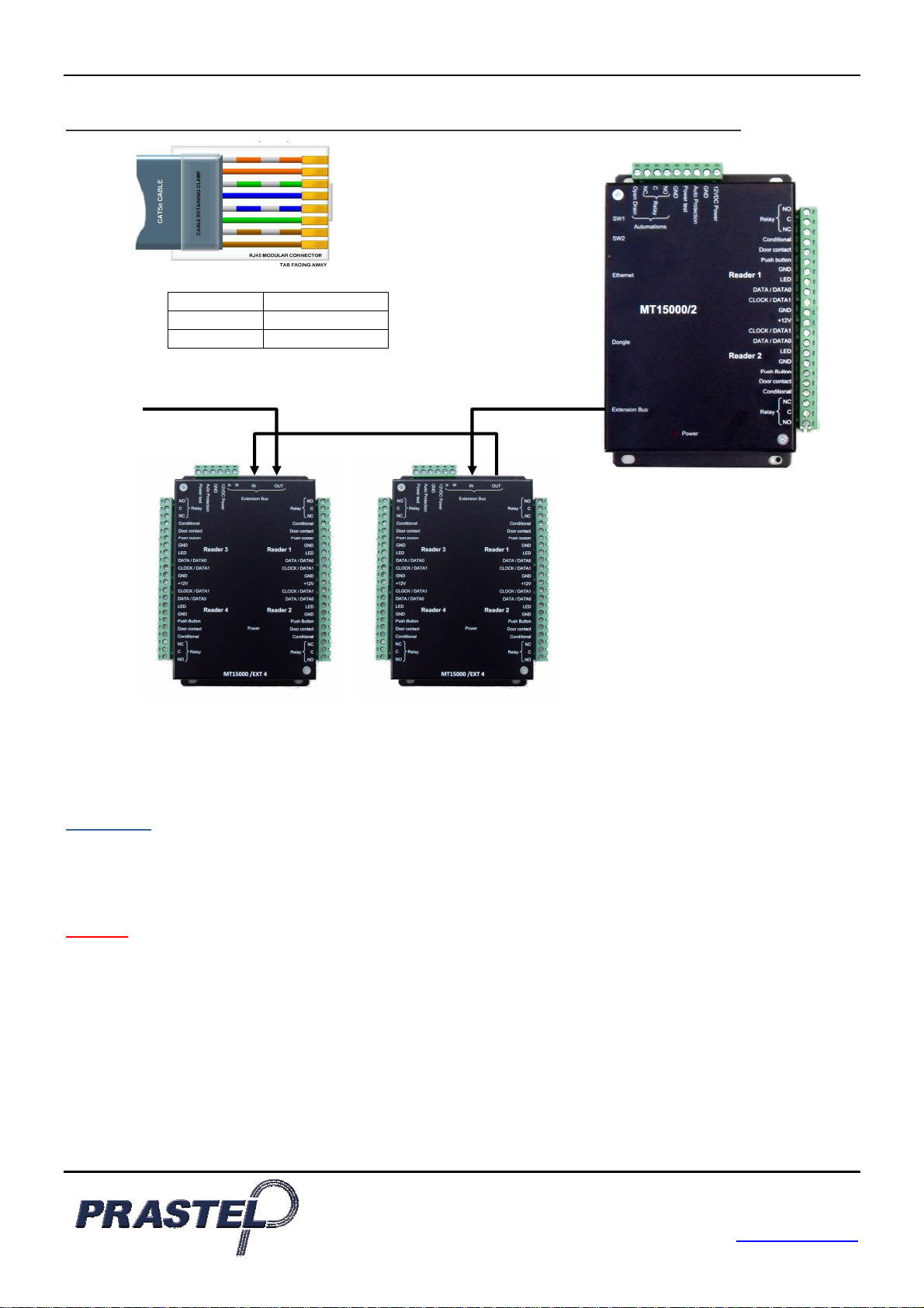
Wiring recommendations: the cables used to connect readers, network and other devices must be installed in
accordance with the instructions for Level 2, as set forth in standard NF EN 61000-4-4 (protected environment).
This product must be installed by a qualified company. Inappropriate installation and use may entail a risk of
electric shock or fire. Please read these technical instructions before installing the product and follow assembly
instructions thereof.
All internal capacitors in the 220V version will lose charge at a healthy level after 60 seconds once power
has been turned off, under normal conditions. However, in the event of a failure, the charge may be main-
tained for much longer and adequate precautions are required before using the product.
SPECIFICATIONS
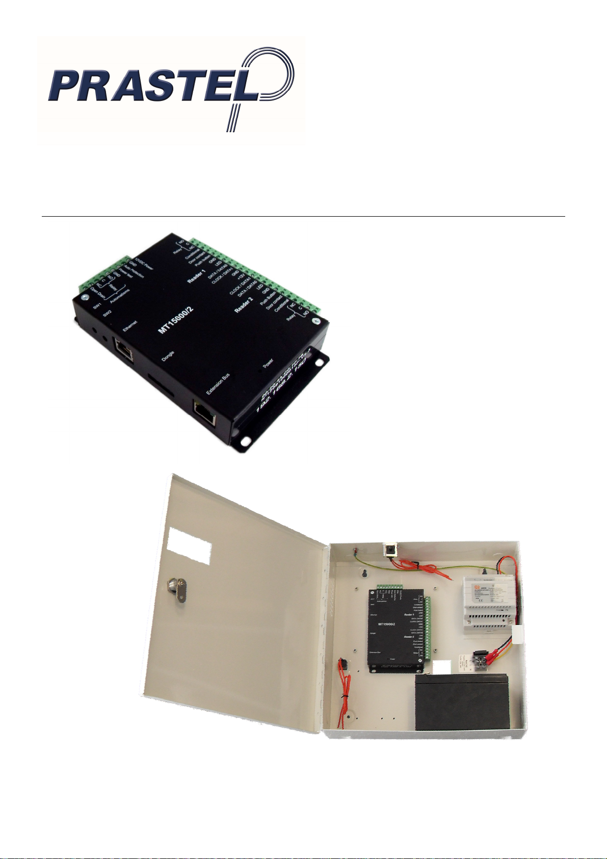
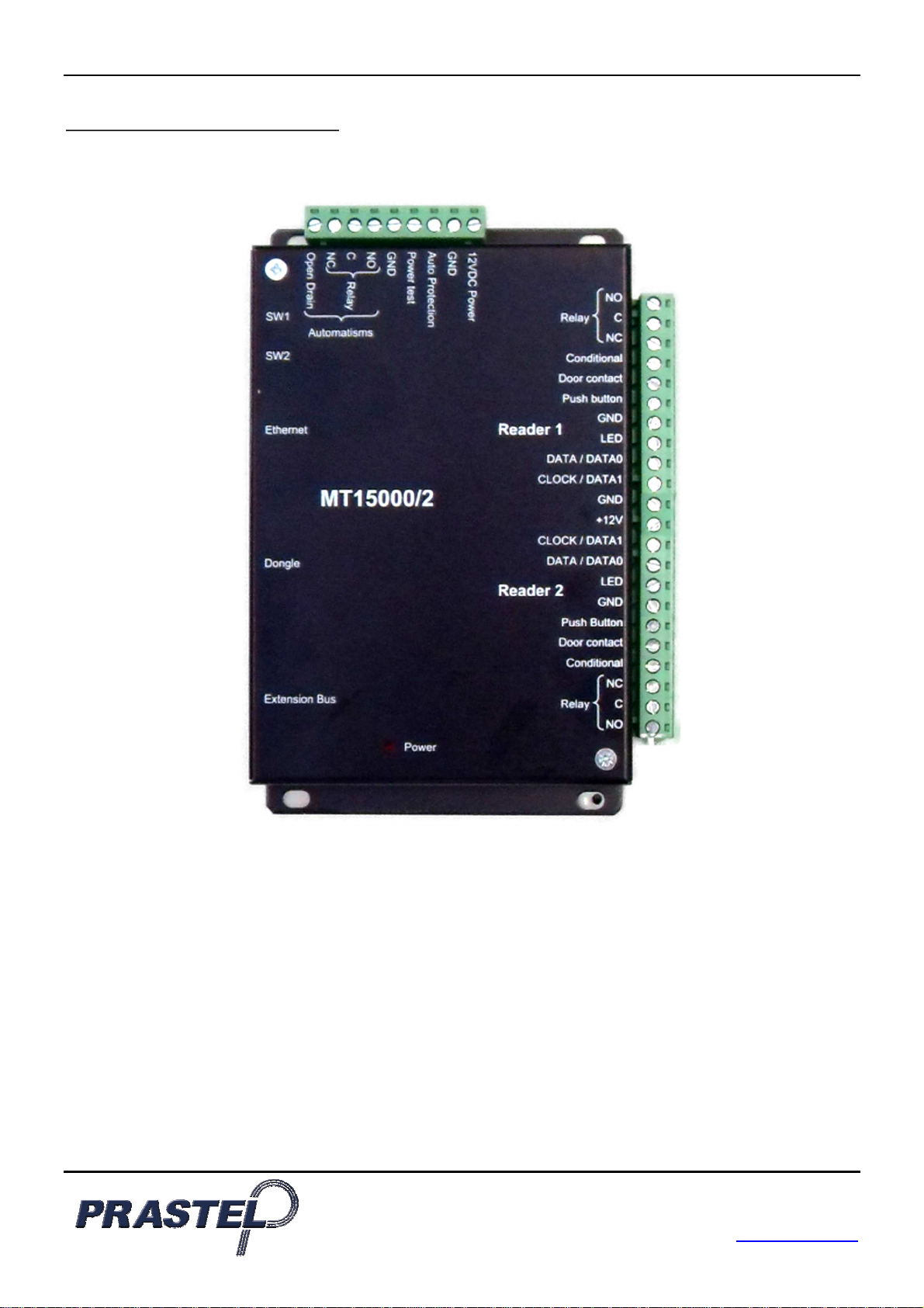
1) MT15000/2
Maximum consumption............................... 300 Ma
Power voltage ............................................. 9 – 14VDC
Weight ........................................................ 150 g
Dimensions.................................................157 x 108 x 30 mm
Operating temperature................................ - 20°C to + 50°C
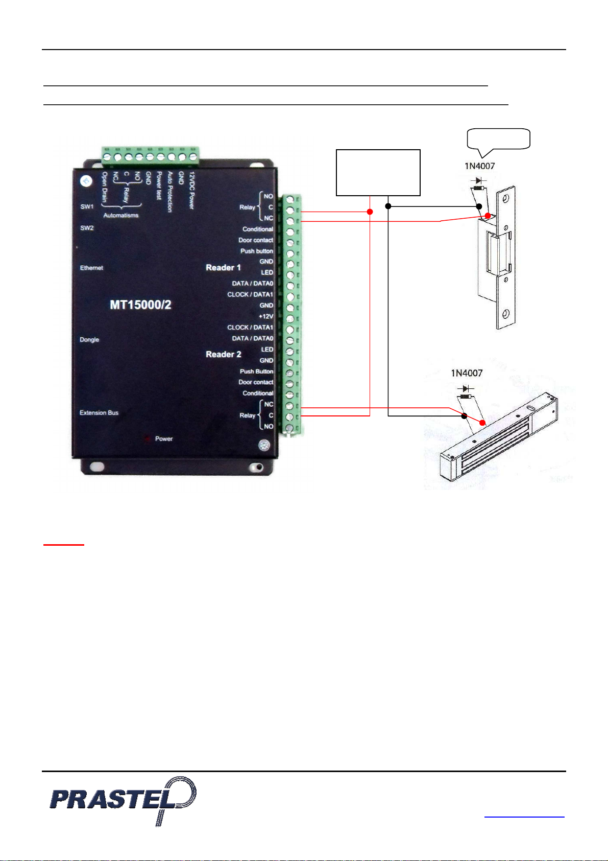
Relay outputs.............................................. 1A / 12V – 1A / 24V
2) MT15000/2-M
Weight, with housing...................................4 Kg
Housing dimensions ...................................330 x 330 x 90 mm
Operating temperature................................ - 20°C to + 50°C
Integrated 220V power supply:
Output voltage............................................. 12V
Maximum output current............................. 5A
Battery connection...................................... 13,6V
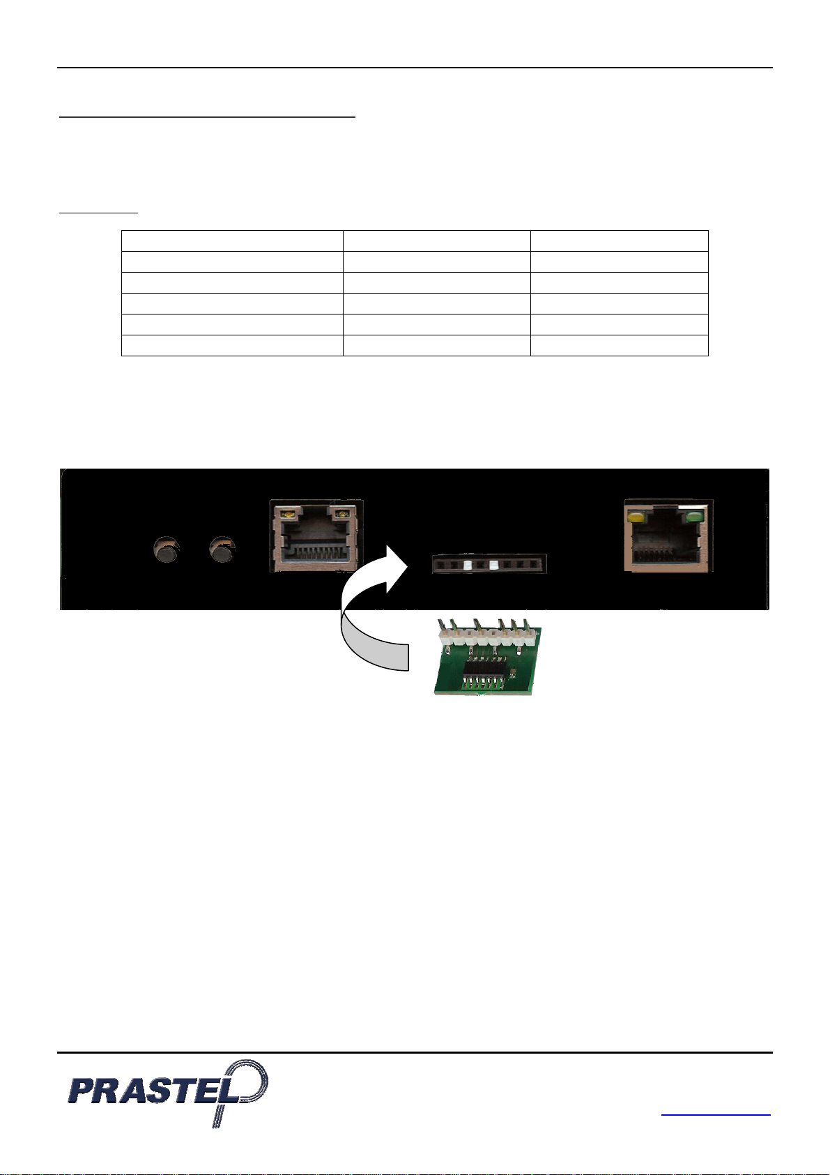
3) PROTECTION
The control unit is fitted with a fuse on 12V input inside the housing. Check the fuse if the power LED does not light
up when the module is under power.