manuals.online logo
Brands
  1. Home
  2. •
  3. Brands
  4. •
  5. Honeywell
  6. •
  7. Control Unit
  8. •
  9. Honeywell TM300 User manual

Honeywell TM300 User manual

TM300 / KB191
Einbau-Anleitung .Installation Instructions .Instructions de montage
Installatievoorschrift .Istruzioni per il montaggio .Instrucciones de instalación
KB191
Kaltwasserbremse
Non-return valve for cold water
Clapet de non-retour pour eau froide
Koudwaterslagklep
Freno idraulico per acqua fredda
Válvula antirretorno
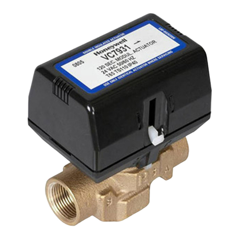
TM300
Thermostatischer Wassermischer
Thermostatic Mixing Valve for domestic water
Mitigeur thermostatique pour eau domestique
Thermostatische mengkraan
Miscelatore termoststico per acqua servici
Válvula mezcladora termostática
EB-TM300=B
MU1H-1327GE23 R0303
Automation and Control Products
Honeywell AG Phone: (49) 6261 810
Hardhofweg Fax: (49) 6261 81309 www.honeywell.de/haustechnik
D-74821 Mosbach [email protected] http://europe.hbc.honeywell.com
Verwendungsbereich
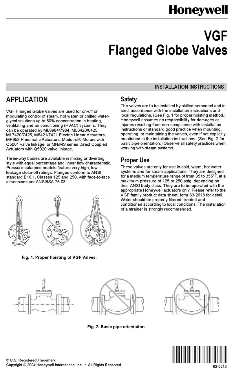
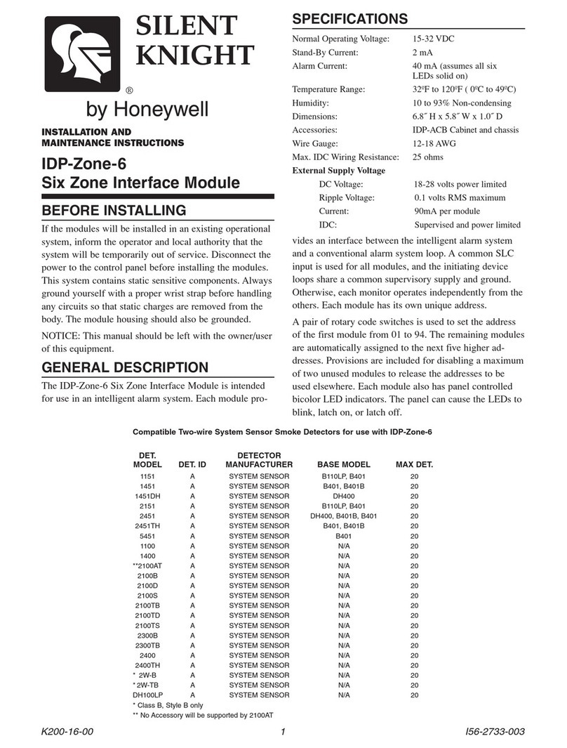
Thermostatische Wassermischer TM300 dienen
zur Regelung der Wassertemperatur
●in Warmwasserbereitungsanlagen an zentraler
Stelle (Abb. 2), dezentral an der Entnahme-
stelle (Abb. 3) oder in solarbetriebenen,
bivalenten Warmwasserbereitern (Abb. 6)
●in Heizungsanlagen bei Fußbodenheizungen
(Abb. 4) oder zur Begrenzung der Kessel-
rücklauftemperatur (Abb. 5).
Bei Warmwasserbereitungsanlagen muss in der
Zirkulationsleitung eine Kaltwasserbremse KB191
(Abb 2-3) eingebaut werden, die verhindert, dass
an den Zapfstellen Kaltwasser über die Zirkulations-
leitung beigemischt wird.
Einbau
Als Mischventil:
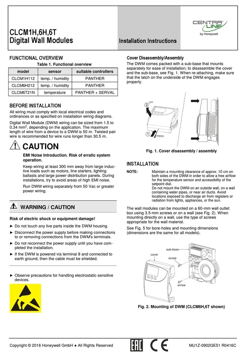
Beim Anschluss an die Warm- und Kaltwasser-
leitung muss die Durchflußrichtung mit den Pfeilen
auf dem Gehäuse übereinstimmen.
AlsVerteilventil:
Das Ventil wird hier im Vergleich zum Misch-
ventil umgekehrt durchströmt. Durchströmung
entgegen den Pfeilen auf dem Gehäuse.
Ventileinstellung ändern (Abb. 7)
Die Mischwassertemperatur kann im Bereich von
30 °C bis 60 °C eingestellt werden. Hierzu die
Schutzkappe abnehmen. Um die Temperatur zu ver-
ändern, das Einstellrad drehen, bis die gewünsch-
te Temperaturkennzahl mit der Markierung 8
übereinstimmt.
Technische Daten
Betriebsdruck max. 10 bar
Temperatur max. 90 °C
Einstellbereich 30 °C - 60 °C
Zapfmenge bei ∆p = 1 bar
ca 40 l/min
Maximale Druckdifferenz 2,5 bar
Zur Vermeidung des Legionellenwachstums soll
nach DVGW-W551 und W552 das Wasservolumen
in der Rohrleitung zwischen Mischarmatur und
entferntester Entnahmestelle nicht größer als
3 Liter sein. Dies bedeutet eine max. Leitungs-
länge von 10 m bei 3/4" (20 mm) und 17 m bei 1/2"
(15 mm).
D
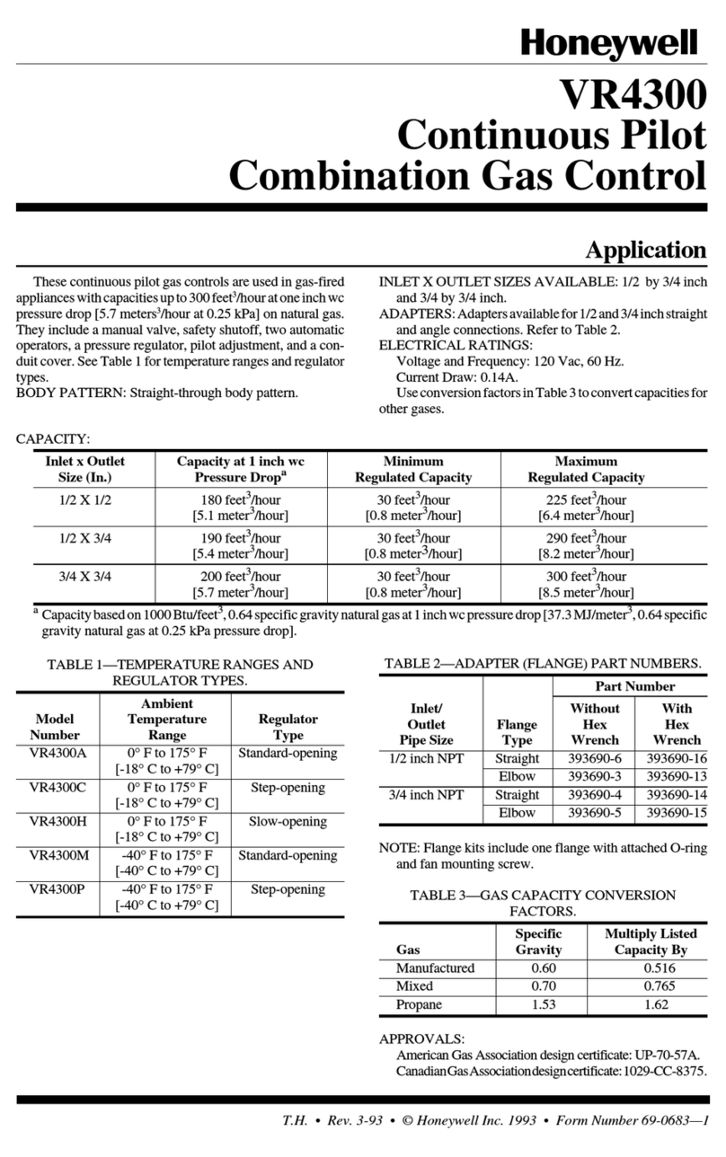
Kaltwasserbremse KB191-3/4
Für Wasseranlagen mit thermisch
geregelten Wassermischern. Sie wird
in die Zirkulationsleitung eingebaut
und verhindert, dass an den Zapfstellen
Kaltwasser beigemischt wird (Abb.2-3).
Betriebsdruck max. 10 bar
Temperatur max. 90 °C
Einbaulage Pfeil in Fließrichtung
H= Warmwasser
Warm water
Eau chaude
Warmwater
Acqua calda
Agua caliente
CH
MIX
C= Kaltwasser
Cold water
Eau froide
Koudwater
Acqua fredda
Agua fría
7
5
4
23
1
MIX =
Mischwasser
Mixed water
Eau mitigée
Mengwater
Acqua milcelta
Agua mezclada
8
SG160
1/2" max 17 m
3/4" max. 10 m
KB191
SG160
1/2" max 17 m
3/4" max. 10 m
SG160
6
VT100
VT100
RV281
RV284
CH
MIX
▲
2 3
F
Frein hydraulique KB191-3/4
Destiné aux installations d'eau chaude
munies de mitigeurs thermostatiques. Il
est incorporé dans le circuit et empêche
l'eau froide de pénétrer dans le circuit aux
points de captage (fig. 2-3).
Pression de service max. 10 bar
Température max. 90°C
Position de montage Flèche dans le
sens d'écoulement
INL
Toepassingsgebied
Thermostatische mengkranen TM300 dienen voor
het regelen van de watertemperatuur:
●in warmwaterinstallaties in centrale positie (fig. 2),
in gedecentaliseerde positie op plaatsen, waar
water getapt wordt (fig. 3) ofwei in door zonne-
warmte aangedreven, bivalente warmwater-
installaties (fig. 6)
●i
n verwarmingsinstallaties voor vloerverwarming
(fig. 4) ofwel ter beperking van de temperatuur
van het naar de ketel teruggevoerde water (fig. 5)
Bij installaties voor de huishoudelijke warmwater-
voorziening dient er in de buisleiding een koud-
waterafsluiter KB191 (fig. 2-3) te worden aange-
bracht, die verhindert, dat op plaatsen, waar water
getapt wordt, koud water via de buisleiding aan
het warmwatermengsel wordt toegevoegd.
Montage Als mengkranen:
Bij het aansluiten op de warm- en koudwater-
leiding dient de doorstroomrichting met die van de
pijlen op het klephuis overeen te komen.
Als verdeelklep:
Vergeleken met de mengkraan, stroomt in de
verdeelklep het water in omgekeerde richting
en wel tegenovergesteld aan de op het
klephuis aangegeven pijlrichting.
Wijziging van de klepregeling (fig. 7)
De mengwatertemperatuur kan over een schaal
van 30°C tot 60°C worden geregeld.Hiertoe dient
men de beschermingsdop te verwijderen en de
instelknop te draaien totdat het gewenste tempe-
ratuurcijfer met het merkteken 8 overeenstemt.
Technische gegevens
Bedrijfsdruk max. 10 bar
Temperatuur max. 90 °C
Instelschaal 30 °C - 60 °C
Aftapbaar volume bij ∆p = 1 bar ca 40 l/min
Maximum drukverschil 2,5 bar
Teneinde de ontwikkeling van legionellen te
voorkomen, dient volgens DVWG-W551 enW552
het watervolume in de buisleiding tussen
mengapparatuur en het verst afgelegen aftappunt
niet meer dan 3 liter te bedragen. Dat betekent
een max. buislengte van 10 m bij 3/4" (20 mm) en
17 m bij 1/2" (15 mm).
Campo d'impiego
I miscelatori termostatici TM300 servono per
regolare la temperatura dell'acqua:
●in impianti acqua servizi, in posizione centra-
lizzata(fig. 2), in posizione decentraizzata nel
punto di prelievo (fig.3) oppure in impianti
acqua servizi bivalenti di tipo solare (fig. 6)
●in impianti acqua servizi che servono per il
riscaldamento del suolo (fig. 4) o per limitare la
temperatura di ritorno (fig.5).
Per quanto riguarda impianti acqua servizi è neces-
sario inserire nella conduttura di circolazione un
freno idraulico per acqua fredda KB191 (fig. 2-3) il
quale impedisce che, in punti di prelievo, acqua
fredda penetri in miscela attraverso la conduttura
di circolazione.
Montaggio Come miscelatore:
Al momento del raccordo alla conduttura dell'acqua
calda e fredda è necessario che la direzione flusso
corrisponda alle frecce sul corpo della valvola.
Come distributore:
In paragone al miscelatore, la valvola lascia pas-
sare l'acqua in senso inverso. Flusso in senso
opposto alle frecce sul corpo della valvola
Modifica della regolazione (fig. 7)
La regolazione della temperatura dell'acqua
miscelata si effettua dentro un campo di regolazione
da 30°C a 60°C. A tal fine rimuovere la calotta di
protezione e cambiare la temperatura, ruotando la
manopola finchè la cifra della temperatura
desiderata non apparisca in fronte dell'indice 8 .
Dati tecnici
Pressione di esercizio max. 10 bar
Temperatura max. 90 °C
Campo di regolazione 30 °C - 60 °C
Portata prelevabile per ∆p = 1 bar ca 40 l/min.
Differenza di pressione
massima 2,5 bar
Allo scopo di prevenire lo sviluppo di legionelle, il
volume dell'acqua tra il miscelatore ed il punto di
prelievo più remoto secondo DVGW-W551 e W552
non potrà superare 3 litri. Questo significa una
tubazione lunga max. 10 m per 3/4" (20 mm) e 17
m per 1/2" (15 mm).
Koudwaterafsluiter KB191-3/4
Ten behoeve van waterinstallaties met
thermostaatmengkranen. Deze wordt
in de buisleiding ingebouwd en verhin-
dert, dat op plaatsen, waar water getapt -
wordt, koud water aan het warmwater-
mengsel wordt toegevoegd (fig 2-3).
Bedrijfsdruk max. 10 bar
Temperatuur max. 90 °C
Stand bij de montage pijl volgens stroming
Freno idraulico per acqua fredda KB191-3/4
Per impianti acqua servizi con miscelatori
termostatici. Esso viene inserito nella con-
duttura di circolazione e impedisce che,
nei punti di prelievo, l'acqua fredda penetri
in miscela (fig. 2-4).
Pressione di esercizo max. 10 bar
Temperatura max. 80 °C
Posizione di montaggio freccia in senso flusso
Domaine d'application
Les mitigeurs thermostatiques TM300 servent à
régler la température de l'eau:
●dans les installations d'eau chaude sanitaire en
position centrale (fig. 2), au point de captage en
position décentralisée (fig. 3) ou encore dans
les installations génératrices d'eau chaude
bivalentes de type solaire (fig. 6)
●dans les installations destinées à chauffer le sol
(fig. 4) ou pour limiter la température de retour
de la chaudière (fig. 5).
Pour ce qui est des installations généatrices d'eau
chaude sanitaire, il faut incorporer un frein
hydraulique KB191 (fig. 2-3) dans le circuit et ce
afin d'empêcher que de l'eau froide pénètre dans
le circuit aux points de captage.
Montage
Comme mitigeur:
Lors du raccordement au circuit d'eau chaude et
d'eau froide veiller à ce que le sens de l'écoulement
corresponde aux flèches sur le corps de vanne.
Comme vanne distributrice:
Comparée au mitigeur la vanne laisse passer
l'eau en sens inverse. Le sens d'écoulement
est opposé à celui indiqué par les flèches sur
le corps de vanne.
Modification du réglage (fig. 7)
La température de l'eau mitigée se règle dans une
plage de 30°C à 60°C.Pour ce faire, enlever le
capuchon de protection et tourner le bouton de réglage
jusqu'à ce que le chiffre indiquant la température
souhaitée apparaisse en face de l'indice 8 .
Spécifications
Pression de service max. 10 bar
Température max. 90 °C
Plage de réglage 30 °C - 60 °C
Volume captable pour ∆p = 1 bar
environ 40 l/min
Différence de pression maxi 2,5 bar
Afin d'éviter le développement de légionelles, le
volume d'eau entre le mélangeur et le point de
prélèvement le plus éloigné d'après DVGW-W551 e
W552, ne pourra pas dépasser les 3 litres. Cela
signifie une longueur de tube maximale de 10 m
pour 3/4" (20 mm) et de 17 m pour 1/2" (15 mm )
GB
Purpose
TM300 thermostatic mixing valves provide control
of the water temperature:
●For centralised control on hot water supply units
(fig. 2) or for localised control adjacent to point-
of-use outlets (fig. 3). Or for solar-heated hot water
units with dual energy source (fig. 6)
●In heating systems with underfloor heating (fig. 4)
or for limiting boiler return temperatures (fig. 5).
Where a hot water supply system includes a
secondary circulation circuit, a KB191 return flow
retarder unit must be fitted (figs. 2 and 3) to
prevent cold water backfeeding and cooling the
mixed water at the outlets.
Installation
As a mixing valve:
The flow direction arrows must be observed when
connecting the hot and cold water inlets.
As a diverter valve:
For this application flow is in the reverse
direction and therefore is in the opposite
direction to the arrows on the housing.
Changing the setting (fig. 7)
The mixing valve can be set within the range 30°C
to 60°C as follows: Remove the protective cap. Turn
the adjuster knob until the required setting number
aligns with the index mark 8 on the valve body.
Technical data
Operating pressure Maximum 10 bar
Installation orientation As required
Hot water inlet temperature Maximum 90°C
Setting range 30°C to 60°C
Flow rate ar 1.0 bar pressure
differential across valve
approximately 40 litres/min
Maximum differential pressure
across valve 2.5 bar
To prevent the growth of legionella, DVGW-W551
and W552 specify that the water volume in the
pipework between the mixer valve and the furthest
take-off point should not exceed 3 litres. This
corresponds to a maximum length of 10 metres for
3/4"(20 mm) pipework and 17 metres for 1/2" (15 mm)
Return flow-retarder unit KB191-3/4
For fitting to systems which include a
hot water secondary circulation circuit to
prevent cold water backfeeding and
cooling the mixed water at the
outlets (figs. 2 and 3).
Operating pressure Maximum 10 bar
Operating temperature Maximum 90°C
Installation orientation Vertical with flow
direction arrow
pointing downwards
4 5
E
Aplicación
Las válvulas mezcladoras termostáticas TM300,
se emplean para controlar la temperatura del agua:
●en instalaciones de agua caliente sanitaria, en
un punto centralizado (Fig. 2), en las zonas de
consumo (Fig. 3) o en sistemas con apoyo de
energía solar (Fig. 6).
●en instalaciones de calefacción por suelo
radiante (Fig.4) o para limitar la temperatura de
retorno a caldera (Fig. 5).
En las instalaciones en las que hay circuito de
recirculación, debe instalarse la válvula
antirretorno KB191 (Figs.2 y 3) para evitar que el
agua fría entre en el circuito de ida del agua
caliente a través del retorno.
Instalación
Como válvula mezcladora.
Debe tenerse en cuenta el sentido de la flecha al
conectar las entradas de agua caliente y fría.
Como válvula distribuidora.
Para esta aplicación el caudal viene en
sentido contrario y por tanto opuesto al
indicado por la flecha.
Modificación de la regulación.
La temperatura puede regularse entre 30ºC y 60ºC
de la siguiente manera: Quitar la tapa protectora.
Girar el botón de ajuste hasta que la temperatura
de regulación deseada se alinee con la marca 8
en el cuerpo de la válvula.
Datos técnicos
Presión de trabajo 10 bar máx.
Orientación en instalación Como se requiera
Entrada agua caliente 90°C máx.
Margen de regulación 30°C a 60ºC
Caudal aproximado con una
presión diferencial de 1,0 bar 40 litros/minuto
Presión diferencial máxima
a través de la válvula 2,5 bar
Para prevenir el desarrollo de legionela, DVGW-
W551 y W552 especifica que el volumen de agua
en la instalación, entre la válvula y el siguiente
punto de suministro, no debe exceder de 3 litros.
Esto corresponde a una longitud máxima de 10
metros para tubo de ¾" (20mm) y 17 metros para
tubo de ½" (15mm).
Válvula antirretorno KB191-3/4
Instalar en circuitos con recirculación
de agua caliente para prevenir el
retorno de agua fría y que esta enfríe
el agua mezclada en las salidas
(Figs. 2 y 3).
Presión de trabajo 10 bar máx.
Temperatura de trabajo 90°C máx.
Orientación en instalación Vertical con la flecha
de dirección de flujo
hacia abajo.
Sicherheitshinweise
Der Wassermischer TM300 benötigt wie alle
Regelarmaturen eine gewisse Zeit, um plötz-
liche Änderungen der Betriebsbedingungen
einzuregeln. Dies tritt vor allem dann auf, wenn
keine Zirkulationsleitung vorhanden ist und
die Vorlaufleitung auf Raumtemperatur aus-
kühlen kann. Beim Zapfen von Wasser wird
dann das Regelelement plötzlich mit dem
heißen Vorlaufwasser beaufschlagt. Dadurch
kann es zu einem kurzfristigen Überschwingen
der eingestellten Sollwerttemperatur kommen.
Safety comment
Just as all other controls, the water mixing
valve TM300 needs some time to respond to
sudden changes in the operating conditions.
This will mainly occur, if there is no circulat-
ing system so that the flow piping cools down
to room temperature, When drawing off water,
the control will suddenly be in touch with the
hot-water flow and as a result temperature
may exceed its set-point value during a short
period.
Note de sécurité
De la même façon que tous les autres disposi-
tifs de régulation, la vanne mélangeuseTM300
a besoin d'un certain temps pour s'adapter
aux brusques changements des conditions
de service. Cela se produira surtout lorsqu'il
n'y a pas de circuit de circulation et que la
conduite de départ refroidit à la température
ambiante. Lors des piquages le dispositif de
contrôle entre tout à coup en contact avec
l'eau chaude de départ de sorte que pendant
un bref instant la témperature puisse dépas-
ser sa valeur de consigne.
D
GB
F
Veiligheidsopmerking
Net als alle andere regelorganen, heeft
mengklep TM300 een bepaalde tijd nodig om
zich op plotselinge wijzigingen in de
bedrijfscondities in te kunnen stellen. Dit kan
zich vooral dan voordoen, indien er geen
circulatiesysteem aanwezig is, zodat de
toevoerleiding op kamertemperatuur afkoelt.
Tijdens het aftappen van water komt het
regelorgaan dan ineens met het toegevoerde
hete water in aanraking, waardoor de
temperatuur gedurende een kort ogenblik
boven het ingestelde temperatuurpeil kan
stijgen.
Nota di sicurezza
Proprio come tutti gli altri dispositivi di
regolazione, la valvola miscelatrice TM300
avrà bisogne di qualche tempo per addatarsi
alle variazioni subitanee delle condizioni di
funzionamento.Ciò potrebbe avvenire
sopratutto quando non c'è un circuito di
circolazione e la tubatura dell'acqua di
partenza si raffredda alla temperature
ambientale. Durante la presa d'acqua il
dispositivo di regolazione si scontra di colpo
con l'acqua calda di partenza in modo tale
che durante un breve momento la
temperatura possa eccedere il suo punto di
consegna.
Nota de seguridad
Como en otros dispositivos de control la
válvula mezcladora TM300 necesita un
tiempo de respuesta ante cambios
repentinos en las condiciones de trabajo.
Esto suele ocurrir cuando no hay instalado
un circuito de recirculación y la temperatura
del agua de la tubería se enfría hasta la
temperatura ambiente. Cuando se inicia el
consumo de agua, el dispositivo de
regulación entra en contacto, de golpe, con
el agua caliente, por lo que durante unos
instantes la temperatura de mezcla puede
exceder la temperatura de consigna.
NL
I
E

This manual suits for next models

1

Other Honeywell Control Unit manuals

Honeywell 4219 Assembly instructions

Honeywell

Honeywell 4219 Assembly instructions

Honeywell CA295 User manual

Honeywell

Honeywell CA295 User manual

Honeywell SILENT KNIGHT SK-Control-6 User manual

Honeywell

Honeywell SILENT KNIGHT SK-Control-6 User manual

Honeywell VGF21 Operation manual

Honeywell

Honeywell VGF21 Operation manual

Honeywell CentraLine CLIOL822A Operation manual

Honeywell

Honeywell CentraLine CLIOL822A Operation manual

Honeywell VR8205 User manual

Honeywell

Honeywell VR8205 User manual

Honeywell Elster Jeavons S100 User manual

Honeywell

Honeywell Elster Jeavons S100 User manual

Honeywell V4297S Operation manual

Honeywell

Honeywell V4297S Operation manual

Honeywell 2MLL-PMEC User manual

Honeywell

Honeywell 2MLL-PMEC User manual

Honeywell D22 User manual

Honeywell

Honeywell D22 User manual

Honeywell ST7700 User manual

Honeywell

Honeywell ST7700 User manual

Honeywell MI-DCZME User manual

Honeywell

Honeywell MI-DCZME User manual

Honeywell VCZA Series User manual

Honeywell

Honeywell VCZA Series User manual

Honeywell PW6K1R1E Operator's manual

Honeywell

Honeywell PW6K1R1E Operator's manual

Honeywell Resideo ADEMCO 4101SN V-Plex Assembly instructions

Honeywell

Honeywell Resideo ADEMCO 4101SN V-Plex Assembly instructions

Honeywell Pro-Watch 7000 User manual

Honeywell

Honeywell Pro-Watch 7000 User manual

Honeywell 026593.10 Instruction manual

Honeywell

Honeywell 026593.10 Instruction manual

Honeywell 7800 SERIES User manual

Honeywell

Honeywell 7800 SERIES User manual

Honeywell 7800 SERIES Operation manual

Honeywell

Honeywell 7800 SERIES Operation manual

Honeywell CF4680 User manual

Honeywell

Honeywell CF4680 User manual

Honeywell CentraLine CLCM1T User manual

Honeywell

Honeywell CentraLine CLCM1T User manual

Honeywell BA295S User manual

Honeywell

Honeywell BA295S User manual

Honeywell W7212 Operation manual

Honeywell

Honeywell W7212 Operation manual

Honeywell Maxon SMA11 User manual

Honeywell

Honeywell Maxon SMA11 User manual

Popular Control Unit manuals by other brands

Haldex L31045 Repair instructions

Haldex

Haldex L31045 Repair instructions

TP-Link TL-SM321A installation guide

TP-Link

TP-Link TL-SM321A installation guide

WAGO 750-651 manual

WAGO

WAGO 750-651 manual

SMC Networks VS7-6 Series instruction manual

SMC Networks

SMC Networks VS7-6 Series instruction manual

AKG AMM 10 - quick start guide

AKG

AKG AMM 10 - quick start guide

Matrix Orbital LCD0821 user manual

Matrix Orbital

Matrix Orbital LCD0821 user manual

Lunt Solar Systems PC-USB instruction manual

Lunt Solar Systems

Lunt Solar Systems PC-USB instruction manual

Danfoss PVG 16 PVH/Covers technical information

Danfoss

Danfoss PVG 16 PVH/Covers technical information

Honeywell Home NK300SE-VE Product specification sheet

Honeywell Home

Honeywell Home NK300SE-VE Product specification sheet

Farho MI Farho VIC Quick installation guide

Farho

Farho MI Farho VIC Quick installation guide

Fema S40-T user manual

Fema

Fema S40-T user manual

VPro SR instruction manual

VPro

VPro SR instruction manual

Maxon ESCON 24/2 Hardware reference

Maxon

Maxon ESCON 24/2 Hardware reference

Elko iNels RFATV-2 quick start guide

Elko

Elko iNels RFATV-2 quick start guide

Kemo M148N manual

Kemo

Kemo M148N manual

DSC PC5700 installation instructions

DSC

DSC PC5700 installation instructions

V2 CU1 manual

V2

V2 CU1 manual

Taco Comfort Solutions 5000-3 Series instruction sheet

Taco

Taco Comfort Solutions 5000-3 Series instruction sheet

manuals.online logo
manuals.online logoBrands
  • About & Mission
  • Contact us
  • Privacy Policy
  • Terms and Conditions

Copyright 2025 Manuals.Online. All Rights Reserved.