1
A Honeywell Company
EN1C-0131SZ20 R0305
INTRODUCTION
The burner control box DMG 973 controls and supervises
power burner for gas and dual fuel. The control box is
currently under approval according the relevant European
standards. The use on direct air heaters according DIN 4794
is also possible.
With the facility to connect an air damper unit, a 2 stage
operation with two fuel valves or a modulating operation
with one fuel valve is possible.
The microprocessor- based programming sequence ensu-
res extremely stable timings independent of voltage varia-
tions, ambient temperature and/or switch-on cycles. The
built-in information system not only provides a continuous
monitoring of the actual state of the box (very helpful es-
pecially for monitoring the start-up phase) but also informs
about the cause of a possible lock out. The lock out cause
is stored in such a way that it can be retrieved even after a
power failure.
The control box is designed for maximum safety in case of
fluctuations in the voltage supply. If the mains voltage drops
below the permitted level, operation is interrupted and the
control box automatically prevents the start sequence from
being repeated. In this way, the safety of the system is not
put at risk by a drop in the mains voltage. This low-voltage
protection works not only during start-up but also perma-
nently during operation.
CONSTRUCTIONAL FEATURES
Microprocessor, electronic components, output relais and
flame amplifier are placed on two printed circuit boards.
These plus the lockout- and reset circuit are well protected
inside a flame resistant, plug-in type plastic housing.
The reset switch for reset / remote lockout with its built-in
LED for displaying the information system plus the central
fixing screw are placed on top of the housing.
The wiring base S98 is equipped with spare- and
extraterminals and allows together with a variety of cable
entry points utmost flexibility of electrical wiring.
The DMG 973 is funstionally compatible to MMI 813 and
MMI 813.1
Please note: Is the DMG 973 to be used to
replace the MMI 813 or 813.1, care has to be
taken to make sure the air proving switch (LW) is
wired between terminals 4 and 7 and not like on
the MMI between 5 and 7.
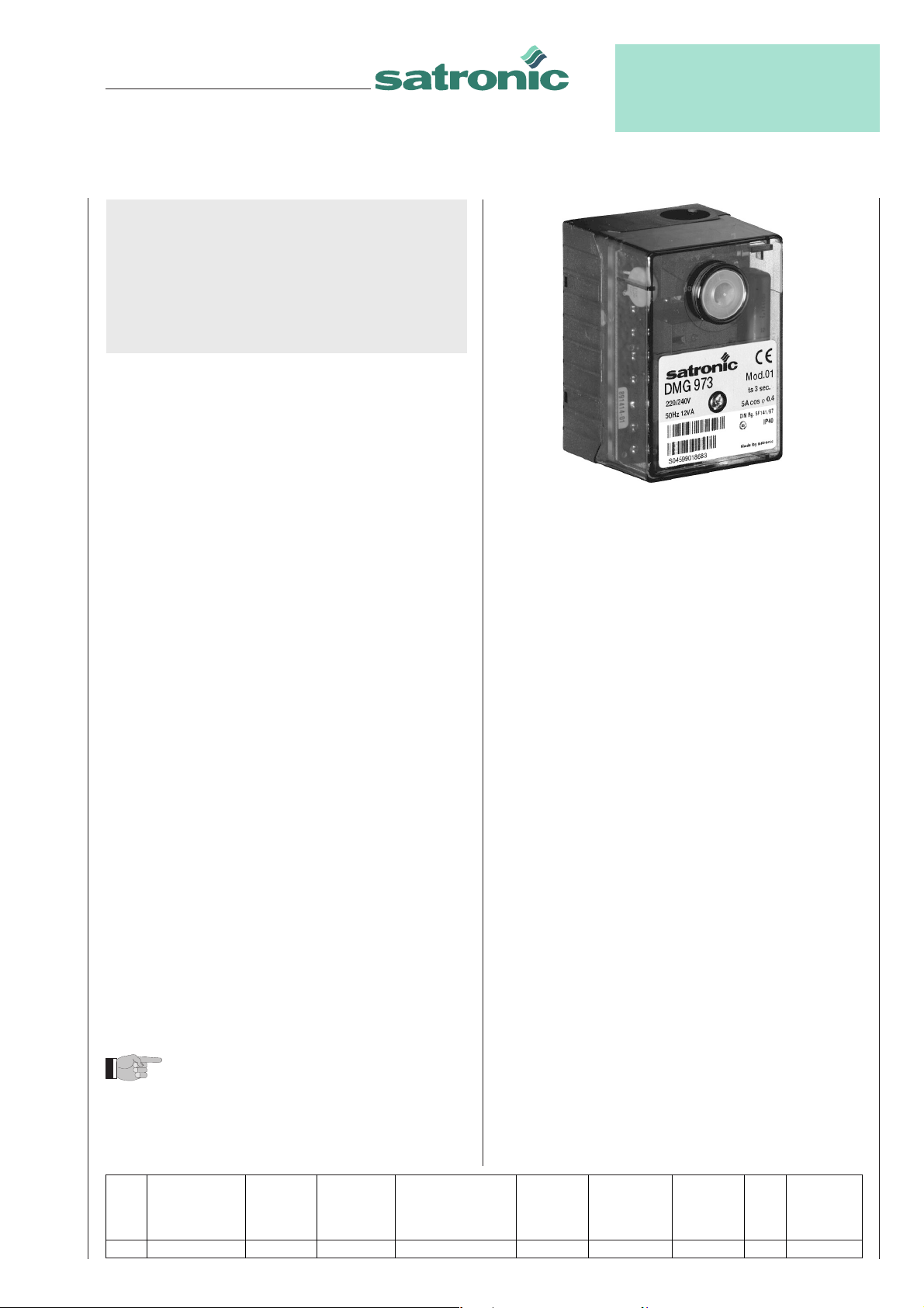
DMG 973
Gas Burner Safety Control
For 2-stage forced draught and combi
oil/gas burners, facility to connect an air
damper unit
Possible flame detectors:
- Ionisation probe
- Infrared flicker detector 1020.1
- UV flame sensor UVD 971
TECHNICAL DATA
Operating voltage 220 / 240 V (-15... +10%)
50 Hz ( ±5%)
or 110 / 120 V (-15... +10%)
60 Hz ( ±5%)
Fuse rating 10 A fast, 6 A slow
Power consumption ca. 12 VA
Max. load per output
- term. 3 ignition trafo 1.5 A, cos ϕ 0.2
- term. 4 motor 2.0 A, cos ϕ0.4
- term. 5 + 6 solenoid valves 1.0 A, cos ϕ 0.4
- term. C air damper 1.0 A, cos ϕ0.4
- term. B alarm indicator 1.0 A, cos ϕ0.4
total load 5.0 A, cos ϕ0.4
max. 20 A during 0.5 sec
Direct lockout after a loss-of-flame during operation
Air proving switch 1 working contact 4 A, 230V
Sensitivity (operation) 1 µA
Min. required ion. current 1.5 µA
Sensitivity for stray light 0.4µA
Ionisation probe insulation Probe - earth
greater than 50 MΩ
stray capacity Probe - earth
less than 1000 pF
cable lenght < 3 m
Flame detectors
IRD 1020.1 side-on or end-on viewing
UVD 971 end-on viewing
Weight incl. Wiring base 190 g
Mounting position any
Protection class IP 40
Approved ambient parameter
for control and flame detector max. 95% at 30°C
- for operation -20°C... +60°C
- for storage -20°C... +80°C
Build-up of ice, penetration of
water and condensing water are inadmissible
Approvals according
to European standards EN 298 and EN 230, as
well as all other relevant
Directives and standards
Classified acc. to EN 298 FTLLXN
Model max. reaction supervised pre-ignition LK-open command LK-close post-ignition Stray light safety delay
time for air pre-purge time during pre-purge movement time monitoring time terminal 6/C
proving switch time
tlw tv1 tvz tkl tr tn tf ts tv2
01 60 44 3 36 8 2,5 5 3 6
Table of timings (sec.)


