manuals.online logo
Brands
  1. Home
  2. •
  3. Brands
  4. •
  5. Honeywell
  6. •
  7. Security Camera
  8. •
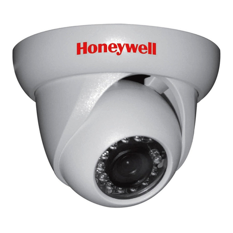
  9. Honeywell HD55IP User manual

Honeywell HD55IP User manual

Document 800-09309V1 – Rev A – 01/12
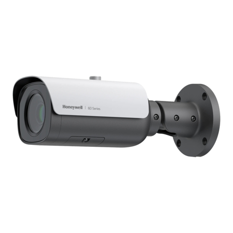
Performance Series
Rugged Day/Night H.264 IP Dome Camera
Quick Install Guide
Introduction
Thank you for purchasing a Honeywell Performance Series Rugged Day/Night IP Dome
Camera. Before installing the camera, please read this guide carefully and verify your model:
HD55IP/HD55IPX, 720p resolution, 3.3 - 12 mm Vari-focal Auto Iris lens
HD54IP/HD54IPX, VGA resolution, 3.3 - 12 mm Vari-focal Auto Iris lens
For detailed information for your specific camera, please refer to the appropriate user guide
located on the IP Utility DVD or on the Honeywell product web site.
Before installing, Honeywell recommends that you download the latest software updates. Go
to www.honeywellsystems.com/support/download-center/index.html and follow the
instructions on the page to log on, find your camera, and then download the latest software
updates.
Preparing the Mounting Surface
Note To prevent moisture from entering the housing, position the enclosure with the side conduit entry
pointing down.
Note The housing is intended for mounting on a flat surface only.
1. Use the mounting template to mark the mounting surface for the screw and cable access holes.
2. Pre-drill holes in the mounting surface,
as required.
Installing the Conduit Plug
The camera ships with the conduit plug
pre-installed in the enclosure base back
conduit entry. To use the back conduit
entry, remove the conduit plug and install it
in the side conduit entry after loosening the
locking screw. (See Top View in Adjusting
the Camera.) Retighten the locking screw to
secure the conduit plug in place.
Note For secure installations, protect
surface-mounted cables with
plastic or metal cable covers.
Preparation
Dome bubble Turret
Removing the Gimbal
Remove the gimbal from the enclosure base so you can easily access the mounting holes and wiring
board (see illustration).
1. Squeeze the four black tabs until they are free of the black clips.
2. Elevate the gimbal assembly and rotate it away from the housing so that you have access to the
camera board connections and mounting holes.
Mounting
holes
Black
clips (x4)
Black
tabs
(x4)
Gimbal
Lanyard
Note The lanyard will keep the gimbal connected to the
housing, but should leave enough space to access the
connections and mounting holes.
Caution When moving the gimbal, make sure you do not pull
and overstress the two ribbon cables.
1
Removing the Dome Bubble and Turret
1. Using the supplied Allen key, loosen the captive screws on the
dome bubble. Remove the dome bubble and set it aside.
2. Gently pull the turret off the gimbal, then set it aside.
Side
conduit
entry
Back conduit entry
Enclosure base
Conduit
plug locking
screw
Conduit plug
Screws
Rubber washer
Please turn over
Preparation
Camera Installation
Network Setup
Camera Operation
1
2
3
4
Camera Installation
2
Mounting the Camera
1. Route the cables through your chosen conduit entry.
2. Mount the camera to a wall or ceiling using the supplied screws.
If you are using screws other than those supplied by Honeywell, then please remove the rubber
washers from the Honeywell-supplied screws, and then install them under the head of each of
your screws. See the Installing the Conduit Plug illustration.
Connecting the Wiring
1. Connect the power input:
• For 24 V AC connection, locate the two-pin green connector that was shipped with
your camera and make the necessary connections.
• For PoE connection, connect a CAT5 cable to the RJ45 network connector.
Note It is not recommended that you supply both 24 V AC and PoE at the same time.
2. Connect to the network:
Connect a CAT5 cable to the RJ45 network connector, if you haven’t already done so.
Note For detailed configuration information, refer to the Reference Guide for your camera
located on the IP Utility DVD.
Sealing the Wiring
To prevent moisture from entering the housing, if you are using the back conduit entry, apply
sealant around the conduit connection and the mounting screws.
Power: 24 V AC
RJ45 Ethernet network connection
Local video out
(adjusting and focusing)
Product Dimensions
6.1”(154.97 mm)
1.81”
(46.0 mm)
4.60”
(117.5 mm)
4.09”
(104.0mm)
3.54”(90.0mm)
Operating Notes
Power Supply This dome camera can operate on 24 V AC or PoE.
Operating Conditions to avoid:
• Viewing bright objects (for example, light fixtures) for extended periods:
• Operating or storing the unit in the following locations:
• Extremely humid, dusty, hot/cold environments (where the operating temperature is
outside the recommended range of –4°F to 122°F [–20°C to +50°C])
• Close to sources of powerful electromagnetic radiation, such as radio or TV
transmitters
• Close to fluorescent lamps or objects reflecting light
• Under unstable light sources (may cause flickering)
The camera has a web client that enables you to view video and configure device settings for the
camera using a standard web browser. See the appropriate user guide located on your software
DVD to set up your web browser to view video. To log on to the web client application:
1. Launch Internet Explorer and enter the URL (IP address) for the network camera.
OR, launch the Web Client application from the IP Utility by clicking Launch Browser.
2. Select the User Name as admin or Guest.
3. Enter the case-sensitive password and click . The default passwords are 1234
(Administrator) or guest (Guest user).
4. The first time you log in to the web client, you will be asked to install a signed version of
ActiveX®control. This control is required to view video from the IP camera. Follow the
InstallShield Wizard instructions to complete the installation. The web client interface will then
open and display live streaming video.
Camera Operation
4
Contact Information
www.honeywellvideo.com
+1.800.796.CCTV (North America only)
[email protected]
Document 800-09309V1 – Rev A – 01/12
© 2012 Honeywell International Inc. All rights reserved. No part of this publication may be reproduced by any
means without written permission from Honeywell. The information in this publication is believed to be accurate
in all respects. However, Honeywell cannot assume responsibility for any consequences resulting from the use
thereof. The information contained herein is subject to change without notice. Revisions or new editions to this
publication may be issued to incorporate such changes.
Installing the Honeywell IP Utility
To discover the IP camera devices and configure their network settings, you must first install the
IP Utility. See the appropriate user guide located on your software DVD or on the Honeywell
product web site. You must have Windows administrator privileges for the workstation on which
the Honeywell IP Utility is being installed.
1. Disable User Account Control (UAC) Settings (for Windows 7 and Windows 8 only). If you do
not disable UAC, you will be unable to install the ActiveX software.
a. Go to Getting Started Change UAC Setting.
b. Change the UAC setting to Never Notify.
c. Click OK to save the new setting.
2. Insert the DVD. Autorun will start the installation. If autorun does not start, browse to the DVD
drive and run Honeywell IP Utility Setup.exe.
3. Follow the steps in the InstallShield Wizard to complete the installation.
Note If you do not have the DVD that came with your camera, you can install the Honeywell IP
Utility by downloading the files from the Honeywell Download Center and installing them.
Go to www.honeywellsystems.com/support/download-center/index.html and follow the
instructions on the page to log on, find your camera, and then download the latest
software. Launch the setup file and follow the InstallShield Wizard instructions.
4. Log on to the IP Utility:
a. Double-click the IP Utility icon ( ) on the desktop. The logon dialog box appears.
b. From the Username list, select Administrator or Guest.
c. Type the case-sensitive Password and click . The default passwords are 1234
(Administrator) or guest (Guest user).
Note This camera supports the PSIA specification for interoperability between network video
products.
Configuring the Network
1. After you log on to the IP utility, the devices on the network are automatically discovered and
listed in the Discovery pane. After the initial discovery, auto-refresh continues to discover
newly added network devices.
2. Connect to your IP camera device by double-clicking it in the Discovery pane or by selecting
it and clicking .
3. Configure the IP network settings:
•Automatically. Connect to the device, click the System tab, select to Obtain an IP
Address automatically, enter the Device Name, and click Apply. The network settings
are automatically assigned from the network server.
•Manually. Connect to the device, click the System tab. Ensure Obtain an IP Address
automatically is not selected, then enter the Device Name, IP Address, Subnet Mask,
and Gateway. Click Apply.
Caution Check the IP network settings before clicking Apply. Incorrect values might cause a
failure when connecting the tool to the device.
Note Contact your network administrator if you have any network-related issues or questions
about your network.
FCC Compliance Statement
Information to the User: This equipment has been tested and found to comply with the limits for a
Class A digital device. Pursuant to Part 15 of the FCC Rules, these limits are designed to provide
reasonable protection against harmful interference when the equipment is operated in a
commercial environment. This equipment generates, uses, and can radiate radio frequency energy
and, if not installed and used in accordance with the instruction manual, may cause harmful
interference to radio communications. Operation of this equipment in a residential area is likely to
cause harmful interference in which case the user will be required to correct the interference at his
own expense.
Caution Changes or modifications not expressly approved by the party responsible for
compliance could void the user’s authority to operate the equipment.
This Class A digital apparatus complies with Canadian ICES-003.
North America
The equipment supplied with this guide conforms to UL 60950-1 and CSA C22.2 No. 60950-1.
Manufacturer’s Declaration of Conformance
The manufacturer declares that the equipment supplied with this guide is compliant with the
essential protection requirements of the EMC directive 2004/108/EC and the General Product
Safety Directive 2001/95/EC, conforming to the requirements of standards EN 55022 for emissions,
EN 50130-4 for immunity, and EN 60950 for Electrical Equipment safety.
WARNING! This is a Class A product. In a domestic environment this product may cause
radio interference in which case the user may be required to take adequate
measures.
Warnings
Installation and servicing should be performed only by qualified and experienced technicians to
conform to all local codes and to maintain your warranty.
WARNING! 24 V AC models require the use of CSA Certified/UL Listed Class 2 power
adapters to ensure compliance with electrical safety standards. Power over
Ethernet (PoE) should meet the IEEE 802.3af PoE standard.
WEEE (Waste Electrical and Electronic Equipment). Correct disposal of this product
(applicable in the European Union and other European countries with separate collection
systems). This product should be disposed of, at the end of its useful life, as per applicable
local laws, regulations, and procedures.
RISK OF ELECTRIC
SHOCK
DO NOT OPEN
CAUTION: TO REDUCE THE RISK OF ELECTRIC
SHOCK, DO NOT REMOVE THE COVER.
NO USER-SERVICEABLE PARTS INSIDE
REFER SERVICING TO QUALIFIED
SERVICE PERSONNEL
THIS SYMBOL INDICATES THAT
DANGEROUS VOLTAGE
CONSTITUTING A RISK OF
ELECTRIC SHOCK IS PRESENT
WITHIN THE UNIT.
THIS SYMBOL INDICATES THAT
IMPORTANT OPERATING AND
MAINTENANCE INSTRUCTIONS
ACCOMPANY THIS UNIT.
CAUTION
Adjusting the Camera
1. Verify that power is applied to the camera.
Note Please wait approximately 60 seconds after connecting to a power source for video to
appear on the local video out.
2. Reinstall the gimbal by inserting the black tabs into the black clips on the enclosure base.
Caution When installing the gimbal into the housing base, make sure that the lanyard wire (that
connects the gimbal to the base) rests ON TOP of the black tab and clip and NOT
underneath the back tab and clip. See the illustration below for an example of the
proper installation method.
3. Connect the supplied video cable to the local video out connector to view the video signal
on a standard monitor (see illustration below for local video out connector location).
4. Loosen the setscrew that locks the gimbal assembly in place to adjust the horizontal
rotation.
5. Follow the legend below to adjust the camera (pan, tilt, and focus) to the desired view.
6. Retighten the setscrew to lock the gimbal assembly in place.
7. Disconnect the supplied video cable.
Reinstalling the Turret and the Dome Bubble
1. Align the turret on the gimbal, then gently press until the turret clicks securely into place.
2. Align the dome bubble captive screws with the mounting holes in the enclosure base, then
securely screw them into place.
Lanyard Black tab
inserted into
black clip
Black tabs inserted
into black clips
Legend
A = Tilt rotation
B = Horizontal rotation
C = Pan rotation
Setscrew (loosen to
adjust horizontal
rotation)
Set focus
(top)
Set focal length
(bottom)
Top View
Loosen locking
screw (inside
conduit entry) to
remove the side
conduit plug
Reset
button
Local video
out
A
B
C
Note Before installing and using the Honeywell IP Utility, ensure that your camera is
connected to your network through a CAT5 Ethernet cable.
Note We recommend that you disable any Norton AntiVirus software that might be
running on the workstation.
Network Setup
3

Other manuals for HD55IP

1

This manual suits for next models

3

Other Honeywell Security Camera manuals

Honeywell HD61X User manual

Honeywell

Honeywell HD61X User manual

Honeywell HD3USX User manual

Honeywell

Honeywell HD3USX User manual

Honeywell EQUIP HD3MDIP User manual

Honeywell

Honeywell EQUIP HD3MDIP User manual

Honeywell Lyric C2 User manual

Honeywell

Honeywell Lyric C2 User manual

Honeywell 2450Cm Series User manual

Honeywell

Honeywell 2450Cm Series User manual

Honeywell HCCWD484 User manual

Honeywell

Honeywell HCCWD484 User manual

Honeywell HD2FC1X User manual

Honeywell

Honeywell HD2FC1X User manual

Honeywell HD4 EQUIP Series User manual

Honeywell

Honeywell HD4 EQUIP Series User manual

Honeywell HCM574L User manual

Honeywell

Honeywell HCM574L User manual

Honeywell HCD484E User manual

Honeywell

Honeywell HCD484E User manual

Honeywell 2450Cm Series User manual

Honeywell

Honeywell 2450Cm Series User manual

Honeywell EQUIP Series:EQUIP HD3HDIH User manual

Honeywell

Honeywell EQUIP Series:EQUIP HD3HDIH User manual

Honeywell H4W2PER2 User manual

Honeywell

Honeywell H4W2PER2 User manual

Honeywell EQUIP HD3MDIHX User manual

Honeywell

Honeywell EQUIP HD3MDIHX User manual

Honeywell HDZ20HD User manual

Honeywell

Honeywell HDZ20HD User manual

Honeywell 2450Cm Series User manual

Honeywell

Honeywell 2450Cm Series User manual

Honeywell HCD92534 User manual

Honeywell

Honeywell HCD92534 User manual

Honeywell 2450Cm Series User manual

Honeywell

Honeywell 2450Cm Series User manual

Honeywell VSD-261P User manual

Honeywell

Honeywell VSD-261P User manual

Honeywell HCS544 User manual

Honeywell

Honeywell HCS544 User manual

Honeywell ScanDome II HSDN-251NS/PS Owner's manual

Honeywell

Honeywell ScanDome II HSDN-251NS/PS Owner's manual

Honeywell ACM574TPX User manual

Honeywell

Honeywell ACM574TPX User manual

Honeywell HD4D3 User manual

Honeywell

Honeywell HD4D3 User manual

Honeywell HD3C User manual

Honeywell

Honeywell HD3C User manual

Popular Security Camera manuals by other brands

SSS Siedle KA/WG 950-0 C manual

SSS Siedle

SSS Siedle KA/WG 950-0 C manual

Wisenet SNO-6011R quick guide

Wisenet

Wisenet SNO-6011R quick guide

JVC SuperLoLux TK-C9200U instructions

JVC

JVC SuperLoLux TK-C9200U instructions

Monja T1 user manual

Monja

Monja T1 user manual

Vivotek PZ8111 Quick installation guide

Vivotek

Vivotek PZ8111 Quick installation guide

Divio NBR222PV user manual

Divio

Divio NBR222PV user manual

Oncam Evolution 05 quick start guide

Oncam

Oncam Evolution 05 quick start guide

advidia M-46-F-V2 quick guide

advidia

advidia M-46-F-V2 quick guide

Dahua F4X5 Operation manual

Dahua

Dahua F4X5 Operation manual

COHU 3920 SERIES Installation and operation manual

COHU

COHU 3920 SERIES Installation and operation manual

Marshall Amplification CV350-5X Operation guide

Marshall Amplification

Marshall Amplification CV350-5X Operation guide

Ganz ZC-PT236 installation guide

Ganz

Ganz ZC-PT236 installation guide

Digital Watchdog Infinity OMNI-Plus B2382TIR user manual

Digital Watchdog

Digital Watchdog Infinity OMNI-Plus B2382TIR user manual

Hanwha Techwin Wisenet SNP-L6233H quick guide

Hanwha Techwin

Hanwha Techwin Wisenet SNP-L6233H quick guide

ALIBI ALI-NP3012RH Quick installation guide

ALIBI

ALIBI ALI-NP3012RH Quick installation guide

Samsung iPolis SNV-7082 Specifications

Samsung

Samsung iPolis SNV-7082 Specifications

Novus NVIP-2DN5040V/IR-1P user manual

Novus

Novus NVIP-2DN5040V/IR-1P user manual

Axis Q3628-VE user manual

Axis

Axis Q3628-VE user manual

manuals.online logo
manuals.online logoBrands
  • About & Mission
  • Contact us
  • Privacy Policy
  • Terms and Conditions

Copyright 2025 Manuals.Online. All Rights Reserved.