manuals.online logo
Brands
  1. Home
  2. •
  3. Brands
  4. •
  5. Honeywell
  6. •
  7. Security Sensor
  8. •
  9. Honeywell Ex-Or Digital Gold Series Installation and operation manual

Honeywell Ex-Or Digital Gold Series Installation and operation manual

Installation and Commissioning
Instructions
Note: HP2000 required for commissioning
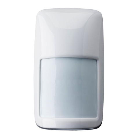
Digital Gold Series Microwave Detector
for use with Analogue 1-10V ballasts
MLS2421A
MLS2421ASM
MLS2421AF
the volt-free output. If the output prior to pressing the switch is above 90% the
output will ramp down; if below 90% it will ramp up. If the latest press and the
current press are within 5 seconds of each other it will ramp in the opposite
direction.
Commissioning
The units are supplied with the factory default settings shown below which
render commissioning unnecessary in many applications. To make use of the
programmable settings, an infrared commissioning tool is required (HP2000).
Aten-second "Walk Test" time delay is selectable to aid commissioning
Factory Default Settings
These are the settings to which the units have been programmed before they
leave the factory.
Digital Gold Series Microwave Detector for use with Analogue
1-10V Ballasts
Only suitably qualified personnel should install this equipment.
This high-performance, communicating presence detector can be used as part
of a full Ex-Or MLS Digital Managed Lighting System or as a stand-alone unit.
The detector is equipped with a regulating photocell to control analogue 1-10V
ballasts (when using its Dimming Output) and a volt-free output to fully
extinguish analogue dimmable loads or for control of non-dimmable lighting
loads. The detector incorporates Ex-Or’s OneSwitch Dimming, allowing local
manual operation of any controlled lighting load.
Location
This
it be installed on a rigid surface that will not itself be subject to movement or
vibration.
Please note that microwave detectors are not recommended for applications
where there are large surface areas of metal, e.g. metal ceiling or floor tiles, as
unpredictable sensitivity may result.
The units are graded according to four variations in operating frequency. Each
type can be identified by different colour-coding on the detector label and
carton. For reliable operation it is essential that units of the same colour code
do not occupy adjacent positions in open-plan areas or in adjoining rooms (see
below).
is an extremely sensitive movement detector; it is essential therefore that
Yellow
Blue
Red Green
Red Green
Green
Green
Blue
Red Green
Red Green
Blue
Blue
Red
Red
Blue
Yellow
Blue
Red Green
Red Green
Blue
Green
Green
Blue
Red Green
Red Green
Blue
Blue
Red
Red
Blue
Red Green Green Red Green
Blue
Red
Blue
Red Green
Blue
Green Red Green
Blue
Red
Blue
Note: Should it be necessary to order additional detectors for an existing
installation and specific colour-coded detectors are needed, please add the
following suffixes to the part number: Y = Yellow, B= Blue, G= Green, R = Red.
(There is normally no need to specify the colour codes, as orders are
dispatched with a suitable colour code mix.)
Fixing
MLS2421ASM - The housing may be secured to a hard surface or a BESA
box. The unit fits into the housing with a simple bayonet action.
MLS2421AF - Depth required behind ceiling: 62mm from front flange plus an
allowance for the minimum bend radius of the cable. Sinking box fits into a
89mm diameter hole in ceiling tile or plasterboard ceiling. To avoid damage to
ceiling tile, do not overtighten. No access above the ceiling is necessary.
Please note: Do not position this product on a pitch narrower than 5m.
Do not mount within 0.25m of a luminaire.
Electrical Connections
The detector should be connected in accordance with the diagrams opposite.
The detector's MLS connections are polarity-free, however some other MLS
products require that polarity be maintained so it is good practice to observe a
constant polarity with respect to the bus cable core colours. The MLS cable
should be mains-rated, unscreened, twisted pair of at least 1.5mm sq CSA.
For further information please refer to WiringApplication Guide AN4001.
Each luminaire to be controlled must contain an analogue regulating type
ballast with the appropriate analogue input. Ballast types must not be mixed.
The analogue input terminals on the ballasts should be connected in parallel
with each other and to the analogue 1-10 V output terminals on the rear of the
detector, observing the polarity. Also each of these analogue regulating ballast
Live inputs (maximum load 6 Amps) must be provided by the Volt-free output
(see 1st Wiring Example) from the detector.
When switching via the volt-free output multiple MLS2421A detectors may be
connected in parallel provided the controlled load does not exceed 6 Amps
(see 3rd Wiring Example).
DO NOT CONNECT DIMMING OUTPUTS TOGETHER .
OneSwitch
OneSwitch Dimming affords local control to the end-user whereby a simple,
momentary, push-to-make wallswitch can be used to raise or lower the lighting
level or toggle the output of the unit ON or OFF. A short press (less than
1 second) toggles the relay output from OFF to ON or from ON to OFF.
A long press will ramp the analogue output either up or down with no effect on
Sensitivity to Movement
While the factory settings will be correct for many applications, the sensitivity
can be adjusted if required.
ON Sensitivity (ON Range): This sets the detector’s range when the lights
are ON. (i.e. the space is Occupied) Choose setting from 1-100 where 1 is
lowest and 100 is maximum. (Note: Choose the lowest level possible to give
adequate detection.)
OFF Sensitivity (OFF Range): This sets the detector’s range when the lights
are OFF. (i.e. the space is Unoccupied/Vacant) Choose % setting from 10%
to 100% where 10% = 10% of ON Sensitivity and 100% = same as ON
Sensitivity. This is an approximation and should be tested on site during
commissioning.
Generally the OFF Sensitivity should be significantly less than the ON
Sensitivity as in the ON/Occupied state small movements of e.g. seated
persons must be detected while in the OFF/Vacant state only the gross
movements of persons entering the space need to be detected. This
differential sensitivity prevents false triggering of the Presence Detection
logic.
Like all programmable parameters, the sensitivity settings will be retained in
the event of a power failure and can be re-programmed any number of times.
Commissioning the Photocell
Commissioning the setpoints for Photocell based control requires the
HP2000 Hand-held Programmer.This tool should be used aimed squarely at
the front of the Detector/Photocell at a distance of 1m although it can work at
substantially greater distances if aimed carefully.
Regulating Only: For this mode the PCELL RLY action should be set to
“DISABLED” and the lights will be on continuously during periods of
occupancy. The Analogue 1-10V output dims the ballast(s) in the luminaires.
It always tries to maintain a programmed light level on the working plane. It
aims for the level stored in the parameter Set-point Low.
Sometimes it is convenient to limit the extent to which the presence detector
with photocell is allowed to dim the light output of the luminaire(s). This can be
done by setting the "DIMMING" parameter. This setting determines the range
over which dimming can be operated e.g. setting 80% allows the lumiaires to
be dimmed down to a minimum of 20% of its possible output as natural light
strengthens.
Parameter
Power up
Response
Off Delay
On Sensitivity
Off Sensitivity
Bus Connect
1st Zone
2nd Zone
3rd Zone
4th Zone
Corridor 1 Begin:
Corridor 2 End:
Global 1 Rx
Global 2 Rx
Manual I/P
Entry Scene
Lamp Max
Dimming
Fade to Off
When Vacant
PCell Rly
Set-Point Low
Set-Point High
Corridor 1 End:
Corridor 2 Begin:
Start Lamps
Default
Setting
ON
AUTO
20 min
80
80%
-
-
-
-
-
-
-
-
NO
NO
LOCAL
1
100%
100%
NO
NO
1023
1023
YES
MAX
Disabled
Options
ON/OFF
Auto/Semi-auto
1min-96hrs or Disabled
1-100
10-100% in 10% increments
A 1-100
A 1-100
A 1-100
Address 1-100
1-100 Building Address Span
YES/NO
YES/NO
LOCAL/SHARE
1-6
10%-100%
YES/NO
10 Exit Scenes
Disabled, Passive, Active
0-1023
0-1023
YES/NO
ddress
ddress
ddress
1-100 Building Address Span
MAX/MIN
REG 50%-100%
Options
Each of these settings
can be re-programmed,
if desired, by use of the
infrared programming
tool HP2000.
Yellow
Yellow
Yellow
Yellow
Yellow
Yellow
Yellow
Yellow
Yellow
Yellow
Yellow
Yellow
Yellow
Yellow
Yellow
Yellow
Blue
Blue
Output
1-10V MLS
BUS
MLS Connection is
Polarity-Free
+ - 1 2
MLS2421A
Using OneSwitch, MLS, Switched and
Analogue Outputs
N
E
L
Permanent
or switched
supply
VOLT-
FREE
OUTPUT
LIVE
NEUTRAL
EARTH
Analogue Ballast
(MAX 6 AMPS)
ONESWITCH
DIMMING
Analogue output
MLS Bus Connection
(Some MLS devices
require that polarity
be maintained)
Momentary
push-to-make
switch
Wiring Examples
2 x MLS2421A
In Parallel, using Switched
Output only
LOAD
(Max 6 Amps)
N
E
LPermanent
or switched
supply
VOLT-
FREE
OUTPUT
VOLT-
FREE
OUTPUT
LIVE IN LIVE IN
NEUTRAL NEUTRAL
EARTH EARTH
Any connection not shown is NO CONNECTION
ONE
SWITCH
NC NC
ONE
SWITCH
Relay outputs may be connected together in parallel to cover larger areas,
however the total load on all combined relay outputs must not exceed 6 Amps.
User Overrides
The end-user can configure a number of lighting scenes that can be recalled
using a hand-held override. With an HC5 hand-held controller lighting can be
overridden OFF or ON, or a set level can be chosen, affecting either the
controlled group or, with an MLS system, the whole zone. Regulating and
switched loads can be adjusted independently through a combination of
OneSwitch Dimming and the HC5 Hand-held Controller.
W4474D
MLS2421A
Using Switched Output and MLS
1-10V
Output
MLS
BUS
+ - 1 2
N
E
L
Permanent
or switched
supply
VOLT-
FREE
OUTPUT
LIVE
NEUTRAL
EARTH
LOAD
(MAX 6 AMPS)
ONESWITCH
DIMMING
NC
Please note that the Earth terminal
has no internal connection and is
used for termination only.
Please note that the Earth terminal
has no internal connection and is
used for termination only.
MLS Connection is
Polarity-Free
Momentary
push-to-make
switch
DO NOT CONNECT DIMMING OUTPUTS TOGETHER .
If it is desired to operate the lighting without any automatic photocell based
control over the dimming process, (e.g. only manual control of dimming, by
OneSwitch, and/or scene setting by HC5 Infrared Hand-held Controller is
required) then the default values of 1023 should be retained in the parameters
Set-point Low and Set-point High.
Programming the Regulating level: Place a light meter on the working
plane underneath the presence detector with photocell. Adjust the light output
of the luminaire up or down manually by infrared. (On the HP2000, select
“UTILITIES” from the Main Menu and then “SET LIGHT LEVEL” from the
UTILITIES Menu. The up and down Arrow keys allow adjustment of the light
level up and down whilst pointing the handset at the presence detector with
photocell.) When the light meter reads the desired level, press and hold the
central “OK” button until the lights “blink” to acknowledge that the
photocellreading has been stored in the Set-point Low parameter. This is the
control set-point for the regulating process which tries to maintain this
photocell reading at all times by dimming or brightening the lights.
Switching the Lighting Load:
In addition to dimming the lighting load via the 1-10V output, the load can also
be controlled by the relay according to natuiral light level.This form of control
is governed by the setting of the parameter PCELL RLY. There are three
options for this parameter:-
DISABLED: In his mode the photocell has no effect upon the operation of the
relay - it will switch only according to detected occupancy.
PASSIVE: In this mode the relay will be inhibited from closing if the area is
entered when the ambient light level is above Set-point Low. If during the
period of occupancy, the light level falls below Set-point Low, then the lights
will switch on. In this mode the lights will never switch off during a period of
occupancy - no matter how bright it becomes.
ACTIVE: This is the same as PASSIVE mode except that, additionally, the
lights will switch off if the light level exceeds Set-point High even if the area is
occupied. For the switch-off to occur, the light level must persist at this high
level for the full duration of what is called a "Passing Cloud Timer" (PCT). The
PCT is usually of the same duration as the Off-delay used by the Presence
Detection logic; however when an unusually long Off-delay is configured the
PCT is automatically capped at 20 minutes. If the light level falls below Set-
point Low during a period of occupancy, then the lights are switched on
immediately without any delay.
Programming the Set-points:
1)Simple PCELL RLY Switching Control:
i) If PCELL RLY-ACTIVE switching action is required it is important that the
lights are switched on at least 15 minutes before this procedure is undertaken
to allow the tubes to reach full output. For PCELL RLY-PASSIVE switching
action this is not necessary.
ii) Download the settings already established within the Detector for non-
Photocell related features to the HP2000. Edit the Photocell setting to ACTIVE
or PASSIVE as required. Upload the whole configuration to Detector.
iii)Wait until the appropriate time of day for, or use blinds to create, the natural
light level, as measured with a light meter, below which you would want the
lights to be on and above which you would not want the lights to be on.
iv) Start the internal self-programming operation by selecting UTILITIES/SET
LIGHT LEVEL on the HP2000 and pressing and holding the "OK" button. The
Detector takes a Photocell reading, adds a small margin and stores the
resulting value as Set-point High. It then switches off the controlled lights and
takes another Photocell reading which it stores as Set-point Low. The lights are
now switched on again, completing the acknowledgement "blink". The OK
button can now be released. Note that the difference between the two Set-point
values, the Switching Hysteresis, is equal to the contribution to total light made
by the controlled luminaires. This is the ideal amount of hysteresis to prevent
oscillation without compromising control accuracy.
Lights ON = Lights OFF =
Set-point High
Set-point Low
Natural
Light
Level
Duration of
PCT
Active Mode
Passive Mode
Occupancy
Area Occupied = Area Unoccupied =
2) Regulating Control overlaid by PCELL RLY Switching Control
First carry out the commissioning procedure described for Regulating Only
control (under Photocell Commissioning). When the Regulating Only
commissioning procedure has been carried out the HP2000 parameter Set-
point Low within the Detector has acquired a new, non-default value. This value
should be read in a full download from the Detector to the HP2000 and kept.
The Set-point High value should now be manually edited on the HP2000
screen to be about 25% higher in the same units, e.g. if a download from the
Detector to the HP2000 shows that 429 has been automatically stored into the
Set-point Low parameter, then the Set-point High value should be manually
edited to 535 or 536. The PCELL RLY action should be set to “ACTIVE” or
“PASSIVE”, as required, and the whole configuration then uploaded to the
Detector.
MLS Bus Connection
(Some MLS devices
require that polarity
be maintained)
Technical Data
2
MLS CABLE : 1.5mm unscreened twisted-pair (applicable when detector is used as part of a full MLS Digital Managed Lighting
System): see Application Note AN4001
MAXIMUM RECOMMENDED MOUNTING HEIGHT: 3.0m
RANGE: Approx 7m dia at 2.4m ceiling height
OFF DELAY: 1 minute - 96 hours/Disabled plus 10-second Walk-test Mode
PHOTOCELL: Passive/Active/Regulating adjustable 50-5000 lux
OPERATING VOLTAGE: 230V 50Hz (UK & Europe)
PRODUCT RATING AND RECOMMENDED CIRCUIT PROTECTION: 10 Amps
MAXIMUM RECOMMENDED LOAD (VOLT-FREE): 6 Amps
MAXIMUM RECOMMENDED LOAD (ANALOGUE 1-10V): 20 Ballasts
DIMMING OUTPUT: Analogue 1-10V
COLOUR: White
MATERIAL: Flame retardant PC/ABS
WEIGHT: 300g
IP RATING: 2X
W4474D
Ex-Or
Novar ED&S Limited
Haydock Lane, Haydock,
Merseyside WA11 9UJ
Tel: +44 (0)1942 719229
Fax: +44 (0)1942 508753
Email: technicalsales.ex-or@honeywell.com
www.ex-or.com
At the end of their useful life
the packaging and product
should be disposed of via a
suitable recycling centre.
Do not dispose of with normal
household waste.
Do not burn.
100mm
100mm
Dimensions
62mm
deep
62mm deep
behind ceiling
MLS2421AF MLS2421ASM
Flange:
15mm deep
Important Additional Notes
1. All terminals on this product are provided for final connections. It is not intended that the product be used as a junction box for looping cables.
2. Ameans for disconnection must be incorporated in the fixed wiring in accordance with the current wiring regulations.
3. Although nominally 12V, the dimming output is not SELV and therefore should be treated with the same respect as mains with regard to wiring practice. The
0V line of the dimming output is almost at Neutral potential.
4. The dimming control output should be connected only to the control input of the ballasts - never to other detectors.
5. Due to the fact that the photocell is on the ceiling looking down, it is not possible for measurements made with a lux meter on the working plane to remain
constant when daylight illuminates the ceiling and the working plane to a differing extent. Therefore, products of this type should be regarded as capable of
maintaining anAPPROXIMATE light level only.
6. This equipment switches lights no more frequently than would a responsible human occupant. However, manufacturers of some lighting types (e.g. ‘2D’
luminaires) may specify a maximum number of switching cycles in order to achieve a predicted lamp life. Please check with the manufacturer of the
luminaires to ensure that they are compatible with automatic controls in this respect.
7. The detectors are extremely sensitive to movement; they must be mounted on a solid surface which has no movement whatsoever.
8. This equipment should be used to control only those ballasts powered from the same phase as the detector.

This manual suits for next models

2

Other Honeywell Security Sensor manuals

Honeywell C7076D1027/U User manual

Honeywell

Honeywell C7076D1027/U User manual

Honeywell EC-FX-NH3 Manual

Honeywell

Honeywell EC-FX-NH3 Manual

Honeywell SiX Series User manual

Honeywell

Honeywell SiX Series User manual

Honeywell Lyric W1 User manual

Honeywell

Honeywell Lyric W1 User manual

Honeywell NOTIFIER IRX-751CTEM User manual

Honeywell

Honeywell NOTIFIER IRX-751CTEM User manual

Honeywell IQ Force Installation manual

Honeywell

Honeywell IQ Force Installation manual

Honeywell TRADELINE C554A User manual

Honeywell

Honeywell TRADELINE C554A User manual

Honeywell MILLER 1032363 User manual

Honeywell

Honeywell MILLER 1032363 User manual

Honeywell R4343E User manual

Honeywell

Honeywell R4343E User manual

Honeywell Farenhyt Series User manual

Honeywell

Honeywell Farenhyt Series User manual

Honeywell Ex-Or MR2500D Installation and operation manual

Honeywell

Honeywell Ex-Or MR2500D Installation and operation manual

Honeywell ToxiPro CO User manual

Honeywell

Honeywell ToxiPro CO User manual

Honeywell krom schroder DG Smart Manual

Honeywell

Honeywell krom schroder DG Smart Manual

Honeywell AreaRAE Plus User manual

Honeywell

Honeywell AreaRAE Plus User manual

Honeywell 997 User manual

Honeywell

Honeywell 997 User manual

Honeywell Viewguard DUAL AM FAI Instruction manual

Honeywell

Honeywell Viewguard DUAL AM FAI Instruction manual

Honeywell Ex-Or MLS Installation and operation manual

Honeywell

Honeywell Ex-Or MLS Installation and operation manual

Honeywell Purple Peeper C7012A User manual

Honeywell

Honeywell Purple Peeper C7012A User manual

Honeywell LightSpot LS1000R User manual

Honeywell

Honeywell LightSpot LS1000R User manual

Honeywell Smart Seal P3S User manual

Honeywell

Honeywell Smart Seal P3S User manual

Honeywell Sensepoint XCD User manual

Honeywell

Honeywell Sensepoint XCD User manual

Honeywell IS312B User manual

Honeywell

Honeywell IS312B User manual

Honeywell FSL100-IR3 Release Note

Honeywell

Honeywell FSL100-IR3 Release Note

Honeywell 748LC User manual

Honeywell

Honeywell 748LC User manual

Popular Security Sensor manuals by other brands

Dragino LHT65N-E5 user manual

Dragino

Dragino LHT65N-E5 user manual

IKEA VALLHORN manual

IKEA

IKEA VALLHORN manual

Dingtek DF703 datasheet

Dingtek

Dingtek DF703 datasheet

LynRus Aut-O-Loc 3 installation instructions

LynRus

LynRus Aut-O-Loc 3 installation instructions

Visonic DISCOVERY QUAD MCW installation instructions

Visonic

Visonic DISCOVERY QUAD MCW installation instructions

STI F3SJ-AM P Series user manual

STI

STI F3SJ-AM P Series user manual

GENEVO One S user manual

GENEVO

GENEVO One S user manual

Smartenit ZBMS3 quick start guide

Smartenit

Smartenit ZBMS3 quick start guide

ESA Corona CAD Operating and maintenance manual

ESA

ESA Corona CAD Operating and maintenance manual

Martec Sentinel MLXSP524WS quick start guide

Martec

Martec Sentinel MLXSP524WS quick start guide

CARLO GAVAZZI Guardian 2 Original user manual

CARLO GAVAZZI

CARLO GAVAZZI Guardian 2 Original user manual

PCE Health and Fitness PCE-LDC 8 user manual

PCE Health and Fitness

PCE Health and Fitness PCE-LDC 8 user manual

Honeywell Home 5800PIR-RES Installation and setup guide

Honeywell Home

Honeywell Home 5800PIR-RES Installation and setup guide

Fraba Vitector RAY-LG Series manual

Fraba

Fraba Vitector RAY-LG Series manual

Bosch ISC-BPR2-WP12 installation guide

Bosch

Bosch ISC-BPR2-WP12 installation guide

Bentel Security FC450IB manual

Bentel Security

Bentel Security FC450IB manual

Satel SLIM-PIR-LUNA-PET manual

Satel

Satel SLIM-PIR-LUNA-PET manual

Linxon LX218 operating manual

Linxon

Linxon LX218 operating manual

manuals.online logo
manuals.online logoBrands
  • About & Mission
  • Contact us
  • Privacy Policy
  • Terms and Conditions

Copyright 2025 Manuals.Online. All Rights Reserved.