Honeywell TELEPHONE ACCESS MODULE W8735D User manual

INSTALLATION INSTRUCTIONS
69-2027-01
W8735D Telephone Access Module
APPLICATION
The W8735D Telephone Access Module (TAM) provides
remote telephone access to the HVAC system when used with
an EnviraCOM™ enabled thermostat such as the
TH9421C1004 VisionPRO IAQ Total Home Comfort System,
and the TH5320C1002 FocusPRO and T8635L1013
Chronotherm™ thermostat. These thermostats are used with
one or more of the following controls: a W8835A EnviraZone
panel, a THM5421C1008, W8635A and B Equipment
Interface Modules, or W8703 Damper Interface Modules. See
the product data sheets for these thermostats to see with
which devices each model would be used. The W8735D also
communicates with R7184P and U oil primary controls and
L7224U Aquastat ®, remote temperature sensors as well as
any other EnviraCOM enabled controls to communicate
current status and alert information.
The user can dial into the TAM and hear local temperatures
and system settings. The user defines the temperature and
humidityalimits and their alert priorities to best meet their
monitoring needs.
The W8735D provides remote telephone access for up to four
EnviraCOM independent channels. See Table 1 on page 2 for
the channels and zones available with each model. The
W8735D can be programmed to alert the homeowner and/or
an optional service contractor of abnormal conditions or
lockouts. Up to three different dial-out numbers (main,
backup, and contractor) can be entered in order to insure
alerts are well communicated.
Auxiliary input contacts allow integration of dry contact 24 Vac/
Vdc sensors to interface with the W8735D. In addition to
EnviraCOM thermostats, temperature alerts can be generated
using standard 24 VAC thermostats when interfacing with the
Auxiliary inputs. Auxiliary output contacts allow local
annunciation of alert conditions. Battery back-up enables the
W8735D to let the homeowner know the power is out at the
monitored location (optional 9V battery not included).
The W8735D can share a telephone line with most answering
machines and voice mail systems. The W8735D can be
prompted to pick up a call to gain access to the HVAC system
before the answering machine or voice mail are enabled.
Additionally, he W8735D is equipped with an emergency
telephone line disconnect feature activated when another
receiver in the premise is picked up while the W8735D is
connected. Full access to the W8735D is given when the
complete pass code is entered when prompted. Limited
access is given to contractors when the last five digits of the
programmed contractor telephone number is entered as the
pass code. Contractor access is limited to the W8735D Alert
History.
WARNING
Not a life safety or monitoring device.
The W8735D is not designed for use as a life safety
monitoring device to detect and generate alarms
based on the presence of toxic gases, smoke or fire
within residential homes or commercial buildings. The
incorporation of CO, CO2, smoke, fire, radon or other
life safety sensors for monitoring by the W8735D is not
recommended, nor should the W8735D be used in lieu
of fire alarm, smoke detector, gas detector or other life
safety monitoring systems.
aHumidity is available only when used with the TH9421C1004
VisionPRO IAQ Total Home Comfort System.

W8735D TELEPHONE ACCESS MODULE
69-2027—01 2
SPECIFICATIONS
Power Source: 12 Vdc (±5%) 1.0A
9 Vdc battery backup
Power connection via 12 Vdc plug
Temperature Ratings:
Storage Range:
-30° F (-34° C) to 150° F (65° C)
Operating Temperature Range:
32°F (0° C) to 120°F (49° C)
Humidity Rating: 5%-95% RH non-condensing
Finish: White ABS
Dimensions: See Fig. 2 on page 4
Mounting: No. 6 screws and wall anchors supplied in bag
assembly
Wiring: AWG 18 or 20 wire
Channel Specification:
1/D - Data line
2/R - 24 Vac Hot
3/B - 24 Vac Common
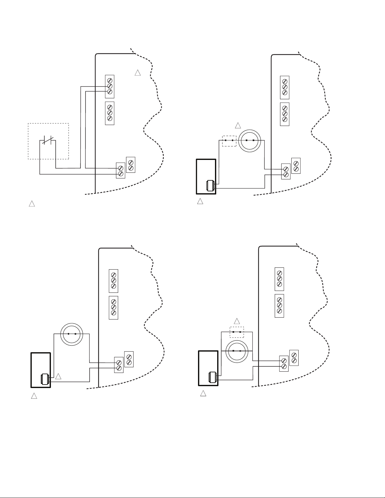
Auxiliary Input: N.C. sensor contact, 24 Vac/Vdc, polarity
insensitive
— Accepts up to 30 Vac or Vdc presenting no more than
a 10 mA load.
— A transition to less than 18 Vac/Vdc signifies an alert
condition.
Auxiliary Output: N.O. dry contact, 24 Vac/Vdc
— Supports a load current up to 1 A
— Contact closes during an unacknowledged alert condi-
tion
Operating Limits:
Indoor Temperature:
Low Limit default: 50° F (10° C)
High Limit default: 90° F (32° C)
Range: 40° F (4° C) to 99° F (37° C)
Outdoor Temperature:
Low Limit default: 40° F (4° C)
High Limit: default 105° F (40° C)
Range: -40° F (-40° C) to 150° F (65° C)
Humidity:
Low Limit default: 25%
High Limit default: 70%
Range: 5% to 95%
Approvals:
Federal Communications Commission: Part 15
Federal Communications Commission: Part 68
Registration Number. US: HCPAL01ATAM
Recommended Accessories:
• TH9421C1004 VisionPRO IAQ Total Home Comfort
System
• TH5320C1002 FocusPRO EnviraCOM™ Thermostat
• W8835A EnviraZone panel for zoning
• W8703A Damper Interface Module (for zoning)
• 50022037-001/U EnviraCOM Outdoor Temperature Sensor
(when a TH9421C1004 VisionPRO IAQ along with a
W8835 EnviraZone panel is used)
• C7089U1006 Outdoor Temperature Sensor (when a
YTH9421C1002 Total Home Comfort System is used)
• C7089B1000 Outdoor Temperature Sensor (when a
T8635L thermostat is used)
• 9-volt alkaline battery (for power outage detection)
• R8228D1018 DPST N.O. General Purpose Relay
• R8228B1012 SPDT General Purpose Relay
• AT120A1004 General Purpose 20VA Transformer
Battery Indication
A two-colored LED indicator is located in the lower right
corner of the W8735D Telephone Access Module that
indicates device power and battery health.
The LED has the following states:
•Steady Green: Input powered, battery health is good
•Flashing Green: Input powered, battery health is low
•Flashing Alternate Green/Red: Input powered, battery is
dead or missing
•Off: W8735D is not powered
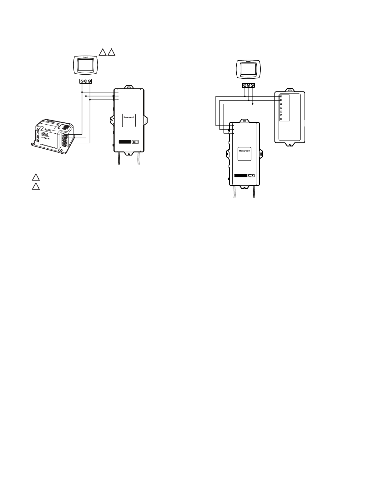
Table 1. W8735D Model Descriptions.
Model Application Connections Communicates with:
W8735D1009 Remote dial-in/dial-out using a
conventional telephone line.
Two independent EnviraCOM channels
each capable of communicating with up
to nine zones (up to 18 zones total).
•1/D, 2/R, 3/B (terminal
connections per channel; two
channels total)
•Aux In 1, Aux In 2
•Aux Out 1, Aux Out 2
•Telephone, Power, and Battery
•VisionPRO IAQ YTH9421C1002 or
TH9421C1004 with THM5421C1008
Equipment Interface Module or
W8835A EnviraZone panel for
zoning
•Compatible with T8635L using
W8635A or B
•W8703 Equipment and Damper
Interface Modules or W8835A
EnviraZone panel for zoning
•R7184 Oil Primary
•L7224 Aquastat®
W8735D1017 Remote dial-in/dial-out using a
conventional telephone line.
Four independent EnviraCOM channels
each capable of communicating with up
to nine zones (up to 36 zones total).
•1/D, 2/R, 3/B (terminal
connections per channel; four
channels total)
•Aux In 1, Aux In 2
•Aux Out 1, Aux Out 2
•Telephone, Power, and Battery

W8735D TELEPHONE ACCESS MODULE
369-2027—01
Alert Messages
Alert messages are dialed-out to the configured phone
numbers for the following conditions (factory priority/default
settings shown in parentheses):
Power Outage (high priority) Power was out at this location
for more than one hour.
Power Restore Power has been restored at this location.
Low Battery (low priority) Replace battery.
Auxiliary Input (high priority) Optional auxiliary input sensor
has tripped.
Pass Code Change (high priority) The pass code has been
altered.
Low Temp Limit (high priority, default 50° F (10° C) The
room temperature dropped below the low limit setting.
High Temp Limit (high priority, default 90° F (32° C) The
room temperature exceeded the high limit setting.
Outdoor Low Temp Limit (high priority, default 40° F
(4° C) The outdoor temperature dropped below the low limit
setting.
Outdoor High Temp Limit (high priority, default 105° F
(40° C) The outdoor temperature exceeded the high limit
setting.
Air Filter (low priority) Change air/duct filter.
Humidity Low Limit (high priority, default 25%) The indoor
humidity dropped below the low limit setting.
Humidity High Limit (high priority, default 70%) The indoor
humidity exceeded the high limit setting.
System Failure (high priority) HVAC system/component
alert.
INSTALLATION
When Installing this Product…
1. Read these instructions carefully. Failure to follow these
instructions can damage the product or cause a hazard-
ous condition.
2. Check the ratings given in the instructions and on the
product to make sure the product is suitable for your
application.
3. Installer must be a trained, experienced service techni-
cian.
4. After completing installation, use these instructions to
check out the product operation.
CAUTION
Electrical Shock Hazard.
Can injury and equipment damage.
Disconnect power before beginning installation.
Location
Locate the W8735D near the HVAC equipment and where
access to the telephone line is available. See Fig 1.
Fig. 1. Locating the W8735D in the Equipment Room.
CAUTION
Equipment Mounting Damage Hazard.
Can damage W8735D when mounted inside HVAC
equipment.
Mount W8735D outside of any HVAC equipment
where access to telephone line is available.
M23746
WATER HEATER
W8735D
FURNACE OR BOILER

W8735D TELEPHONE ACCESS MODULE
69-2027—01 4
W8735D Base Installation
Mount the W8735D in the equipment room near the indoor
HVAC equipment. Position the W8735D horizontally so that all
wiring connections face toward the floor or vertically so that
the power and telephone plugs face the floor. See Fig. 3.
IMPORTANT
Turn OFF all power to heating and cooling equip-
ment.
1. Position the W8735D on the wall outside of the indoor
HVAC equipment. Level the module for appearances
only; the module functions properly even when not
level.
2. Use a pencil to mark the mounting holes to be used.
The W8735D has two external mounting holes and two
external flanges to accommodate a vertical or horizontal
installation position. See Fig. 3.
3. Use a minimum of one hole and one flange to mount the
W8735D.
4. Remove the W8735D from the wall and drill a minimum
of two 3/16-in. holes in the wall (if drywall) as marked.
For firmer material such as plaster, drill a minimum of
two 7/32-in. holes. When mounting on the indoor HVAC
equipment, drill pilot holes where marked.
5. When mounting on the wall, gently tap anchors (pro-
vided) into the drilled holes until flush with the wall.
6. Position the W8735D over the drilled holes. Insert the
mounting screws (provided) in the holes and tighten.
7. A Honeywell label is provided in a bag with the
W8735D. Remove the adhesive backing from the label
and place it on the unit in its proper orientation as
shown in Fig. 3.
Fig. 2. W8735D Dimensions in inches (mm).
Fig. 3. W8735D Mounting Orientations.
Wiring
CAUTION
Voltage Hazard.
Can cause electrical shock or equipment damage
Disconnect power before beginning installation.
IMPORTANT
All wiring must comply with local electrical codes and
ordinances.
IMPORTANT
Use 18 to 20 gauge color-coded cable for proper wir-
ing. Shielded cable is typically not required.
Keep this wiring at least one foot away from large
inductive loads such as electronic air cleaners,
motors, line starters, lighting ballasts, and large dis-
tribution panels. Failure to follow these wiring prac-
tices may introduce electrical interference (noise)
which can cause erratic system operation. All
unused thermostat wire is to be grounded at control-
ler end only. The communication cable must not
exceed 1,000 feet (305 M).
10
(254)
Telephone Access
Module
EnviraCOM™
Enabled
12V DC
5 (127)
2
(51)
M23748
VERTICAL MOUNTING (PORTS FACING LEFT)
HORIZONTAL MOUNTING (PORTS FACING DOWN)
MOUNTING
HOLE (x2)
MOUNTING
FLANGE (x2)
M23747

W8735D TELEPHONE ACCESS MODULE
569-2027—01
General Wiring Directions
Refer to Fig. 4 and Table 2 for the location and function of
each terminal.
IMPORTANT
Wire the W8735D without the 12 Vdc power con-
nected.
1. Remove power from all devices to be connected to the
W8735D (Channels and Auxiliary Input and Output).
2. Remove the cover from the W8735D by gently pulling
the cover plate outward to disengage the friction
latches, which are on the side opposite of the wiring
connections (see Fig. 18 on page 11).
3. Identify the terminal block to be connected and loosen
the terminal screws using a 3.5 mm slotted screw driver.
a. See “Wiring the Communication Bus Channels” on
page 6.
b. See “Wiring the Auxiliary Input/Output Terminals” on
page 9.
4. Insert wire end through the rubber grommet, which is
supplied in a bag assembly.
5. Place the cable inside the terminal and securely tighten
each terminal screw.
6. As needed, adjust the position of the grommet and
press it into place in the fitting provided on the base.
See Fig. 4.
7. Replace the cover.
8. Bundle the wires and tie-off using the two wire tie-offs
molded into the base. See Fig. 4.
Fig. 4. Wiring Connections (4-channel).
RUBBER
GROMMET (X4)
CHANNEL 1
CHANNEL 2
CHANNEL 3
CHANNEL 4
AUXILIARY
INPUT
AUXILIARY
OUTPUT
POWER
TELEPHONE
SIDE VIEW SHOWING CHANNEL AND AUXILIARY PORTS
RUBBER
GROMMET (X4)
M23749
WIRE
TERMINAL BLOCK
3.5 MM
SLOTTED
SCREW DRIVER
DOUBLE RUBBER GROMMET
DOUBLE RUBBER
GROMMET
RISER
BOARD FOR
CHANNELS
1 AND 2
RISER
BOARD FOR
CHANNELS
3 AND 4
MAIN CIRCUIT
BOARD
MAIN CIRCUIT
BOARD
Table 2. Terminal Designations.
W8735D
Terminal
Designation Function
Channel 1
1/D (channel 1) To EnviraCOM channel 1 network; DATA
2/R (channel 1) To EnviraCOM channel 1 network; 24 Vac Hot
3/B (channel 1) To EnviraCOM channel 1 network; 24 Vac Common
Channel 2
1/D (channel 2) To EnviraCOM channel 2 network; DATA
2/R (channel 2) To EnviraCOM channel 2 network; Vac Hot
3/B (channel 2) To EnviraCOM channel 2 network; 24 Vac Common
Auxiliary
Auxiliary Output (DO) Connect to N.O. contact; alarm input
Auxiliary Input (DI) Connect to N.C. sensor contact; 24 Vac/Vdc
Channel 3 (Model 1017 only)
1/D (channel 3) To EnviraCOM channel 3 network; DATA
2/R (channel 3) To EnviraCOM channel 3 network; Vac Hot
3/B (channel 3) To EnviraCOM channel 3 network; 24 Vac Common
Channel 4 (Model 1017 only)
1/D (channel 4) To EnviraCOM channel 4 network; DATA
2/R (channel 4) To EnviraCOM channel 4 network; Vac Hot
3/B (channel 4) To EnviraCOM channel 4 network; 24 Vac Common
Table 2. Terminal Designations. (Continued)
W8735D
Terminal
Designation Function

W8735D TELEPHONE ACCESS MODULE
69-2027—01 6
Wiring the Communication Bus Channels
Connect terminals 1/D, 2/R, 3/B from the desired channel
(starting with the channel 1 bus) of the W8735D to the other
network devices using a 3.5 mm slotted screw driver. Fig. 5
describes the terminal connections for each channel.
• Terminal 1/D is communications
• Terminal 2/R is 24 Vac Hot
• Terminal 3/B is 24 Vac Common
Fig. 5. Communication Bus Terminals (4-channel).
Wiring Application Examples
See Fig. 6 – Fig. 9 for typical W8735D wiring applications.
Fig. 6. W8735D with Network Zoning (W8635A and W8703A).
CHANNEL TERMINAL
M23750
1/D
2/R
3/B
L1
(HOT)
L2
SYSTEM
TRANSFORMER
COOL 1
RELAY
HEAT 2
RELAY
FAN
RELAY
OT
OT 2
1 3
M23868
C7089B
OUTDOOR
TEMPERATURE
SENSOR
T8635L
HEAT 1
RELAY
W8635A
C
R
RH
RC
1
2
3
Y2
W2
Y1
G
W1
COOL 2
RELAY
W8703A
L1
(HOT)
L2
EXTERNAL
40 VA
TRANSFORMER
OT
OT 2
1 3
T8635L
OT
OT 2
1 3
T8635L
ZONE AZONE B
ZONE C
CLOSE
OPEN
OPEN
CLOSE
OPEN
CLOSE
COM
TR1
TR2
2
3
1
54 6 Z
21 3 X
MODEL AOBD
ZONE DAMPER
POWER-CLOSED/
SPRING-OPEN
(MODEL ZD)
POWER-CLOSED/
SPRING-OPEN
(MODEL ARD)
1/D
W8735D
TELEPHONE
ACCESS MODULE
TelephoneAccess
Module
EnviraCOM™
Enabled
2/R
3/B

W8735D TELEPHONE ACCESS MODULE
769-2027—01
Fig. 7. W8735D with EnviraZone Panel (W8835).
1/D
123 123
L
C
RH
RC
W1/E
W2
W3/AUX
Y1
Y2
G
O/B
HUM
HUM
DEHUM
DEHUM
VENT
VENT
R
C
T1
T2
ZONE1
M6 M4 M1
ZONE2
M6 M4 M1
ZONE3
M6 M4 M1 1 2 3 1 2 3 1 2 3 1 2 3
DAMPERS ENVIRACOM BUS
DAMPER
XFRM
ENVIRACOM
XFRM
REMOVE JUMPERS IF
T1 AND T2 ARE USED
HEAT COOL ZONE 1COMEM HEATFANPURGE ZONE 3ZONE 2
W8835A
DIP SWITCH SETTINGS
1 SEE TABLEONOFF
2 SEE TABLE1 0
3 ENVIRACOM FURN NO YES
4 PURGE TIME 2 MIN3.5MIN
5 PURGE FANHVACPANEL
6 PURGE DAMPERNO CHG OPEN
7 # COMP STAGES 1 2
8 HEAT FANHVACPANEL
9 HP CHANGEOVERO B
10 UNUSED
O
N
1 2 3 4 5 6 7 8 9 10
#1 # 2 CONV HT STG
1 1 1
1 0 2
0 1 3
0 0 HP
24 VOLT/40 VA
TRANSFORMER
R
C
L1
L2
R
W1
W2
Y1
Y2
G
C
DOTTED LINES FOR 2-
STAGE APPLICATIONS
SINGLE TRANSFORMER
HEATING/COOLING SYSTEMS
REQUIRE A JUMPER TO BE
INSTALLED CONNECTING RH
AND RC (FACTORY INSTALLED).
123
EARD-6
M23865
POWER-CLOSED/
SPRING-OPEN
ZD DAMPER
POWER-CLOSED/
SPRING-OPEN
ZD DAMPER
POWER-CLOSED/
SPRING-OPEN
ARD DAMPER VISIONPRO IAQ/FocusPRO EnviraCOM™ THERMOSTATS
W8735D
TELEPHONE
ACCESS MODULE
LED STATES:
Heat LED Heating Mode
Cool LED Cooling Mode
Purge LED Purge Mode
Fan LED Fan Mode
Em Heat LED Em Heat Mode
COMM LED Communications
ZONE LEDS:
On Damper open or opening
Off Damper closed or closing
MOMENTARY PUSH BUTTONS
Boot Clears Microprocessor
Purge Override Bypass Purge Mode
Discovery Initiates Discovery Mode
Telephone Access
Module
EnviraCOM™
Enabled
2/R
3/B
TELEPHONE POWER
1 IF ALL FOUR EnviraCOM™ TERMINAL BLOCKS ARE OCCUPIED, YOU MAY SIMPLY CONNECT TO 1, 2 AND 3 ANYWHERE ON THE BUS.
1

W8735D TELEPHONE ACCESS MODULE
69-2027—01 8
Fig. 8. W8735D with Oil Primary (R7184 P and U).
Fig. 9. W8735D with VisionPRO IAQ and Equipment
Interface Module (TH9421C1004/THM5421C1008).
1/D
1
2 3
M23866A
W8735D TELEPHONE
ACCESS MODULE
VISIONPRO IAQ
Telephone Access
Module
EnviraCOM™
Enabled
2/R
3/B
TELEPHONE POWER
1
2
3
R7184U OIL
PRIMARY CONTROL
1THERMOSTAT OPTIONAL.
THE FOCUSPRO ENVIRACOM THERMOSTAT CAN NOT BE USED IN
CONJUNCTION WITH THE R7184 AND W8735D.
12
2
1 2 3
M23867
THM5421C1008
EQUIPMENT
INTERFACE MODULE
VISIONPRO IAQ/FocusPRO
EnviraCOM™ THERMOSTAT
1
2
1/D
W8735D TELEPHONE
ACCESS MODULE
Telephone Access
Module
EnviraCOM™
Enabled
2/R
3/B
TELEPHONE POWER
3
C
R
RC
RH

W8735D TELEPHONE ACCESS MODULE
969-2027—01
Wiring the Auxiliary Input/Output Terminals
The optional Auxiliary contacts are available to integrate
non-EnviraCOM sensors and switches to the W8735D and to
allow the W8735D to interface with non-EnviraCOM
monitoring devices in case an alert condition is detected.
See Fig. 10 for AUX-IN and AUX-OUT wiring connections.
AUXILIARY INPUT (AUX-IN)
Generic devices such as flood sensors, temperature
controllers (for attic or outdoor temperature sensing) and
basic 24 Vac/Vdc thermostats can be connected to the
Auxiliary Input contacts to integrate non-EnviraCOM devices
or zones to the alerting functionality of the W8735D.
The auxiliary input port is labeled DI on the side of the case.
Power from the auxiliary input (AUX-IN) may be drawn from
an active communication channel or a power supply must be
available if no communications channel is used. See Fig. 11
and Fig. 12 on page 10.
Connect the AUX-IN terminal to an optional normally closed
(N.C.) sensor contact that fulfills the desired function.
The auxiliary input accepts dry contacts or a voltage input. For
voltage input, an open contact (0 volts) issues an alert, while a
closed contact represents a normal condition (greater than 18
volts threshold). The auxiliary input accepts up to 30 Vac or
Vdc presenting no more than a 10 mA load.
AUXILIARY OUTPUT (AUX-OUT)
The Auxiliary Output closes in the event an alert condition is
detected from the W8735D or from the Auxiliary input. The
output remains closed until the user acknowledges the alert
condition even though the condition itself may have been
cleared beforehand. Use the Auxiliary Output terminal to
interface with a lamp or buzzer to locally indicate an alert
condition (see Fig. 17 on page 11) or connect to a residential
security panel in order to integrate the HVAC alerts to the
home security system (see Fig. 16 on page 11).
The auxiliary output is a normally open, dry contact that
supports a load current up to 1 A. A closed output indicates an
alert condition.
The auxiliary output port is labeled DO on the side of the case.
NOTE: The auxiliary output is “made” on all alert conditions
and is deactivated upon alert acknowledgement.
IMPORTANT:
Make sure the current draw through the Auxiliary
Output terminals does not exceed specifications.
Use relays or contactors to integrate to line voltage
devices.
IMPORTANT:
If only standard thermostats or sensors are used (no
EnviraCOM bus activity on any channel) to enunciate
temperature alerts or other abnormal conditions, be
sure to select “No Priority” for “System Alert Priority”
when setting limit priorities. Failure to do this will
result in nuisance “System Alerts”. See “1. Setting
Alert Priorities” on page 16.
Fig. 10. AUX-IN and AUX-OUT Terminals (located on the
main circuit board).
Auxiliary Input and Output Applications
AUXILIARY INPUT (AUX-IN) TERMINAL:
• Connect the auxiliary input (AUX-IN) terminals to a
normally closed dry contact sensor, drawing power from an
active EnviraCOM channel or external transformer. See
Fig. 11 on page 10.
• Connect the auxiliary input (AUX-IN) terminals to a
normally closed contact sensor, drawing 24 V power from
an external power supply. See Fig. 12 on page 10.
• For multiple sensors, connect in series to annunciate any
condition on the AUX-IN loop. See Fig. 13 on page 10.
• For multiple sensors, connect in parallel to annunciate an
“AND” condition on the AUX-IN loop. See Fig. 14 on
page 10.
• Connect a 24 Vac/dc sensor. See Fig. 15 on page 11.
AUXILIARY OUTPUT (AUX-OUT) TERMINAL:
• Connect the N.O. auxiliary output terminals to an optional
home alarm system or other local alert enunciation device.
See Fig. 16 on page 11.
• Use a 24 Vac relay if the enunciating device operates at
line voltage. See Fig. 17 on page 11.
M23751
AUXILIARY TERMINALS
AUX-IN AUX-OUT

W8735D TELEPHONE ACCESS MODULE
69-2027—01 10
Fig. 11. Wiring Normally Closed Contact Sensor to the
AUX-IN Terminal Block (Channel Powered).
Fig. 12. Wiring Normally Closed Contact Sensor to the
AUX-IN Terminal Block (External Power Supply).
Fig. 13. Wiring the AUX-IN Terminal Block with Devices in
Series (External Power Supply).
Fig. 14. Wiring the AUX-IN Terminal Block with Devices in
Parallel (External Power Supply).
POWER FROM THE AUXILIARY INPUT MAY BE DRAWN FROM AN ACTIVE
COMMUNICATION CHANNEL AS SHOWN (2/R AND 3/B).
1
CHANNEL 1
1/D
2/R
3/B
CHANNEL 2
OUTPUT
INPUT
AUXILIARY
AUXILIARY SENSOR
(DRY CONTACTS)
1
M23752
1/D
2/R
3/B
CHANNEL 1
CHANNEL 2
OUTPUT
INPUT
AUXILIARY
POWER FROM THE AUXILIARY INPUT SUPPLIED BY TRANSFORMER.
1
1
M23753
1/D
2/R
3/B
1/D
2/R
3/B
N.C.
COMBINATION OF DEVICES CONNECTED IN SERIES TO ANNUNCIATE
ON ANY EVENT ON THE AUX-IN LOOP.
1
CHANNEL 1
CHANNEL 2
OUTPUT
INPUT
AUXILIARY
1
M23754
1/D
2/R
3/B
1/D
2/R
3/B
N.C. N.C.
COMBINATION OF DEVICES CONNECTED IN PARALLEL TO
ANNUNCIATE ON AN “AND” EVENT ON THE AUX-IN LOOP.
1
CHANNEL 1
CHANNEL 2
OUTPUT
INPUT
AUXILIARY
1
1/D
2/R
3/B
1/D
2/R
3/B
M23755
N.C.
N.C.

W8735D TELEPHONE ACCESS MODULE
11 69-2027—01
Fig. 15. Wiring the AUX-IN Terminal Block to a
24 Vac/dc Sensor.
Fig. 16. Wiring the AUX-OUT Terminal Block to a Home
Security Panel.
NOTE: For the wiring in Fig. 16, be sure to check the exact
connections with the Home Security Panel Installa-
tion Instructions-Auxiliary Devices.
Fig. 17. Wiring the AUX-OUT Terminal Block to Line
Voltage Annunciating Device (Buzzer).
Replacing the Top Cover
Reinstall the cover on the W8735D as described below:
1. Align the four latches on the cover with the receptacles
on the base.
NOTE: Cover goes on only one way. The cut-out in the cover
must align with the battery cover latch on the base.
2. Gently press the cover plate into position until all four
latches engage. See Fig. 18.
Fig. 18. Replacing the Top Cover.
CHANNEL 1
CHANNEL 2
OUTPUT
INPUT
AUXILIARY
24 VAC/VDC
SENSOR
1/D
2/R
3/B
1/D
2/R
3/B
M23756
HOME SECURITY
PANEL
AUXILIARY
CHANNEL 1
CHANNEL 2
OUTPUT
INPUT
AUXILIARY
M23757
1/D
2/R
3/B
1/D
2/R
3/B
L1 L2
(OPTIONAL 24 VAC
TRANSFORMER)
CHANNEL 1
CHANNEL 2
OUTPUT
INPUT
AUXILIARY
L1
L2
N.O. 24 VAC
RELAY
24 VAC
TRANSFORMER
BUZZER
1/D
2/R
3/B
1/D
2/R
3/B
M23758
M23759
LATCH (x4)
CUT-OUT FOR
BATTERY
COVER LATCH
BATTERY COVER

W8735D TELEPHONE ACCESS MODULE
69-2027—01 12
Battery Installation
NOTE: The use of the 9 Vdc battery is optional. However,
when the battery is installed, the power outage alert
option is available.
1. Press the latch on the top of the battery cover and pull it
down and away. See Fig. 19.
2. Connect 9 Vdc battery (not included) to the connector
leads.
3. Insert the battery in the battery compartment.
4. Insert the bottom tabs of the battery cover into the slots
on the case, then swing the battery cover up and in until
the top latch engages.
Fig. 19. Battery Installation.
Connecting Power
Connect the 12 Vdc power to the W8735D power receptacle.
Fig. 20. Power Connection.
Connecting the Telephone Line
Connect the telephone line from an available telephone jack in
the equipment room to the telephone jack (RJ-11) on the
W8735D. Verify that service to the existing telephones is
available and all telephones are operational.
IMPORTANT:
Always use a DSL line filter if a DSL modem is
installed on the same telephone line as the W8735D.
Fig. 21. Telephone Connection.
The W8735D is equipped with an emergency telephone line
disconnect feature activated when another receiver in the
premise is picked up while the W8735D is connected. After
the W8735D installation is complete, be sure to verify that the
emergency telephone line disconnect is operating correctly.
1. Call the W8735D using an outside line (installers use a
cellular phone).
2. While connected to the W8735D, pick up a house tele-
phone receiver and try to acquire a dial tone by pressing
the flash key. If you hear the W8735D hang up a few
seconds later the W8735D is operating correctly, other-
wise check the phone lines and replace the device.
IMPORTANT
Do not leave the installation until the emergency tele-
phone line disconnect is operating correctly.
BATTERY COVER
BATTERY INSTALLED
9V BATTERY LEADS
BATTERY
COVER LATCH
M23760
12 VDC POWER M23761
RJ-11 PHONE JACK
M23762

W8735D TELEPHONE ACCESS MODULE
13 69-2027—01
INSTALLER SETUP
IMPORTANT
Make sure the installation of all other HVAC system
equipment is complete and turn the HVAC system
power on.
NOTE: The W8735D may not answer within the first 90 sec-
onds after applying power. This time period is used
to identify all the controls present on the bus. The
W8735D does not answer or dial-out if power is dis-
connected at the wall transformer.
IMPORTANT:
When interfacing with the W8735D, make sure to
always press firmly and fully on the telephone key.
Fast or light key presses can result in missed inputs.
IMPORTANT:
When dialing into the W8735D from a cellular tele-
phone, make sure reception is good. Faulty recep-
tion can result in missed key pad entries and
eventual time-outs and hang ups.
Initial Setting of the Pass Code
The W8735D is designed to automatically keep the pass code
in memory once set.
IMPORTANT
Do not change the pass code without the home-
owner present and aware of the new four-digit pass
code.
When connecting to the W8735D for the first time or if the
pass code has not been previously changed from the factory
setting (1, 2, 3, 4), the W8735D will direct the caller to the
pass code menu in order to change the pass code. Follow the
menu instructions:
1. Call into the W8735D using an outside line (typically an
installer would use a cellular telephone).
2. Once connected, use the telephone keypad to enter the
default four-digit pass code of 1 2 3 4 followed by the #
key on the telephone.
3. Use the telephone keypad to enter a new four-digit pass
code followed by the # key.
4. Use the telephone keypad to re-enter your new four-
digit pass code followed by the # key.
5. Write the pass code on the W8735D inside cover for
future reference in case the pass code is forgotten.
6. Once this step is complete, press the * key to return to
the Main menu.
7. Continue with the next section, “Initial Setting of the Cal-
endar and Time”.
IMPORTANT
Do not leave the pass code unchanged from the fac-
tory default setting of 1-2-3-4. Resetting the pass
code to the factory default setting will prompt the
TAM to always ask you to reset the pass code on
every connection.
Initial Setting of the Calendar and Time
NOTE: When powering up the W8735D, it is required that
the calendar date and time be setup if no EnviraCOM
thermostat with date and time functions is connected
on the bus.
NOTE: The W8735D is designed to automatically keep the
current time and day in memory once the calendar is
set.
1. From the Main menu, press 2 on the telephone keypad
and follow the voice prompts.
2. Use the telephone keypad to set the current time [in the
HHMM format] followed by the # key.
3. Press:
• 1 for AM
• 2 for PM
4. Use the telephone keypad to set the Month, Day, and
Year [in the MMDDYYYY format] followed by the # key.
5. After hearing the entered date and time, press # to exit
the Time & Date Menu if entry is correct, otherwise
press 0 to reenter correct date and time (see step 2 in
this section).
NOTE: To return to the Main menu, press the * key at any
time.
To exit the Main menu, press the # key.
OPERATION
Main Menu
Use the W8735D Main menu voice prompts to listen to the
thermostat settings and change thermostat settings, time and
date, pass code, alerts, call and ring options, limit settings,
and zone naming. See Table 3 on page 14 for the complete
W8735D voice menu tree.
• When the W8735D answers the call, the voice prompt
asks for a pass code:
“Welcome to the telephone access center. Please enter
your pass code followed by the # key.”
You have two ways to respond to this voice prompt:
1. Gain full access
• Enter the four-digit pass code followed by the # key
to access the complete menu. See “Pass Code
Menu” on page 15.
Once the pass code is entered, the W8735D
announces any unacknowledged alerts, the date,
time, relative humidity, and lists the Main menu
selections.
2. Listen to Alert History
• If the contractor telephone number has been
previously set up (as described in the “Call and
Ring Menu” section beginning on page 17), you
can enter the last five digits of the contractor
telephone number followed by the # key to access
the Alert History. Once the five digits are entered,
the W8735D announces the Alert History.
• Enter the Main menu selection number.

W8735D TELEPHONE ACCESS MODULE
69-2027—01 14
To return to the Main menu, press the * key at any time.
To exit the Main menu, press the # key.
NOTE: The W8735D has an eight second time-out if no
input is received. After eight seconds, the W8735D
asks “Are you still there?”, and repeats the last
prompt. After an additional eight seconds of no
activity, the W8735D hangs up.
IMPORTANT
Review your settings to confirm that they are correct
for your application.
Table 3. W8735D Voice Menu Tree.
Main Menu
Selection
(Key-Press) Main Menu Description
Sub Menu
Selection
(Key-Press) Sub Menu Description and Selections
1 Thermostat 1 Single thermostat settings 1 Change system setting
2Scroll to next zone a
aThis selection is active only if more than one thermostat is sensed on the communications bus channel(s).
3Scroll to previous zone a
4 Change heat set point
5 Change cool set point
2Global thermostat settings a
FOLLOW VOICE PROMPTS
3 Current outdoor temperature
4 Current humidity level
5 Scale settings (ºF or ºC)
2 Time and Date FOLLOW VOICE PROMPTS
3 Pass Code FOLLOW VOICE PROMPTS
4 Alert 1 Set alert priority
FOLLOW VOICE PROMPTS
2 Set low priority dial-out time
3 Retrieve alert history
5 Call and Ring 1 Set number of rings
FOLLOW VOICE PROMPTS
2 Set home telephone number
3 Set main telephone number
4 Set backup telephone number
5 Set contractor telephone number
6 Set dial-out sequence
6 Limit 1 Indoor low temperature limit
FOLLOW VOICE PROMPTS
2 Indoor high temperature limit
3 Outdoor low temperature limit
4 Outdoor high temperature limit
5 Low humidity level
6 High humidity level
7 Factory default limits
7 Zone 1 Assign zone names
FOLLOW VOICE PROMPTS
2 Erase all zone names
3 Set zone announcement options
9 Repeat FOLLOW VOICE PROMPTS
#Exit

W8735D TELEPHONE ACCESS MODULE
15 69-2027—01
Thermostat Menu
The Thermostat menu allows you to check a particular zone’s
settings, change a particular zone’s settings or, through the
Global Thermostat Settings option, set all the connected
thermostats’ settings at once. You can also check the outdoor
temperature (optional), humidity level (optional), and select
the units between degrees Fahrenheit (ºF) or Celsius (ºC).
From the Main menu, press 1 on the telephone keypad
and follow the voice prompts.
See Table 4.
To return to the Main menu, press the * key at any time.
Time and Date Menu
The Time and Date menu allows you to set the current time
and date for the system (for the W8735D and all connected
thermostats).
Enter the time in HHMM format (based on a 12 hour clock)
and the date in the MMDDYYYY format. If a thermostat with a
calendar feature is present on the communications bus (such
as a YTH9421C1002), its time and date will be automatically
loaded to the W8735D. The time and date on the
thermostat(s) automatically adjust when a new time and date
is entered on the W8735D.
From the Main menu, press 2 on the telephone keypad
and follow the voice prompts. See Table 3 on page 14.
To return to the Main menu, press the * key at any time.
IMPORTANT
Enter the time in HHMM format and the date in
MMDDYYYY format.
Time and Date Examples:
• Keying 0 2 5 1 # on the telephone keypad sets the time to
2:51. The W8735D then prompts you to select the correct
time period; 1 for AM or 2 for PM.
• Keying 0 9 2 0 2 0 0 6 # on the telephone key pad sets the
date to September 20, 2006.
Pass Code Menu
The W8735D limits remote access to the HVAC equipment by
implementing a pass code. The pass code must be reset from
the default setting in order to avoid the pass code reset
prompt.
From the Main menu, press 3 on the telephone keypad
and follow the voice prompts. See Table 3 on page 14.
To return to the Main menu, press the * key at any time.
NOTE: The factory default Pass Code is 1 2 3 4.
IMPORTANT
Do not change the pass code without the home-
owner present and/or aware of the new 4 digit Pass
Code. Be sure to write down the new pass code on
the inside cover label of the W8735D.
When a successful pass code change has been detected, the
W8735D dials-out an Alert notifying the homeowner/
contractor of the change. For more information on this
feature– See “Alert Menu” on page 16.
Table 4. W8735D Voice Menu Tree — Thermostat Settings Menu.
Main Menu
Selection
(Key-Press) Main Menu Description
Sub Menu
Selection
(Key-Press) Sub Menu Description and Selections
1 Thermostat 1 Single thermostat settings 1 Change system setting:
•Off
•Cool
•Heat
2 Scroll to next zone
3 Scroll to previous zone
4 Change heat set point
5 Change cool set point
2 Global thermostat settings:
•0 = change system settings for all zones
FOLLOW VOICE PROMPTS
3 Current outdoor temperature (optional)
4 Current humidity level (optional)
5 Scale settings:
•1 = ºF
•2 = ºC

W8735D TELEPHONE ACCESS MODULE
69-2027—01 16
Alert Menu
The W8735D alerts user defined abnormal conditions,
EnviraCOM alarms, and control alarms via the telephone. Use
the W8735D Alert menu to set the alert priority level in order
to set dial-out times for low priority alerts, and to retrieve the
last ten alerts from the alert history archive.
From the Main menu, press 4 on the telephone keypad
and follow the voice prompts. See Table 5.
To return to the Main menu, press the * key at any time.
1. Setting Alert Priorities
The W8735D is designed to automatically alert the user
and/or contractor based on the alert’s selected priority level.
Use the Set Alert Priorities sub-menu to configure each alert’s
priority level. See Table 6.
From the Alert menu, press 1 on the telephone keypad
and follow the voice prompts to set the alert priorities.
The W8735D cycles through each alert, announcing the
current priority level and prompting for the new priority level
setting. Follow the voice prompts.
IMPORTANT:
If only standard thermostats or sensors are used (no
EnviraCOM bus activity on any channel) to enunciate
temperature alerts or other abnormal conditions, be
sure to select “No Priority” for “System Alert Priority”
when setting limit priorities. Failure to do this will
result in nuisance “System Alerts”.
2. Setting Low Priority Alert Dial-out Times
Set the dial-out time of day as follows:
From the Alert menu, press 2 on the telephone keypad
and follow the voice prompts to set the low priority dial-
out time for each alert.
For low priority alerts, the user may select any hourly
increment from 1 to 23 to specify the hour of the day to dial-
out.
NOTE: The factory default settings for the W8735D are
shown in Table 7. If the Alert Priority is not set, the
settings in Table 7 are used.
Table 5. W8735D Voice Menu Tree — Alert Settings Menu.
Main Menu
Selection
(Key-Press) and
Description
Sub Menu
Selection
(Key-Press) Sub Menu Description
4 Alert 1 Set alert priority
FOLLOW
VOICE
PROMPTS
2 Set low priority dial-out
time
3 Retrieve alert history
Table 6. Alert Priority Setting Definitions.
Key
Press
Alert
Priority Definition
9 High Dial-out immediately (and every 30
minutes until acknowledged)
5 Low Dial-out at user defined time (and repeat
every 24 hours until acknowledged);
factory default time is 3:00 P.M.
1 No Priority No dial-out generated
Table 7. Factory Default Alert Settings and Descriptions.
Alert
Factory
Priority
Factory
Setting Description
Power Outage High N/A Power was out at this
location for more than one
hour.
The W8735D dials-out only
once and then goes into
sleep mode until power is
restored.a
aWhile in sleep mode, no W8735D functions are available.
Power Restore Upon
Demand b
bThis feature is enabled by the user during a power outage
alert call.
Not
Requested
The W8735D dials-out once
power is restored.
Low Battery Low N/A Optional auxiliary input
sensor has tripped.
Auxiliary Input High N/A Optional auxiliary input
sensor has tripped.
Pass Code
Change
High 3:00PM dial-
out
The pass code has been
altered.
Indoor Low
Temperature
Limit
High 50º F
(10° C)
The room temperature
dropped below the low limit
setting.
Indoor High
Temperature
Limit
High 90º F
(32° C)
The room temperature
exceeded the high limit
setting.
Outdoor Low
Temperature
Limit
High 40º F
(4° C)
The outdoor temperature
dropped below the low limit
setting.
Outdoor High
Temperature
Limit
High 105º F
(40° C)
The outdoor temperature
exceeded the high limit
setting.
Air Filter Low 3:00PM dial-
out
Change air/duct filter.
Humidity Low
Limit
High 25% The indoor humidity
dropped below the low limit
setting.
Humidity High
Limit
High 70% The indoor humidity
exceeded the high limit
setting.
System Failure High N/A Communication failure or
system lockout.

W8735D TELEPHONE ACCESS MODULE
17 69-2027—01
3. Retrieving Alert History
The W8735D stores the last ten (10) alerts in its memory. Use
the Retrieve Alert History sub-menu to review the last ten
alerts detected in the system.
From the Alert menu, press 3 on the telephone keypad to
access the alert history, and follow the voice prompts to
scroll through the alerts.
NOTES:
1. The contractor telephone number provides spe-
cial access to the alert history. When calling the
W8735D, the contractor is prompted for a special
pass code. This pass code is the last five digits of
the entered contractor telephone number.
2. As soon as an alert is acknowledged, the auxiliary
output (AUX-OUT) is disabled.
3. If an EnviraCOM alarm is generated, the Envira-
COM alarm code is given along with the alert
message.
4. The alert history is erased when the main power
to the W8735D is disconnected.
Call and Ring Menu
Use the Call & Ring menu to store the W8735D identification
number, dial-out numbers, and to set the dial-out sequence.
This is required for successful remote communication of alert
conditions.
The W8735D can be configured with up to 3 telephone
numbers. Each telephone number has a maximum length of
25 digits. The W8735D stores these telephone numbers in
non-volatile memory. For high priority alerts, the numbers are
continually dialed-out in sequence every 30 minutes until the
alert(s) have been acknowledged.
From the Main menu, press 5 on the telephone keypad
and follow the voice prompts. See Table 8.
To return to the Main menu, press the * key at any time.
IMPORTANT
Discuss with the homeowner if you, the HVAC con-
tractor, are providing a monitoring service. When you
have agreed, enter the contractor telephone number
(See “5. Setting the Contractor Telephone Number”
on page 18).
1. Setting the Number of Rings
Use the Set Number of Rings sub-menu to set the number of
rings that will occur before the W8735D answers. The factory
default setting is four rings. See Table 8.
The W8735D can share the line with your telephone
answering machine, fax, or voice mail.
IMPORTANT
Set the number of rings properly to avoid interfering
with voice mail and answering machines. For proper
operation, always set the number of rings to one
more than that of the parallel device.
For example, if the answering machine answers in
four rings, set the W8735D to answer in five rings.
From the Call and Ring menu, press 1 on the telephone
keypad and follow the voice prompts to set the number of
rings.
To access the W8735D when the phone line is shared,
perform the following:
1. Call the W8735D.
2. Let the phone ring two times.
3. Hang up.
4. Call again within 30 seconds and the W8735D will pick
up the second call.
TO CHANGE THE RING SETTING:
The W8735D prompts you to set the number of rings before
the device will answer a call. To enter the number of rings
press a key from 2 to 9 using the telephone keypad.
After announcing the new setting, the W8735D will prompt
you to confirm the new ring setting.
2. Setting the Home Telephone Number
Use the Set Home Telephone Number sub-menu to store the
home telephone number (up to 25 digits) that identifies the
installed W8735D. When applied, this feature will help the
user or contractor identify the location an alert is coming from.
See Table 8.
From the Call and Ring menu, press 2 on the telephone
keypad and follow the voice prompts to set the home tele-
phone number.
3. Setting the Main Telephone Number
Use the Set Main Telephone Number sub-menu to store a
primary telephone number (up to 25 digits) where you can be
contacted when away from home (such as office, second
home, or cellular phone number), in case the W8735D senses
and alert condition. See Table 8.
• From the Call and Ring sub-menu, press 3 on the
telephone keypad and follow the voice prompts to set
the main telephone number.
Table 8. W8735D Voice Menu Tree — Call and Ring Set-
tings Menu.
Main Menu
Selection
(Key-Press) and
Description
Sub Menu
Selection
(Key-Press) Sub Menu Description
5 Call and
Ring
1 Set number of rings
FOLLOW
VOICE
PROMPTS
2 Set home telephone
number
3 Set main telephone
number
4 Set backup telephone
number
5 Set contractor telephone
number
6 Set dial-out sequence

W8735D TELEPHONE ACCESS MODULE
69-2027—01 18
IMPORTANT
Dial-out number(s) must be entered, otherwise no
alerts will be sent.
NOTE: If this number is not programmed, a dial-out
sequence for the primary contact telephone number
is NOT initiated on alert.
4. Setting the Backup Telephone Number
Use the Set Backup Telephone Number sub-menu to store an
alternate telephone number (up to 25 digits) in case you can
not be reached on the primary number (such as relative,
friend, or neighbor). See Fig. 8 on page 17.
From the Call and Ring menu, press 4 on the telephone
keypad and follow the voice prompts to set the backup
telephone number.
NOTE: If this number is not programmed, a dial-out
sequence for the backup telephone number is NOT
initiated on alert.
NOTE: When prompted, press the # key to enable this num-
ber or press 0 to disable this number.
5. Setting the Contractor Telephone Number
Use the Set Contractor Telephone Number sub-menu to store
the HVAC contractor telephone number (up to 25 digits).
NOTE: The contractor telephone number provides special
access to the Alert History. When calling the
W8735D, the contractor is prompted for a special
pass code. This pass code is the last five digits of the
contractor telephone number entered here.
From the Call and Ring menu, press 5 on the telephone
keypad and follow the voice prompts to set the contractor
telephone number.
NOTE: When prompted, press the # key to enable this num-
ber or press 0 to disable this number.
6. Setting the Dial-out Sequence
Use the Dial-Out Sequence feature to specify to the W8735D
what combination of telephone numbers (Main, Backup,
Contractor) will be dialed when an alert condition occurs.
From the Call and Ring sub-menu, press 6 on the tele-
phone keypad and follow the voice prompts to set the
dial-out sequence.
The Dial-out Sequence function offers two dial-out settings:
1. Always call the contractor number
2. Only call the contractor if the other numbers do not
answer.
NOTE: If the Contractor telephone number is not set, the
W8735D will not be able to dial the contractor in case
of an alert as specified in the dial-out sequence
described in “Power Failure Alert Call (Battery Oper-
ation)” on page 23.
Limit Menu
Use the W8735D Telephone Access Module’s Limit menu to
set indoor and outdoor temperature limits as well as the indoor
humidity limits. If these limits are reached due to an abnormal
condition, the W8735D will dial-out the alert. See Table 9 for a
list of the limit settings and corresponding defaults.
From the Main menu, press 6 on the telephone keypad
and follow the voice prompts. See Table 10.
To return to the Main menu, press the * key at any time.
CAUTION
Property Loss Hazard
Do not assume the alternate contact received and
acted on the active alert.
Prepare to act promptly; time may be critical.
CAUTION
Property Loss Hazard
Do not rely only on the W8735D Telephone Access
Module to identify potential problems in the home (like
detecting low room temperatures that can freeze water
pipes).
Have someone periodically check the location when it
is not occupied.
Table 9. Limit Setting Defaults
Limit
Default Setting
Low High Range
Indoor
Temperature
50° F
(10° C)
90° F
(32° C)
40° F (4° C)
to
99° F (37° C)
Outdoor
Temperature
40° F
(4° C)
105° F
(40° C)
-40° F (-40° C)
to
150° F (65° C)
Humidity 25% 70% 5% to 95%
Table 10. W8735D Voice Menu Tree — Limit Settings Menu
Main Menu
Selection
(Key-Press) and
Description
Sub Menu
Selection
(Key-Press) Sub Menu Description
6 Limit 1 Indoor low temperature
limit
FOLLOW
VOICE
PROMPTS
2 Indoor high temperature
limit
3 Outdoor low temperature
limit
4 Outdoor high temperature
limit
5 Low humidity level
6 High humidity level
7 Factory default limits

W8735D TELEPHONE ACCESS MODULE
19 69-2027—01
1. Setting the Indoor Low Temperature Limit
The Indoor Low Temperature Limit setting is used to activate
an alert when the displayed temperature on the thermostat is
lower than the Indoor Low Temperature Limit setting. The
setting range for the Indoor Low Limit setting is 40° F (4° C) to
99° F (37° C) in 1º increments. The factory default Indoor Low
Temperature Limit setting is 50ºF (10° C).
If the indoor temperature is lower than your Indoor Low
Temperature Limit setting and your dial-out alert is active, the
W8735D dials out and the AUX-OUT contact closes. For more
information on dial-out alerts— See “Alert Messages” on
page 23.
• From the Limit menu, press 1 on the telephone keypad
and follow the voice prompts to set the indoor low
temperature limit.
• Press 0 to change the limit setting, or press # to return
to the Limit Menu.
OPTION 0 - CHANGE LIMIT SETTING:
1. Press 0 to change the indoor low temperature limit set-
ting.
2. The W8735D Telephone Access Module prompts you to
enter the indoor low temperature limit setting. Enter a
valid setting using the telephone keypad.
NOTE: If the Low Limit setting is not entered correctly, you
will hear, “Your entry was invalid.” Follow the menu to
enter a new Low Limit setting.
3. The W8735D Telephone Access Module will prompt you
to confirm the setting. Press # if the setting is correct.
Press 0 to change the limit setting again.
OPTION # - DO NOT CHANGE LIMIT SETTING:
1. Press # to leave the indoor low temperature limit as is.
2. The W8735D Telephone Access Module returns to the
Limit Menu. Press * to return to the Main menu.
2. Setting the Indoor High Temperature Limit
The Indoor High Temperature Limit setting is used to activate
an alert when the displayed temperature on the thermostat is
higher than the Indoor High Temperature Limit setting. The
setting range for the Indoor High Limit setting is 40° F (4° C) to
99° F (37° C) in 1º increments. The factory default Indoor High
Temperature Limit setting is 90° F (32° C).
If the indoor temperature is higher than your Indoor High
Temperature Limit setting and your dial-out alert is active, the
W8735D dials out and the AUX-OUT contact closes. For more
information on dial-out alerts— See “Alert Messages” on
page 23.
• From the Limit menu, press 2 on the telephone keypad
and follow the voice prompts to set the indoor high
temperature limit.
• Press 0 to change the limit setting, or press # to return
to the Limit Menu.
OPTION 0 - CHANGE LIMIT SETTING:
1. Press 0 to change the indoor high temperature limit set-
ting.
2. The W8735D Telephone Access Module prompts you to
enter the indoor high temperature limit setting. Enter a
valid setting using the telephone keypad.
NOTE: If the High Limit setting is not entered correctly, you
will hear, “Your entry was invalid.” Follow the menu to
enter a new High Limit setting.
3. The W8735D Telephone Access Module will prompt you
to confirm the setting. Press # if the setting is correct.
Press 0 to change the limit setting again.
OPTION # - DO NOT CHANGE LIMIT SETTING:
1. Press # to leave the indoor high temperature limit as is.
2. The W8735D Telephone Access Module returns to the
Limit Menu. Press * to return to the Main menu.
IMPORTANT
The Low and High Temperature limits cannot over-
lap, (i.e. the low limit cannot be higher than the high
limit).

W8735D TELEPHONE ACCESS MODULE
69-2027—01 20
3. Setting the Outdoor Low Temperature Limit
NOTE: An optional (not included) outdoor temperature sen-
sor must be used in order to enable this feature.
IMPORTANT:
Only one outdoor temperature sensor may be used
with the W8735D. Ensure that the best representa-
tive outdoor location is selected for the outdoor tem-
perature reading. Check the YTH9421C1002 or
T8635L Installation Manual for instructions on out-
door temperature sensor set-up.
The Outdoor Low Temperature Limit setting is used to activate
an alert when the outdoor temperature shown on the
thermostat is lower than the Outdoor Low Temperature Limit
setting. The setting range for the Outdoor Low Limit setting is
-40° F (-40° C) to 150° F (65° C) in 1º increments. The factory
default setting is 40° F (4° C).
If the outdoor temperature is lower than your Low Limit setting
and your dial-out alert is active, the W8735D dials out and the
AUX-OUT contact closes. For more information on dial-out
alerts— See “Alert Messages” on page 23.
• From the Limit menu, press 3 on the telephone keypad
and follow the voice prompts to set the outdoor low
temperature limit.
• Press 0 to change the limit setting, or press # to return
to the Limit Menu.
OPTION 0 - CHANGE LIMIT SETTING:
1. Press 0 to change the outdoor low temperature limit set-
ting.
2. The W8735D Telephone Access Module prompts you to
enter the outdoor low temperature limit setting. Enter a
valid setting using the telephone keypad.
NOTE: Enter 0 first to indicate a negative number.
NOTE: If the Low Limit setting is not entered correctly, you
will hear, “Your entry was invalid.” Follow the menu to
enter a new Low Limit setting.
3. The W8735D Telephone Access Module will prompt you
to confirm the setting. Press # if this is correct. Press 0
to change the limit setting again.
OPTION # - DO NOT CHANGE LIMIT SETTING:
1. Press # to leave the outdoor low temperature limit as is.
2. The W8735D Telephone Access Module returns to the
Limit Menu. Press * to return to the Main menu.
4. Setting the Outdoor High Temperature Limit
NOTE: An optional (not included) outdoor temperature sen-
sor must be used in order to enable this feature.
IMPORTANT:
Only one outdoor temperature sensor may be used
with the W8735D. Ensure that the best representa-
tive outdoor location is selected for the outdoor tem-
perature reading. Check the YTH9421C1002 or
T8635L Installation Manual for instructions on out-
door temperature sensor set-up.
The Outdoor High Limit setting is used to activate an alert
when the outdoor temperature is higher than the Outdoor High
Temperature Limit setting. The setting range for the High Limit
setting is -40° F (-40° C) to 150° F (65° C) in 1° increments.
The factory default setting is 105º F (40° C).
If the outdoor temperature is higher than your high limit setting
and your dial-out alert is active, the W8735D dials out and the
AUX-OUT contact closes. For more information on dial-out
alerts— See “Alert Messages” on page 23.
• From the Limit menu, press 4 on the telephone keypad
and follow the voice prompts to set the outdoor high
temperature limit.
• Press 0 to change the limit setting, or press # to return
to the Limit Menu.
OPTION 0 - CHANGE LIMIT SETTING:
1. Press 0 to change the outdoor high temperature limit
setting.
2. The W8735D Telephone Access Module prompts you to
enter the outdoor high temperature limit setting. Enter a
valid setting using the telephone keypad. You will then
hear “You entered (outdoor high temperature limit) for
the new limit setting.”
NOTE: If the High Limit setting is not entered correctly, you
will hear, “Your entry was invalid.” Follow the menu to
enter a new High Limit setting.
3. The W8735D Telephone Access Module will prompt you
to confirm the setting. Press # if the setting is correct.
Press 0 to change the limit setting again.
OPTION # - DO NOT CHANGE LIMIT SETTING:
1. Press # to leave the outdoor high temperature limit as
is.
2. The W8735D Telephone Access Module returns to the
Limit Menu. Press * to return to the Main menu.
IMPORTANT
The Low and High Temperature limits cannot over-
lap, (i.e. the low limit cannot be higher than the high
limit).
Other manuals for TELEPHONE ACCESS MODULE W8735D
2
Table of contents
Other Honeywell Telephone Accessories manuals
Popular Telephone Accessories manuals by other brands

Chamberlain
Chamberlain OTIU quick guide

Panasonic
Panasonic EASA-PHONE KX-T123240 operating instructions

Panasonic
Panasonic KX-TD161 - Doorphone/Door Opener Interface... installation instructions

Funkwerk
Funkwerk V102 user manual

TransTel Communications
TransTel Communications SuperKey SK-824 installation quick reference guide

Viking
Viking FBI-1A Technical practice