69-1353 8
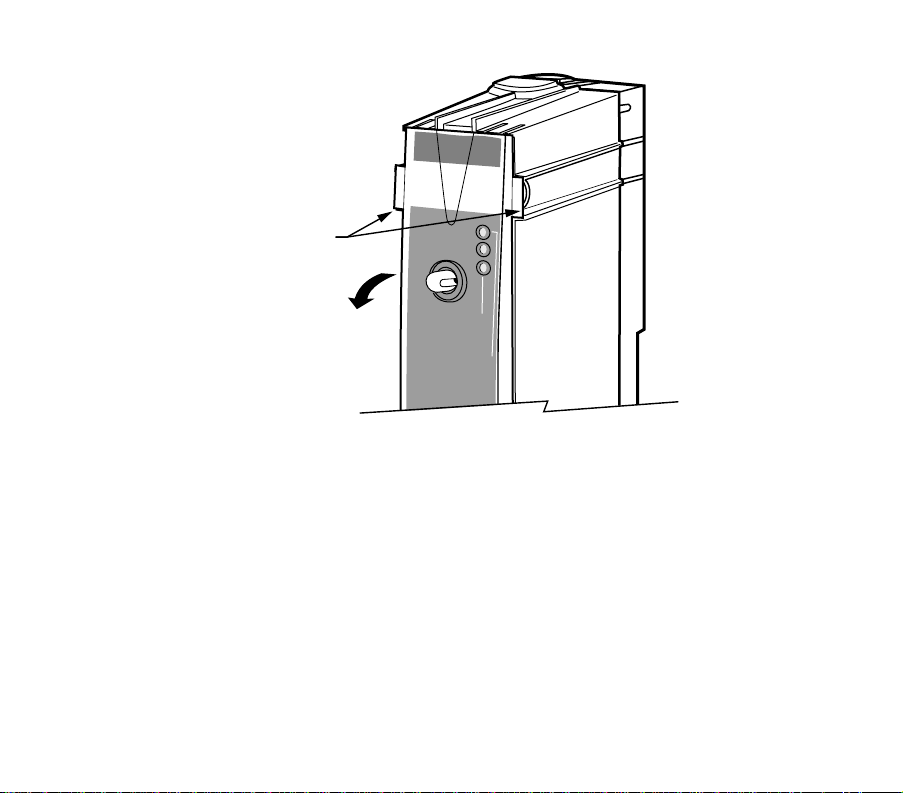
Operating Your Telephone Access Module
When installin
our Telephone Access Module,
our
installer used the telephone hookup connection practice
described in the CAUTION. Do not alter
our telephone
hookups without first consultin
our installer.
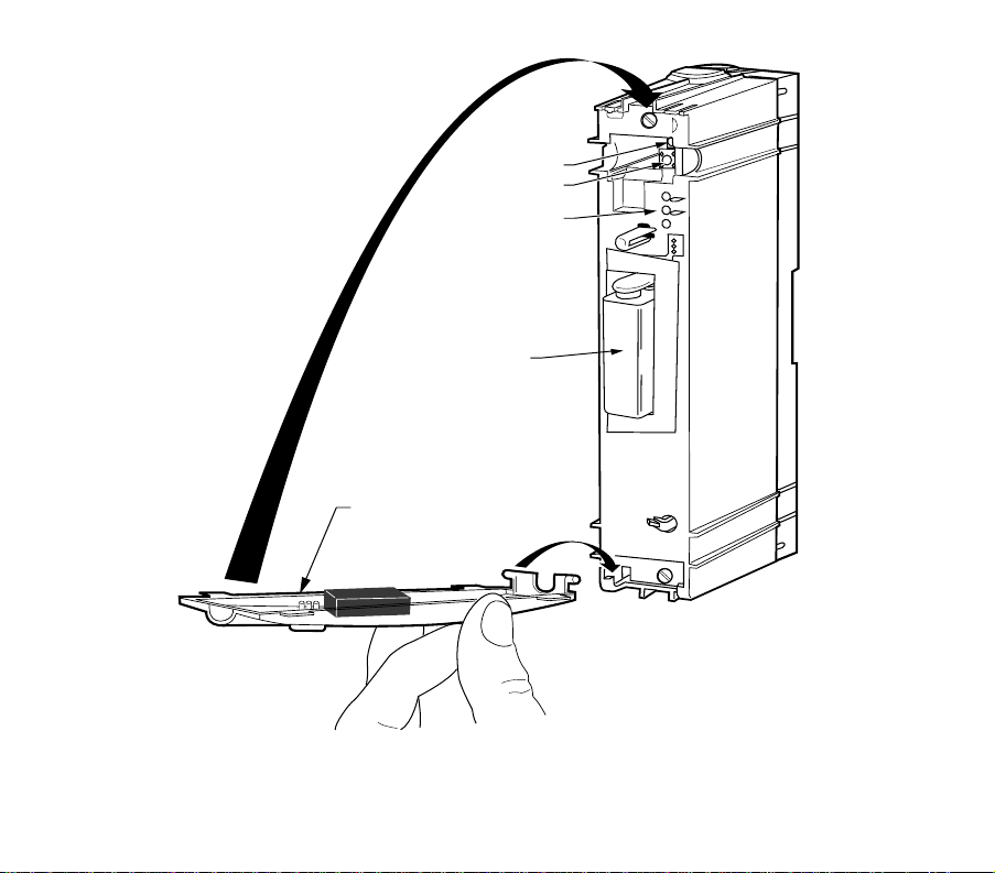
CAUTION
Incorrect Telephone Line Hookup Hazard.
Inability to call out can result in personal
injury or property damage.
Improper installation can result in blocked
phone lines and inability to make 911 and
other emergency-reporting phone calls.
Alwa
s connect the Telephone Access Module
first in line. When a monitored securit
s
stem
is installed, connect the Telephone Access
Module second in line.
Observin
this practice ensures that
theTelephone Access Module drops off the line
to allow priorit
to the house telephone.
Calling Your Telephone Access Module
Carefull
review the User and Confi
uration Menus
before operatin
our Telephone Access Module.
IMPORTANT:
The Telephone Access Module is designed to
provide remote access to your thermostat set-
tings and information. To access this informa-
tion or make changes, you must connect with
the Telephone Access Module from an out-
side line. If you want to access the Telephone
Access Module locally, you need to use a sec-
ond phone line or call from a cellular tele-
phone.
PASS CODE
You will be asked to respond to the quer
, “Enter
our
Pass Code followed b
the # ke
.”
You will be asked to enter a four-di
it Pass Code. The
default Pass Code is 1 2 3 4. You can chan
e this Pass
Code an
time b
enterin
the Confi
uration Menu. See
Confi
urin
Your Telephone Access Module section for
complete instructions.
If the pass code is not entered
within six seconds after the
Telephone Access Module
answers the telephone and
be
ins transmittin
data, han
up
and call a
ain after 30 seconds.
The transmission of data is for
future applications. Be sure to
send in the Re
istration Card to
receive notice of future updates.
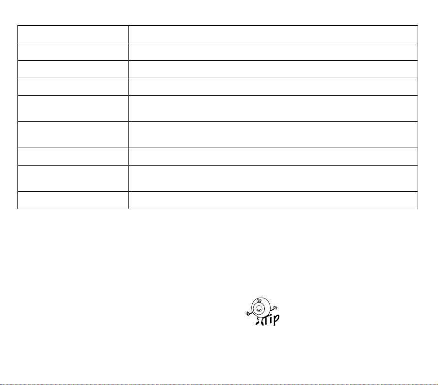
ALERT MESSAGES
You will hear this messa
e, “A (alert messa
e) is active.”
The Telephone Access Module indicates an active alert
messa
e immediatel
after
ou enter
our Pass Code.
See Table 1 for a list of the alert messa
es and
correspondin
causes. For additional information, see
Confi
urin
Your Telephone Access Module section.