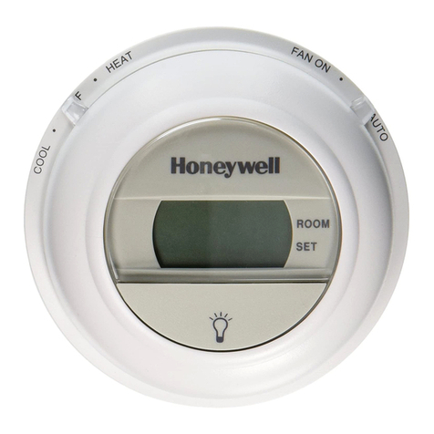
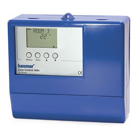
The RF link between the Room Thermostat (DT92E) and the Programmer
(ST9420C) in Honeywell system packs is pre-configured at the factory
and therefore both units should be installed at the same site.
• Ifproductsfromindividualsystempacksareseparated,ormixed
with other pre-configured system packs during installation, or a
faulty unit is being replaced, the desired units must be specially
configured to allow them to communicate with each other. This
process is called Binding. Please refer to section 5 Binding /
Rebinding Procedure.
• DT92E or ST9420C will not communicate with other RF products
that use different frequencies or communications protocols.
• TheDT92Eroomthermostatrequiresno powersourceotherthan
the batteries provided.
• The ST9420C Programmer requires a permanent 230V~ supply.
• The Programmer should be installed and powered up before
commencing the Room Thermostat installation.
Section Page
1 INSTALLING THE ST9420C PROGRAMMER............ 3
1.1 Mounting ST9420C .................................................................. 3
1.2 Mounting options ..................................................................... 3
1.3 Wiring ST9420C....................................................................... 3
1.4 Final Assembly......................................................................... 3
1.5 ST9420C Internal Wiring.......................................................... 4
1.6 Sundial Plan Wiring Diagrams (S, Y, C, W plans) .................... 4
1.7 Replacement Wiring ................................................................ 5
1.8 Replacing Other Manufacturers’ Time Controls ...................... 5
1.9 Powering Up ST9420C ............................................................ 5
2 INSTALLING THE DT92E ROOM THERMOSTAT ...... 6
2.1 Locating DT92E ....................................................................... 6
2.2 Powering Up DT92E ................................................................ 6
2.3 Signal Strength Test................................................................. 6
2.4 Mounting DT92E ...................................................................... 7
3 SYSTEM CONFIGURATION: ST9420C ..................... 8
3.1 ST9420C Installer Modes......................................................... 8
3.2 Boiler Service Reminder / Shut-down Feature......................... 8
3.3 Installer Setup.......................................................................... 9
3.4 Installer Setup Flowchart ....................................................... 10
3.5 Set Service............................................................................. 10
3.6 Change PIN ........................................................................... 12
3.7 What the User Will See When a Service is Due..................... 12
3.8 Resetting the Service Timer Function.................................... 12
4 SYSTEM CONFIGURATION: DT92E ....................... 13
4.1 DT92E Installer Mode ............................................................ 13
5 BINDING / RE-BINDING PROCEDURE ................... 14
5.1 Binding................................................................................... 14
5.2 ST9420C Guided Binding Menu............................................ 14
5.3 Binding Menu Display............................................................ 14
5.4 Binding Menu Flowchart........................................................ 14
5.5 How to Bind DT92E to ST9420C............................................ 15
6 COMMISSIONING THE SYSTEM............................. 16
6.1 Completion Checklist for Installation ..................................... 16
Within a typical house the two products should communicate reliably
within a 30m range. It is important to take into consideration that walls
and ceilings will reduce the RF signal. The strength of the RF signal
reaching the Programmer depends on the number of walls and ceilings
separating it from the room thermostat, as well as the building construction
- the diagram below illustrates an example of typical signal strength
reduction. Walls and ceilings reinforced with steel or plasterboard walls
lined with metal foil reduce the RF signal significantly more.
RF Signal Propagation
Installation Notes Installation Sequence: Step by Step
Typical example of Building Fabric Signal losses
= Signal Strength
Wall Wall Wall
Ceiling
Max. Signal Length 30 metres
