Honeywell DR Graphic User manual

43-TV-33-214 iss.2 GLO May 2015 UK 1
DR Graphic recorder - Installation Instruction
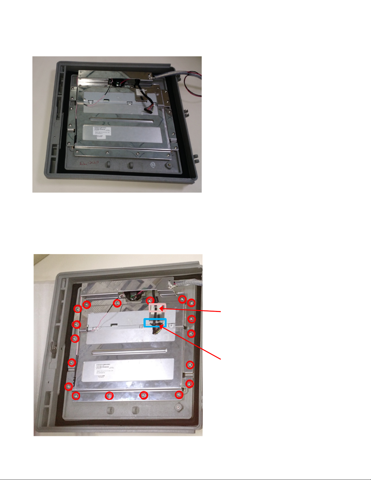
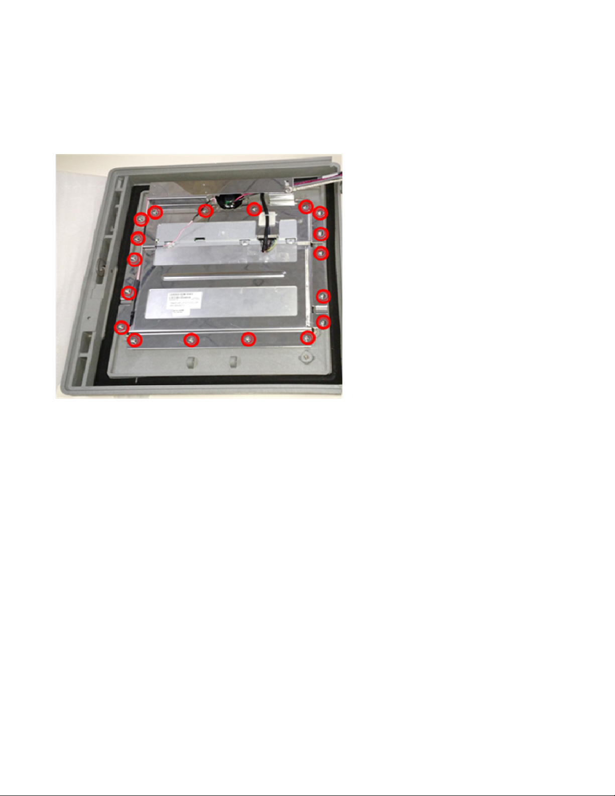
Display Replacement
DR Graphic Recorder
This Installation Instruction sheet is intended as a guide for replacing or installing hardware and for setting up
functionality in the recorder. Refer to the User manual for detailed operational requirements.
The DR Graphic recorders are designed for ease of assembly with minimal disturbance to the rest of the unit. If unsure,
please return the unit to your supplier for repair or upgrade.
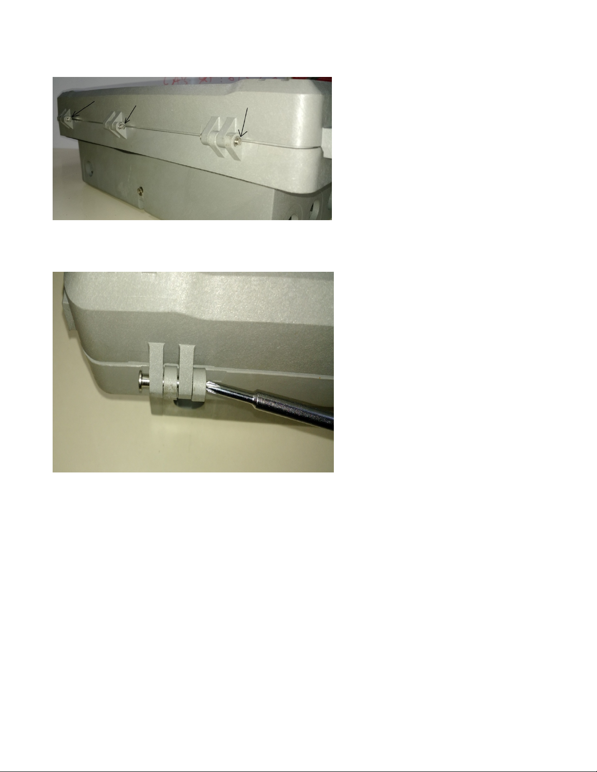
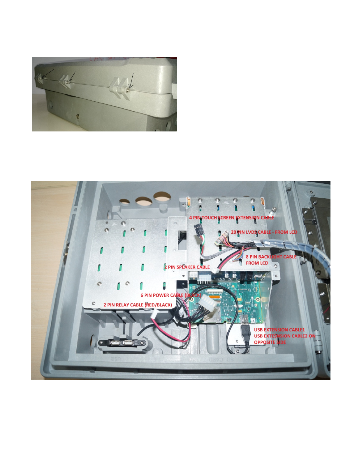
Opening the recorder and removing the internal chassis of the recorder should only be performed under the following
circumstances:
When an item of hardware requires individual replacement.
When an item of hardware is to be retrospectively fitted.
In all other instances it is recommended that the complete unit be returned to an authorized agent or service centre. For
Agency Approved recorders the product needs to be upgraded or repaired by an Authorized Repair facility
WARNING
HAZARDOUS VOLTAGES
Disconnect all the power, CJCs and IO cabling to the recorder before removing the IO cards chassis or power supply
chassis and attempting any maintenance procedures.
SAFETY TESTS
Upon completion of service procedures detailed in this instruction verify the installation per the installation section of the
product manual.
Failure to comply with these instructions could result in death or serious injury
CAUTION
OBSERVE ANTI-STATIC PRECAUTIONS
Refer to BS EN61340-5-1: 2001. Basic specification. Protection of electrostatic sensitive devices.
Full anti-static precautions MUST be observed when in contact with the electronics of your recorder.
SAVE DATA, SETUPS AND LAYOUTS
Removal of PCBs and battery back-up will result in the loss of all non-volatile data.
Ensure all data and set-ups are saved.
Failure to comply with these instructions may result in product damage.

43-TV-33-214 iss.2 GLO May 2015 UK 2
Before attempting to repair or upgrade a recorder, it is advisable to clear sufficient work space so components such as
the front panel can be rested on the work surface without getting scratched or damaged. For display subassembly
installation/replacement it is required to remove the recorder from the mounting brackets
Removing cables
1. Open the door (Bezel side) of the unit by unlocking the latch.
2. Remove the 2x No.4/40 screws of slanted chassis plate shown in circles below in Figure 1 and remove the slanted
chassis plate.
3. Remove the slanted chassis plate on the back side of the IO card chassis.
See Figure 2.
Figure 1
Removing slant chassis
Figure 2
Removing Cabling
inside the slant

43-TV-33-214 iss.2 GLO May 2015 UK 3
4. Remove all the cables attached to the processor board as shown in Figure 3.
Separating the Bezel and Case
Once all the cables are removed from the CPU board; the next step is to separate the case from display bezel
assembly.
5. Close the door of the unit.
Figure 3
Processor board with
all cables
removed
Figure 4
View of DR Graphic
from hinge side

43-TV-33-214 iss.2 GLO May 2015 UK 4
6. Remove the three criclips to unlock the hinge pins shown by the black arrows in Figure 5. The circlips can be
removed by pulling them out using a pair of needle nose pliers.
7. Push out the hinge pin using a pointed tool like screw driver as shown in Figure 6.
Once the hinge pins are pushed out by 5 to 7mm use a nose plier to pull the three hinge pins out of the hinges.
Figure 5
Positions of circlips
Figure 6
Removing hinge pin

43-TV-33-214 iss.2 GLO May 2015 UK 5
Dissembling display subassembly
8. Once the hinge pins are removed separate out the display bezel assembly and case.
9. Cut the cable tie shown in Figure 8.
10. Remove the LCD data cable from LCD connector shown in Figure 8.
11. Unwrap the wires from the wire wrap.
Remove the earth braid connected on LCD bracket top side. This earth braid needs to be reused with the new
display subassembly.
12. Remove the 18x No.8/32 screws, shown in red colour in Figure 8, from the LCD bracket
Figure 8
Removing display bracket and
LCD data cable
Figure 7
Dissembled display bezel
assembly
Cut the cable tie
Remove the LCD data cable
from LCD connector

43-TV-33-214 iss.2 GLO May 2015 UK 6
13. Remove the old LCD display subassembly along with its wires. Make sure to carefully remove the LCD from its
place as the touch screen is located right below it.
See Figure 9.
14. Make sure that the new display subassembly has the following parts attached to it.
a. 20 pin LVDS data cable connected on back side of the LCD to LCD data connector
b. 8 pin backlight cable connected to the green coloured backlight controller PCB
c. 2x backlight cables of LCD connected to the green coloured backlight controller PCB on sides
d. Metallic bracket on which the LCD is mounted
15. Cut the cable tie of the touch screen extension cable and separate out the touch screen extension cable
16. Make sure that the speaker cable and touch screen extension cable are in their proper place.
17. Fit the LCD back in its place and align all holes of LCD bracket with bezel boss holes. When bending the touch
screen extension cable make sure that it does not extend beyond the step inside the bezel just below the gask
Figure 10
New display assembly
Figure
2
Q
X recorder
Figure 9
Removing old display assembly
for replacement

43-TV-33-214 iss.2 GLO May 2015 UK 7
18. Route the LCD data cable through the LCD bracket as shown in Figure 11 and then hold it in place with a cable tie.
19. Make sure that LCD backlight cable, data cable and touch screen extension cable are routed to the right side below
the LCD bracket step.
20. Reconnect 18x #8-32 screws on LCD bracket.
See Figure 11.
21. Reconnect the Earth braid on the LCD bracket.
22. Put a spiral wrap around all the cables.
Figure 11
Reconnecting display bracket
and routing cables on bezel side

43-TV-33-214 iss.2 GLO May 2015 UK 8
Re-assembling the Unit
23. Put back the display bezel assembly on top of the case and insert the hinge pins shown by black arrows.
24. Attach the circlips to the hinge pins which lock the hinge pins in place.
25. Again open door to connect all the cables inside the case.
26. Figure 13 and the following table provide information on different cables used and where they should be connected.
Connectors of all the cables are polarized, make sure to connect the connectors as per notch direction.
Figure 13 – Cables to be connected inside slant chassis plate to the CPU board
Figure 12
Reconnecting hinge pins

43-TV-33-214 iss.2 GLO May 2015 UK 9
Sr. No. Cable Description Source - Description
1 Relay extension cable – for status of power
relay Power supply Board to Backplane board (J10)
2
Touch Screen Extension Cable – for
extending the touch screen connections
from the touch screen to the CPU board
Touch screen in Bezel to CPU board in case (J5 – Notch
on cable should face EXT SD connector – J8)
3 Backlight Cable – For backlight driver
board
Backlight driver board to backlight connector on the CPU
board (J14)
4 LVDS Cable – For LCD data From LCD in bezel to CPU board (J11)
5 Speaker cable – For extending the speaker
connections
Speaker to speaker connector on the TVDRG2 backplane
board (J6)
6 Earth Braid – For strong ground
connection From LCD bracket to the IO cards chassis
7 6 Pin Power Cable Power Supply Board to Backplane Board (J10)
27. Connect all the cables as per the information in the above table and as shown in Figure 13.
Figure 13
Cables reconnected inside the
slant chassis plate

43-TV-33-214 iss.2 GLO May 2015 UK 10
28. Replace the slanted chassis plate and fit it back along with the earth braid using 2x No.4/40 screws.
29. Make sure all the screws shown in red and green colour in Figure 14 are connected back.
30. Reconnect the CJCs, IO cabling and Power cable as required.
31. Close the door.
32. If the recorder has been removed from the panel, secure it back into the panel using the mounting brackets.
Copyrighted Materials. For more information please contact your supplier.
Figure
14
—
Reconnecting slant chassis & IO card chassis
Other manuals for DR Graphic
1
Table of contents
Other Honeywell Voice Recorder manuals

Honeywell
Honeywell DR4300 Series Guide

Honeywell
Honeywell X Series User manual

Honeywell
Honeywell ERX 350 User manual

Honeywell
Honeywell DR4300 Series User manual

Honeywell
Honeywell X Series User manual

Honeywell
Honeywell X Series User manual

Honeywell
Honeywell DR4300 Series User manual

Honeywell
Honeywell DR4500A Manual

Honeywell
Honeywell DR4500A User manual

Honeywell
Honeywell DPR180 User manual