Honeywell ERX 350 User manual

ERX 350 Recorder Quick Start Guide
FD-604 | Version 1 | October 2017
Honeywell Process Solutions | Mercury Instruments
512 Virginia Drive, Ft. Washington, PA 19034 USA
855 251-7065 – United States & Canada | 302 669-4253 – Outside the United States
MI-TAC-Support@Honeywell.com | www.honeywellprocess.com

Copyright 2017 . Honeywell Process Solutions. All rights reserved.
Information in this document is subject to change without notice. The software described in
this document is furnished under a license agreement or non- disclosure agreement. The
software may be used or copied only in accordance with the terms of those agreements. No
part of this publication may be reproduced, stored in a retrieval system, or transmitted in any
form or any means electronic or mechanical, including photocopying and recording for any
purpose other than the purchaser's personal use without the written permission of Honeywell
Process Solutions.
For technical assistance, email at MI-TAC-Support@Honeywell.com.

1 Introduction
The Honeywell ERX 350 is a microprocessor-based, stand-alone, self-powered data recorder that
measures gas pressure(s), gas temperature, case temperature, and power supply voltages. Sampled
measurements, logged Audit Trail data, Alarms entries, User change events, and operating parameters are
stored in non-volatile memory and may be retrieved directly with a laptop computer, PC, mobile devices,
or remotely via modem. ERX 350 Recorder is capable of recording audit trail data into (up to five)
independent Loggers. Each of the loggers can be configured for; number of items, logging interval and
record size. Recorder configuration (and other activity) is possible via the HMI feature.
The ERX 350 offers large feature set along with a path forward to support new technologies.
The ERX 350 installation consists of mounting and wiring ERX 350 according to the instructions given in
the User’s Manual. Read the installation information provided in the ERX 350 User’s Manual and refer to
the section “Model number interpretation” for more details on ERX 350 model you have selected.
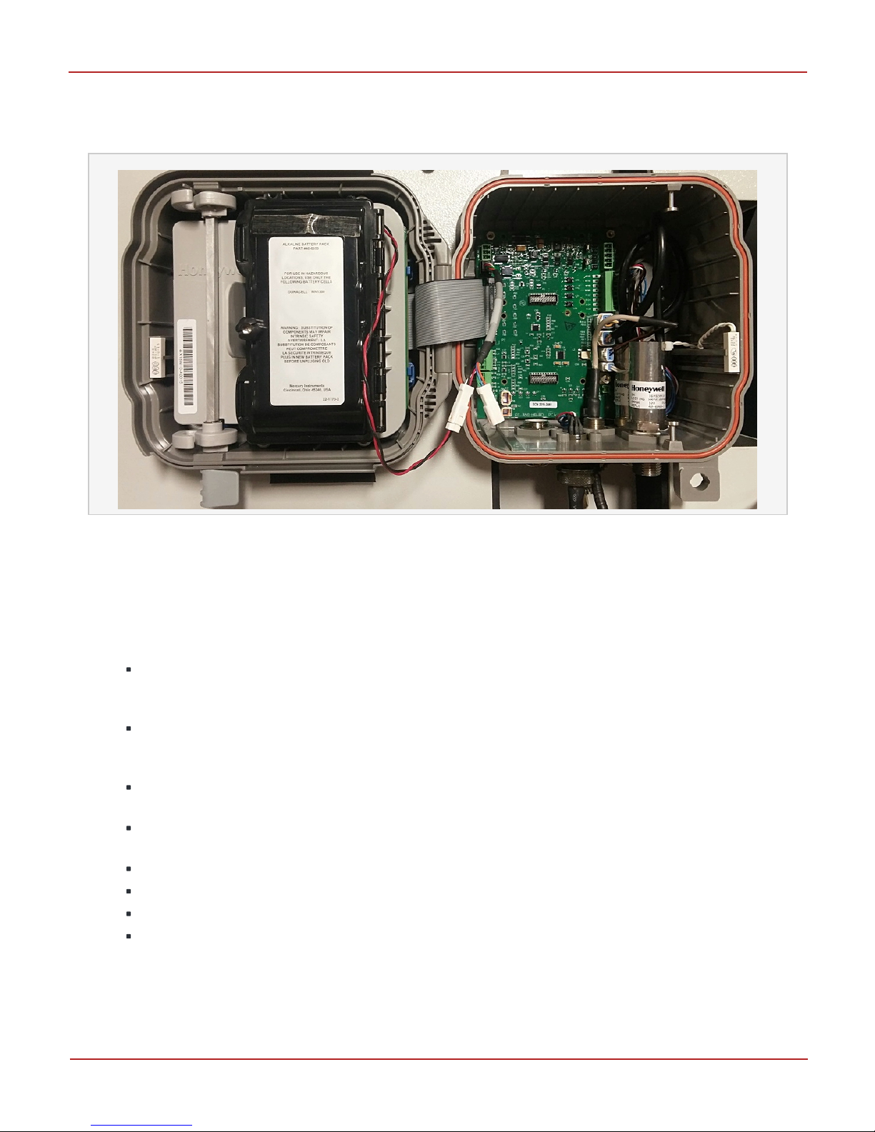
1.1 Components inside the ERX 350
Depending on options ordered, the following components may be installed or provided with the ERX 350
when shipped:
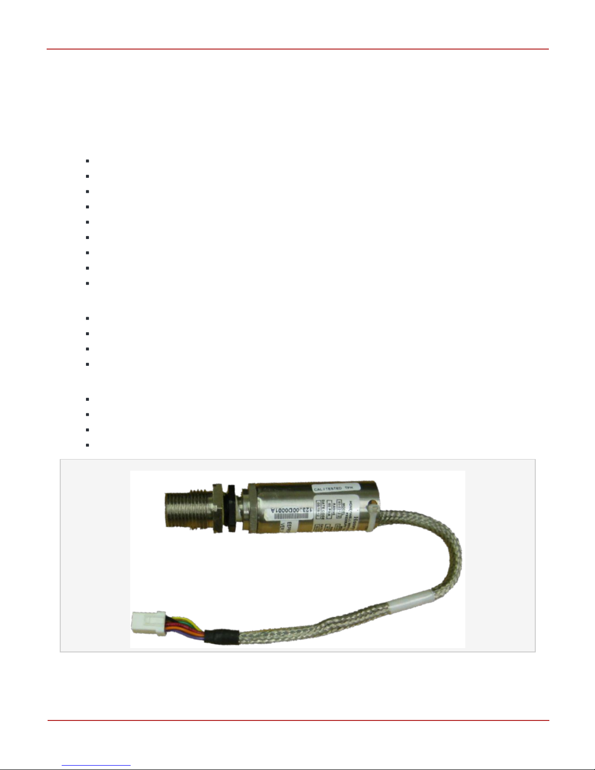
Pressure transducers (up to 2 transducers, already connected)
Temperature probe (already connected)
Landline or Cellular Modem (already connected)
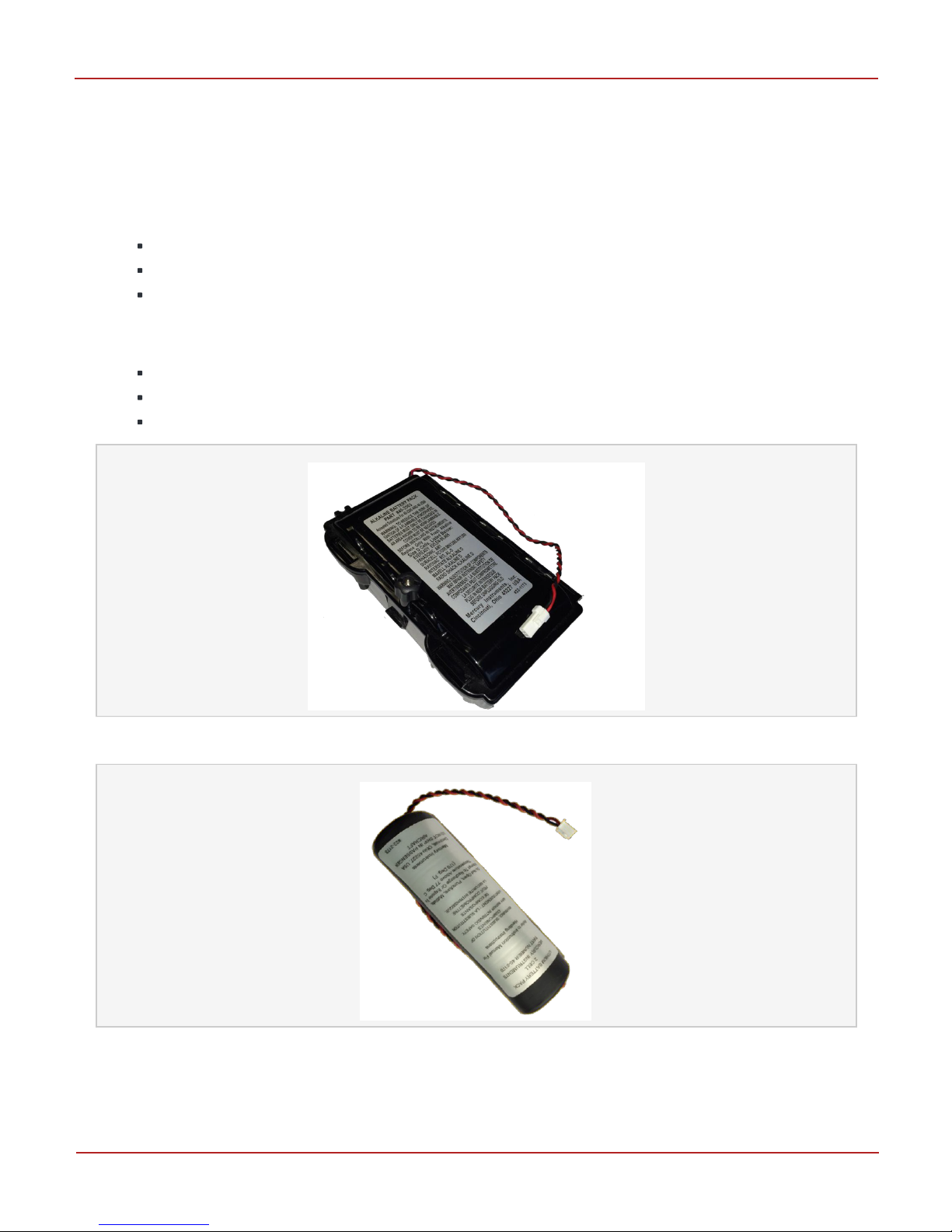
Battery Pack
IrDA Dongle & USB Cable
1.2 Unpacking the ERX 350
1. Remove the contents from the box and check the shipment against the invoice to ensure the
components ordered are provided.
2. Report any shortage or shipping damages to your nearest Honeywell Distributor.
1 Introduction
Honeywell | 1

2 Powering the ERX 350
2.1 Battery Power Units
The Connections are made at P5 connector on the ERX 350 I/O Board. The ERX 350 unit can be operated
from the following battery power:
40-6050 (4-cell Alkaline) – 5 year operating life under specified conditions
40-6048 (2-cell Lithium)
Dual set of 40-6048 (2-cell Lithium) – extended life or heavy usage / comms applications.
Item 1061 (Battery Type) is used to select the type of battery pack that is to power the instrument. Verify
item 1061 is correctly configured for the installed battery pack.
0 = 4 D-Cell Alkaline Receptacle Pack, for EC350 only - Default
1 = 2 D-Cell Lithium Sealed Pack, for EC350 only
2 = Dual 2 D-Cell Lithium Sealed Packs (connected in parallel), for EC350 only
Figure 2-1: 40-6050 (4-cell Alkaline)
Figure 2-2: 40-6048 (2-cell Lithium)
2 Powering the ERX 350
Honeywell | 2

The graphic below shows an alkaline battery pack connected. The ERX 350 I/O Board is on the right.
Note the twin connector (two connector pair) provided for the battery connection. Only one is being used
in this photo.
Figure 2-3: Alkaline Battery Pack Connected
2.2 External Supply Power Units
The Connections are made at TB1 connector on the ERX 350 I/O Board.
2.2.1 Specifications for external power supply
The input voltage range for using an externally supplied DC power source is +5.0 to +15.0 VDC.
The Honeywell power 9 VDC, 400 mA power pack (p/n: 40-2291) can be used as an external
power source
Connections for the external supply are made at connector TB1 on the ERX 350 I/O Board.
Terminal-1 of TB1 closest to the top of the I/O Board is negative (-) and Terminal-3 is positive
(+) input. These Battery Packs can be connected to the I/O board using cable p/n: 40-6045.
A backup battery pack may also be installed to keep power on the instrument in situations
where the external power is interrupted.
Notice: for Class 1, Div. 2 compliant installations, only the following Battery Packs are
approved:
40-6048 (2-cell Lithium)
40-6050 (4-cell Alkaline)
40-6064 (4-cell Alkaline with 47 ohm Res).
Configure the External Supply Low Alarm Limit (Item 795) to a value of 5.0 to 7.0 volts. Note
that the default value of Item 795 is set to -1.0 to effectively disable the Alarm Item 796 when
external supply is not being used.
2 Powering the ERX 350
Honeywell | 3

2.2.2 General Power Supply Notes:
Supply power is measured on a 10-minute interval (battery / external supply voltages)
An Item is not used to choose between externally supply and battery powered
For Alarm triggering – three (3) consecutively low readings are required to the trip the associate
Alarm. This is done to help guard against falsely setting alarm due to a supply glitch
The Low Battery Voltage Alarm (Item 99) will not set if there is an External Supply voltage at
TB1 greater than the Battery voltage by over 1.0 volt
2 Powering the ERX 350
Honeywell | 4

3 General Connection Diagram
3.1 I/O Board Connections
Note:
ERX 350 does not use Pulse Outputs A – B – C
Metrological Jumper is generally not required for ERX (Recorders)
Digital Input connections are made at: SW1 – SW2 – SW3 (Input ‘SW4’ is not utilized)
See Items 762 – 764 for Digital Input configurations to enable Digital Input Alarms.
Figure 3-1: I/O Board Connections
3 General Connection Diagram
Honeywell | 5

4 Connecting a Pressure Line
Shown below are the locations for P1 and P2 Pressure Transducer connectors.
Use a pressure connector kit to connect the required pressure line(s) to the ¼ inch NPT fittings on the
back side of the ERX 350 enclosure.
Hold pipe wrench on flats when installing a pressure line on the pressure transducer connector to ensure
proper sealing and to avoid stress loading on the composite case.
Figure 4-1: Locations for P1 and P2 Pressure Transducer connectors
Note: To avoid over-pressurizing the transducers, it is extremely important to ensure the pressure
transducer(s) can handle the pressure from the gas line(s).
Check Items 570 (P1 Transducer Range) / 571 (P2 Transducer Range) BEFORE applying live gas
pressure to the ERX 350.
4 Connecting a Pressure Line
Honeywell | 6

5 Pressure / Temperature Key Items
The ERX 350 can be configured to measure Gas Pressure from two independent Digital Pressure
Transducers as well as Gas Temperature from a Thermistor-based Temperature Probe. Listed here are
key Items for the ERX 350 for P1, P2, and T1 measurement operations:
Configuration Items:
586 (Sample Interval) –> Seven options ranging from 1 to 60 second intervals
549 (P1 Pressure Units) –> Nine selectable units options for P1
550 (P2 Pressure Units) –> Nine selectable units options for P2
551 (T1 Temperature Units) –> Four selectable units options for T1
552 (P1 No of Decimal for P1 Press) –> Decimal point location for P1
409 (P2 No of Decimal for P2 Press) –> Decimal point location for P2
1052 (P1 Transducer Enable) –> Yes/No (enable/disable measurement of P1 gas pressure)
1053 (P2 Transducer Enable) –> Yes/No (enable/disable measurement of P2 gas pressure)
1055 (T1 Temp Probe Enable) –> Yes/No (enable/disable measurement of T1 gas temperature)
Measurement Items:
500 (P1 Gas Pressure) –> measured value of P1 gas pressure
501 (P2 Gas Pressure) –> measured value of P2 gas pressure
502 (T1 Gas Temperature) –> measured value of T1 gas temperature
503 (Case Temperature) –> measured value of case / ambient temperature (on board)
Status Indication Items:
569 (P1 Transducer Type) –> Gauge, Absolute, or None (status Item – not configurable)
409 (P2 Transducer Type) –> Gauge, Absolute, or None (status Item – not configurable)
570 (P1 Pressure Range in PSI)–> status Item – not configurable
571 (P2 Pressure Range in PSI)–> status Item – not configurable
Figure 5-1: Pressure Transducer
5 Pressure / Temperature Key Items
Honeywell | 7

6 IrDA Connection via USB Cable
Connect the IrDA communication USB cable to ERX 350 as shown in the image below. Connect the other
end of the cable to a USB port on the computer where MasterLink is installed. See second image.
The Icon will be showing when the ERX 350 is ready to communicate in IrDA mode. After an
inactivity timeout period, the unit will automatically turn off the IrDA subsystem to save battery
power. Icon will be turned off.
To help save Battery life - remove the entire IrDA adapter from the ERX 350 when IrDA
communications are no longer required
See MasterLink R510 User Guide to configure the software setting for IrDA communication
6 IrDA Connection via USB Cable
Honeywell | 8

7 Serial Connections via RS-232 or RS-485
Connections to the ERX 350 serial communication interface are shown in the image below. Interface
options at TB4 on the I/O Board allow for RS-232 or RS-485 (2-wire).
RS-232 Connections:
TXD is at TB4 pin 1
RXD is at TB4 pin 2
GND is at TB4 pin
RS-485 Connections (2-wire):
‘A’ is made at TB4 pin 1 (TXD)
‘B’ is made at TB4 pin 2 (RXD)
Jumpers: JP1 and JP2 positions:
RS-232: Jumpers on pins: B-C
RS-485: Jumpers on pins: A-B
Ensure Item 1220 (Serial Interface Type) is configured for the appropriate serial interface type:
RS-232 or RS-485
7 Serial Connections via RS-232 or RS-485
Honeywell | 9

8 HMI (Human Machine Interface) Access Levels 0 – 3
The ERX 350 can be operated in the following four HMI User Access levels:
HMI Level Description
HMI Level 0 User defined Scroll List mode. User configured list of up to 18 items can be displayed
on the HMI LCD. No passkey to access this mode. After the keypad is active, use the
or buttons to scroll up or down through the available list of items. Note:
The items in this mode are read-only. All Items are snap-shot (static) values taken at
time User entered HMI Level-0.
HMI Level 1 Structured menu format with submenus used for viewing the instrument settings and
some live parameters. The items in this mode are also read-only (no configuration
changes).
No passkey to access this mode. Note that Pressures, Temperatures, and Power Supply
measurements are live readings updating once per second.
HMI Level 2 Structured menu format with submenus used for viewing and configuring many of the
parameters (Items) of the ERX 350. A passkey is required to access this mode. Level-2
menu also includes submenus to check/validate P and T measurements, Clear Alarms,
Force Alarm/Schedule Call-Ins, enter User Shutdown mode, Reset or Change Battery,
etc.
HMI Level 3 Structured menu format with submenus used for viewing and configuring many of the
parameters (Items) of the ERX 350. A passkey is required to access this mode. Level-3
menu also includes submenus to calibrate P and T probes, Clear Alarms, Force
Alarm/Schedule Call-Ins, enter User Shutdown mode, Reset or Change Battery, etc.
Level-3 menu also includes the Advanced Configuration (ADV CONFIG) menu to access
every Item directly.
EXIT User selects this choice and then presses the OK key to return back to normal recorder
mode
Main menu screens for the four HMI User Access Levels L0 – L3: (plus HMI EXIT screen)
8 HMI (Human Machine Interface) Access Levels 0 – 3
Honeywell | 10

9 HMI Menu Navigation Buttons (Capacitive Touch Keys)
The ERX 350 has six capacitive touch keys (button) that are used to operate the HMI.
Figure 9-1: HMI Menu Navigation Buttons
When the HMI is inactive (units is displaying normal Recorder screen) – the six keys are in a ‘locked’
state and are considered disabled. See next section on enabling (unlocking) the HMI keys to access the
various levels.
The following table lists main menu keys.
Keys Description
Up and Down Arrow keys:
Navigate Up or Down menu tree and scrolling through lists
Increase / decrease digit values
Main menus allow navigating in reverse direction (roll backwards)
Left and Right Arrow keys:
Move cursor left or right to next or previous digit or decimal point
OK (Enter) key:
Used for accepting input entries
Confirming menu selections
Escape (Esc) key:
Used to exit back / escape out of a menu node (go back one tree branch)
Cancel an entry
9 HMI Menu Navigation Buttons (Capacitive Touch Keys)
Honeywell | 11

10 Activating HMI (Unlocking Keys)
1. Unlock Key pads - Press and hold and at the same time until the Display Test
screen appears (shown here)
2. Press the - you will now see HMI Menu for Level L0 (Item Scroll List)
Note: The Icon: will appear on the far right bottom corner of the LCD to indicate HMI User Access
is enabled.
Use to navigate up / down to any of the four HMI Menus Levels L0 – L3.
To select a particular menu Level 0 - 3 press key
10 Activating HMI (Unlocking Keys)
Honeywell | 12

11 HMI Level 2 or 3 Passcode Entry
1. Unlock Keys - Press and hold and - see section above on Activating HMI.
2. Press the and you will see Level-0 Menu. Use or to scroll to L2 or L3 of
the HMI Main Menu screen. L2 Main Menu shown here.
3. Once you have scrolled down to the desired L2 or L3 Main Menu selection screen - Press
to view the Passcode main screen
4. Passcode screen will not appear if you have already properly entered the passcode for that Level.
11 HMI Level 2 or 3 Passcode Entry
Honeywell | 13

12 HMI - Changing an Item Value
If a value (Item) can be changed – then press and the 10 underlines _ _ _ _ _ _ _ _ _ _ will not be
shown and be replaced by a single cursor _ normally starting at right most digit position (except for
Pass code entry).
Use or to move the cursor left or right to the desired digit. Once cursor is under the desired digit
– then it can be changed – see next step.
Use or to increment or decrement a digits value that is positioned above the cursor.
Finally – press when value is set properly to store in non-volatile memory.
Example below – change SITE ID 1 from 00000000 to 00001000.
12 HMI - Changing an Item Value
Honeywell | 14

13 HMI Icons
The following table lists main menu keys.
Keys Description
Heart Beat: indicates normal operation (3 sec rate when in normal Recorder mode – and 1 sec
rate when in HMI mode).
Lock/Unlock: indicates whether the unit is metrological sealed state or not
Not applicable for Recorders (no metrological aspects)
Battery: indicates a low power supply condition (Bell Icon does not activate for this
condition).
Alarm: indicates any Alarm condition (excluding low power supply conditions).
Also - see Icon ‘D’ below.
IrDA Comm: indicates that the IrDA adapter (magnet) is present.
Escape key function indicator. On indicate key should be functional.
Navigation key function indicator: used to help indicate which keys are active at the moment.
Icon(s) being On indicate key should be functional.
‘OK’ (Enter) key function indicator. Used to accept values or enter a particular screen page of
HMI. On indicate key should be functional.
D Icon indicates Alarm Output hardware signal is turned on.
A-B-C Icons are not used for ERX 350
Smile: indicates the HMI is active. The navigation keys are functional.
Star / Asterisk: indicates a measurement is in process. (e.g. P1 being updated)
13 HMI Icons
Honeywell | 15

14 Cloud Link 4G Modem (Optional Modem Interface)
The Cloud Link 4G Modem is connected to the ERX 350 using an RS-485 interface. Connections are made
at the TB4 terminal block on the I/O Board (pins 1, 2, and 5).
1. Ensure Item 1458 (Modem Type) is configured to ‘Cloud Link’
2. Refer to the Cloud Link Quick Start Guide and User Manual for more information on using the
Cloud Link Modem.
3. Ensure to the RS232/485 section switch is in position to operate in RS-485 mode. The switch must
be moved to position closest to power connectors on Cloud Link modem. See image below – switch
is in position to select RS-485
4. Ensure Cloud Link Item 3075 is configured for RS-485 mode
14 Cloud Link 4G Modem (Optional Modem Interface)
Honeywell | 16

15 ERX 350 Call-In (Optional Modem Interface)
The ERX 350 can be operated to call in to Host systems due to Alarm condition events and/or on a
Schedule (as configured per date and time). Listed here are key configuration Items for the ERX 350 for
Call-In operations:
333 (Call-In Trigger) –> Alarm + Scheduled Calls
334 (Scheduled Call-In Date) –> Must be current date or future
335 (Scheduled Call-In Time) –> Must be in future by at least a few seconds
336 (Call-In Retry By) –> Set to ‘Instrument’
339 (Schedule Call Phone #1) –> set to appropriate IP # or landline tel #
784 (Alarm Call Phone #2) –> set to appropriate IP # or landline tel #
785 (Alarm Call Phone #1) –> set to appropriate IP # or landline tel #
786 (Failed Call Retry-A Interval) –> set to 10 minute or as required
787 (Failed Call Retry-B Interval) –> set to 10 minute or as required (typically 1440)
788 (Failed Call Retry-A Count) –> typically set to a value between 1-5 (e.g. 3)
821 (Modem Wake-Up Delay) –> for Cloud Link Modem set to a value 50 (5 seconds)
1406 (Dial Response Timeout) –> for Cloud Link Modem set to a value 90 (seconds)
15 ERX 350 Call-In (Optional Modem Interface)
Honeywell | 17
Other manuals for ERX 350
1
Table of contents
Other Honeywell Voice Recorder manuals

Honeywell
Honeywell DR4500A Manual

Honeywell
Honeywell DR4300 Series Guide

Honeywell
Honeywell DR4500A Manual

Honeywell
Honeywell X Series User manual

Honeywell
Honeywell X Series User manual

Honeywell
Honeywell DR Graphic User manual

Honeywell
Honeywell DR4300 Series User manual

Honeywell
Honeywell DR4300 Series Guide

Honeywell
Honeywell DR4300 Series User manual

Honeywell
Honeywell DR4500A User manual