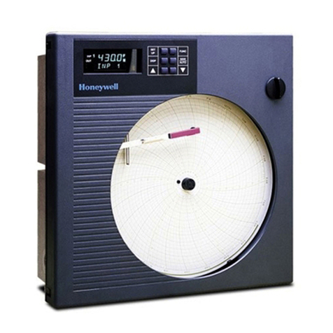
Honeywell DR4300 Series Guide

3/05 Replacement Kit Instruction 43-DR-33-87 1
Model DR4300/DR4500 Circular Chart Recorder
Replacement Instruction
Servo Motor Kit (30756114-501)
1.1 Summary
Document Number
Form: 43-DR-33-87
Effective: 3/05
Table of Contents
This instruction contains Servo Motor replacement instructions for the model numbers listed below:
Topic See Page
1.2 DR4501, DR45A1 - One Pen Classic Servo Motor Replacement 2
1.3 DR4501, DR45A1 - One Pen Classic Pen Alignment 3
1.4 DR4502, DR45A2 - Two Pen Classic Servo Motor Replacement 6
1.5 DR450T, DR450R, DR450W, DR45AT, DR45AR, DR45AW,
DR45AH, DR45AP Truline Recorder
9
1.6 DR4300 Recorder One Pen Models 12
1.7 DR4300 Recorder Two Pen Models 16
Symbol Definitions
WARNING
PERSONAL INJURY: Risk of electrical shock. This symbol warns the user of a
potential shock hazard where HAZARDOUS LIVE voltages greater than 30 Vrms,
42.4 Vpeak, or 60 Vdc may be accessible. Failure to comply with these
instructions could result in death or serious injury.
ATTENTION, Electrostatic Discharge (ESD) hazards. Observe precautions for
handling electrostatic sensitive devices.
WARNING Never access components inside the controller enclosure with power applied.

2 Replacement Kit Instruction 43-DR-33-87 3/05
1.2 DR4501, DR45A1 - One Pen Classic Servo Motor Replacement
Introduction
The procedure in Table 1 lists the steps required to replace the Servo Motor assembly in Models
DR4501, and DR45A1, One Pen Classic Models of the DR4500/DR4500A Circular Chart
Recorders.
The procedure assumes that the chart door is opened, the chart plate is swung out, and that the
power is removed.
Table 1 Procedure for Replacing the Servo Motor
Step Action
1 Note the location of the pen on the chart. Pull the pen lifter up to raise the pen from
the chart.
2 Remove the pen cartridge.
3 Remove the screw and lockwasher holding the pen arm to the servo shaft. Remove
the pen arm.
4 Note how the spring is connected from the servo plate gear sector to the chart plate.
Disconnect the spring from the servo plate.
5 The No.1 pen motor is located on the underside of the servo plate. Refer to Figure 2
(DR45A1) or Figure 3 (DR4501) for the location of the #1 Pen Motor and Cabling
information.
Disconnect the No. 1 pen motor cable from connector J5 on the top of the Main
printed circuit board.
6 Remove the pen motor wires from the wire holders on the chart plate and the top of
the case.
7 Disconnect green ground wires from lower left side of servo plate assembly.
8 Remove the other two screws holding the servo plate to the chart plate. Retain the
screws.
9 Pull the servo plate away from the chart plate and remove the two screws that hold
the old servo motor in place.
10 Install the new servo motor onto the servo plate and secure with the screws provided.
11 Reinstall the servo plate onto the chart plate. Reconnect the green ground wires to
the servo plate.
12 Dress the new motor cable with the other wires, using the new plastic tie wraps
provided, and place into the wire holders on the chart plate and top of case.
13 Connect the new motor cable plug to connector J5 on the Main printed circuit board.
14 Reconnect the spring to the servo plate as noted in step 4.
15 Replace the pen arm, lockwasher, and screw, but leave the screw slightly loose.
Replace the pen cartridge.
16 Push down the pen lifter and carefully position the pen to the location noted in step 1.
Tighten the pen arm screw.
17 Align the pen as described in Section 1.3.

3/05 Replacement Kit Instruction 43-DR-33-87 3
1.3 DR4501, DR45A1 - One Pen Classic Pen Alignment
Mechanical Alignment
CAUTION Align the pen mechanically as shown in Table 2 and then electrically as described in
Table 3. Never attempt to manually force the pen arms from the front, since this will damage
the pen mechanism.
Table 2 Procedure for Aligning the Pen Mechanically
Step Action
1 Turn off power, open the door, and lift the pen lifter up. Refer to Figure 1.
2 Unclip and remove the purple ink cartridges from pen 1 arm to provide a better
view of tip of arm.
3 Push the No. 1 pen sector gear down so that its uppermost teeth mesh with
teeth on the motor shaft gear. See Figure 1.
4 Slightly loosen the screw holding the No. 1 pen arm to the servo shaft.
5 Replace the No. 1 pen arm, lockwasher, and screw, but leave the screw slightly
loose.
6 Move the No. 1 pen arm so that its right tip aligns with the inside circumference
of the inner most circle in the center of the chart. Tighten screw.
Push sector gear
pen 1 (top pen)
for zero
Figure 1 Mechanical Alignment of Pen#1

4 Replacement Kit Instruction 43-DR-33-87 3/05
Electrical Alignment
If the group prompt “LOCKOUT” has been configured for “CALIB”, +VIEW”, or “MAX” selection, you
will not be able to access PEN 1 group prompt for electrical alignment. Set LOCKOUT to “NONE”.
Table 3 Procedure for Setting the Chart Time Line
Step Press Action/Result
1 Open the door, apply power, and wait for
the recorder to run its power up tests.
2 SET
UP
Until you see:
Upper Displa
y
Lower Display
SET UP
LOCKOUT
3
FUNC
Until you see:
Upper Display
Lower Display
LOCKOUT
One of the following
NONE
CALIB
+ CONF
+ VIEW
MAX
4
or
Until “NONE” is in the lower display.
ATTENTION Never leave the
“LOCKOUT” selection in “NONE.” Use
“NONE LOCKOUT” only when you intend
to make field adjustments to the
configuration
5 SET
UP
Until you see:
PEN 1
Lower Display
ALIGN
Upper Display
6
FUNC
You will see:
PEN 1 0
Lower Display
ALIGN
Upper Displa
y
The pen moves to an internal stop then
backs away and stops.
7
or
to move the pen to the zero position on the
chart (inner position of chart).
ATTENTION You can position the pen
over 1200 steps. Those steps are relative
units only. Step 0.0 is the inner most
position on the chart, and step 1200 is the
highest circumference position.

3/05 Replacement Kit Instruction 43-DR-33-87 5
Table 3 - continued
Step Press Action/Result
8 LOWR
DISP
You will see:
PEN 1 0 0
Lower Display
ALIGN
Upper Displa
y
The value adjusted in step 3 is entered into
memory.
9
or
to raise or lower the value in the upper
display (up to 1200) move the pen to the
highest chart range value (outer
circumference printed on the chart).
10 LOWR
DISP
to return to normal operation and enter the
span value into memory.

6 Replacement Kit Instruction 43-DR-33-87 3/05
1.4 DR4502, DR45A2 - Two Pen Classic Servo Motor Replacement
Introduction
The procedure in Table 4 lists the steps required to replace the #2 Servo Motor assembly in
Models DR4502, and DR45A2, Two Pen Classic Models of the DR4500/DR4500A Circular Chart
Recorders.
The procedure assumes that the chart door is opened, the chart plate is swung out, and that the
power is removed.
Table 4 Procedure for Replacing the #2 Servo Motor
Step Action
1 Refer to Figure 2 (DR45A2) or Figure 3 (DR4502) For the location of the #2 Pen
Motor and Cabling information.
2 Disconnect the No. 2 pen motor cable from the connector on the top of the Main
printed circuit board. See below for connector location.
Model DR4502 Model DR45A2
J7 J6 or J5
3 Remove the wires from the wire holders on the chart plate and the top of the case.
Very carefully cut the nylon strap surrounding the wires. BE CAREFUL NOT TO CUT
THE WIRES.
4 Remove the screws holding the motor to the servo plate and remove the motor.
5 Install the new motor to the servo plate and secure with the screws provided.
6 Dress the Pen motor cables with the other wires, using the new plastic tie wraps
provided, and place into the wire holders on the chart plate and top of case.
7 Connect the new pen motor cable plugs into the connector locations on the Main
printed circuit board as indicated in step 2.
Alignment of the #2 pen is not required.

3/05 Replacement Kit Instruction 43-DR-33-87 7
Mother board
J8 1J13
J2
7 cond.
cable
J14
1
1J1
4 cond.
cable
Chassis
ground
1
J16 J15
Main
board
J4 J7
J3
J2
Alarm/digital
inputs
J1 1
34 cond.
ribbon cable
30755119-001
J8
Chart Plate
Display
board
30755064-001, 20 conductor ribbon cable
4 conductor cable
4 conductor cable
4 conductor cable
2 wires (black)
Chassis ground
Pen 2
Motor
Chart motor
J5 J9
J6
Pen #2 drive
Chart drive
Password
jumper
111
Main transformer
9 position keyboard cable
J2
J3
2 wire
purple pair 2 wire
orange
pair
2 wire
black pair
J12
2 wire pair
1
First
input
1
J1
1
Second
input
1
J1
1
J3
1
J3
Light
option
2 wire
gray pair
Pen 1
Motor
Pen #1 drive
Figure 2 DR4500A Classic Recorder (DR45A1, DR45A2) - Internal Cabling Data

8 Replacement Kit Instruction 43-DR-33-87 3/05
Mother board
J8 11
J2
7 cond.
cable
J13
1
1J1
4 cond.
cable
Chassis
ground
1
J14
Main
board
J4
1
J2
Alarm/digital
inputs
J1 1
34 cond.
ribbon cable
30755119-001
J8
Chart Plate
Display
board
30755064-001, 20 conductor ribbon cable
4 conductor cable
4 conductor cable
4 conductor cable
Chassis ground
Pen 2
Motor
Chart motor
J7 J5
Pen #1 drive
Pen #2 drive
Chart drive
111
Main transformer
9 position keyboard cable
J2
J3
2 wire
purple pair
2 wire
orange pair
Second
input
1
J3
2 wire
light
2 wire
gray pair
Light line to J1
J11
J3
1
30754982-001
30755062-001
Pen 1
Motor
Figure 3 DR4500 Classic Recorder (DR4501,DR4502) Internal Cabling Data

3/05 Replacement Kit Instruction 43-DR-33-87 9
1.5 DR450T, DR450R, DR450W, DR45AT, DR45AR, DR45AW, DR45AH,
DR45AP Truline Recorder
Introduction
The procedure in Table 5 lists the steps required to replace the Servo Motor assembly in Models
DR450T, DR450R, DR450W, DR45AT, DR45AR, DR45AW, DR45AH, DR45AP Truline Recorder
The procedure assumes that the chart door is opened, the chart plate is swung out, and that the
power is removed.
Table 5 Procedure for Replacing the Servo Motor on Truline Recorders
Step Action
1 Refer to Figure 4 (DR450T, DR450R, DR450W, DR450H) or Figure 5(DR45AT,
DR45AR, DR45AW, DR45AH, DR45AP) for the location of the Pen Servo Motor and
Cabling information.
Disconnect the pen motor cable from the connector on the top of the Main printed
circuit board. See below for connector location.
Models Models
DR450T, DR45OR, DR450W DR45AT, DR45AR, DR45AW
DR45AH, DR45AP
J7 J6
Remove the wires from the wire holders on the chart plate and the top of the case.
Very carefully cut the nylon strap surrounding the wires. BE CAREFUL NOT TO CUT
THE WIRES.
Remove the screws holding the motor to the servo plate and remove the motor.
Install the new motor to the servo plate and secure with the screws provided.
Dress the motor cable and the stylus cables with the other wires, using the new
plastic tie wraps provided, and place into the wire holders on the chart plate and top
of case.
Connect the new motor cable plugs into the connector locations on the Main printed
circuit board as indicated in step 2.

10 Replacement Kit Instruction 43-DR-33-87 3/05
Mother board
J8 11
J2
7 cond.
cable
J13
1
1J1
4 cond.
cable
Chassis
ground
1
J14
Main
board
J15 J4
1
J2
Alarm/digital
inputs
J1 1
34 cond.
ribbon cable
30755119-001
J8
Chart Plate
Display
board
30755064-001, 20 conductor ribbon cable
4 conductor cable
4 conductor cable
4 conductor cable
2 wires (black)
Chassis ground
Pen
Motor
Chart motor
J5 J7
Optical sensor
Pen drive
Chart drive
11 1
Main transformer
9 position keyboard cableOptical sensor
assembly
J2
J3
2 wire
purple pair
2 wire
orange pair
Pen
stylus
output
1
Second
input
1
J3
2 wire
light
2 wire
gray pair
Light line to J1
J11
J3
Pen
stylus
1
30754982-001
30754982-001
Figure 4 DR4500 Truline Recorder (DR450T, DR450R, DR450W, DR450H) Internal Cabling Data

3/05 Replacement Kit Instruction 43-DR-33-87 11
Mother board
J8 1J13
J2
7 cond.
cable
J14
1
1J1
4 cond.
cable
Chassis
ground
1
J16 J15
Main
board
J4 J7
J3
J2
Alarm/digital
inputs
J1 1
34 cond.
ribbon cable
30755119-001
J8
Chart Plate
Display
board
30755064-001, 20 conductor ribbon cable
4 conductor cable
4 conductor cable
4 conductor cable
2 wires (black)
Chassis ground
Pen
Motor
Pen stylus
Chart motor
J5 J9
J6
Optical sensor
Pen drive
Chart drive
Password
jumper
111
Main transformer
9 position keyboard cable
Optical sensor
assembly
J2
J3
2 wire
purple pair 2 wire
orange
pair
2 wire
black pair
J12
Pen
stylus
output
2 wire pair
1
First
input
1
J1
1
Second
input
1
J1
1
J3
1
J3
Light
option
2 wire
gray pair
Figure 5 DR4500A Truline Recorder (DR45AT, DR45AR, DR45AW, DR45AH, DR45AP) - Internal Cabling
Data

12 Replacement Kit Instruction 43-DR-33-87 3/05
1.6 DR4300 Recorder One Pen Models
Introduction
The procedure in Table 6 lists the steps required to replace the Servo Motor assembly on One Pen
Models of the DR4300 Circular Chart Recorders.
Use the procedure in Table 9 to install the motor on the two pen recorder assembly.
The procedure assumes that the chart door is opened, the chart plate is swung out, and that the
power is removed.
Table 6 Procedure for Replacing the Servo Motor on a One Pen DR4300
Step Action
1 Power down the recorder and open the chart door.
2 Note the location of pen 1 (purple) on the chart. Pull the lifter up to raise the pen from
the chart and remove the ink cartridge.
3 Remove the screw, lockwasher, and flat washer that hold the pen 1 arm to the servo
shaft. Remove the pen arm.
4 Disconnect the pen cable for pen 1 from the P2 connector on the printed circuit
assembly (PCA) on the right. Remove the cable from the clamp in the rear of the
case.
5 The No.1 pen motor is located on the underside of the servo plate. Refer to Figure 7
for the location of the #1 Pen Motor.
6 Remove the three screws that hold the servo assembly to the chart plate. Pull the
servo plate away from the chart plate and remove the two screws that hold the old
servo motor in place.
7 Replace the old motor assembly with the new one and secure with screws.
8 Reinstall the servo plate onto the chart plate.
9 Dress the cable(s) in the clamps and connect the cable plugs to the appropriate
connectors on the PCA.
10 Replace the pen arm, flat washer, lockwasher, and screw, but leave the screw slightly
loose.
11 Raise the pen lifter and replace the ink cartridge on the pen arm.
12 Push down the pen lifter and carefully position the pen to the location noted in Step 2.
Tighten the pen arm screw.
13 Align the pen. Refer to the procedure in
Table 7 for a recorder without a display, or
Table 8 for a recorder with a display.

3/05 Replacement Kit Instruction 43-DR-33-87 13
Pen Alignment – Recorder without Display
Table 7 gives the procedure for aligning pens at the zero and 100% chart positions in a recorder
without a display. Refer to Figure 6 for location of switches.
Table 7 Procedure for Pen Alignment (Recorder without Display)
Step Action
1 Place the run/setup switch SW5 to the setup position (toward the top of the board) on
the pen’s printed circuit assembly (PCA).
2 Press SW3 and SW4 simultaneously and release them.
The pen will move downscale toward the hub and be positioned at the previously set
0% point on the chart within approximately 10 seconds.
If the pen tip is greatly out of position, follow Steps 3 through 6.
If pen position requires only minor adjustment, go to Step 7.
3 Turn off the power to the recorder before the pen begins to move upscale
(approximately 10 seconds).
4 To place the pen tip in approximately the correct position, loosen the screw holding
the pen 1 arm to the servo shaft.
5 Align the tip of pen 1 with the zero line on the chart and tighten the locking screw.
6 Turn on the power and repeat Step 2
7 To fine-tune the alignment of a pen, press the raise switch SW4 or lower switch SW3
on its PCA until the pen tip is aligned with the zero line on the chart.
Approximately 10 seconds after the last press of the raise or lower switch the pen will
move to the previously set 100% point.
8 To fine-tune the 100% point alignment of the pen, press the raise switch SW4 or
lower switch SW3 until the pen tip is aligned with the 100% line on the chart.
Approximately 10 seconds after the last press of the raise or lower switch the pen will
move downscale as described in Step 2.
9 To exit the pen alignment cycle place SW5 to the run position (toward the bottom of
the board). Pen will return to normal operation.

14 Replacement Kit Instruction 43-DR-33-87 3/05
123456
ON
78
P1 P2 P3
SW1
TB2
123456
ON
SW6
SW2
SW3
SW4
TB1
LN
LOWER RAISE
S2 = Reset
S3 = Lower
S4 = Raise
J4
J3
SETUP
RUN
SW5
Run/Setup
Switch
J1
24239
Figure 6 Location of Switches

3/05 Replacement Kit Instruction 43-DR-33-87 15
Procedure for Pen Alignment (Recorder with Display)
Table 8 gives the procedure for aligning pens at zero and span (full scale) in a recorder with a
display.
Table 8 Procedure for Pen Alignment (Recorder with Display)
Step Press Action/Result
1 SET
UP
until you can see:
ALIN
Upper Displa
y
PEN
Lower Displa
y
2
FUNC
until you can see:
(value)
Upper Displa
y
(approximately 60 on the upper display)
PEN0
Lower Dis
p
la
y
Wait until pen stops moving downscale.
If the pen tip is greatly out of position, follow Steps 3 through 6.
If the pen position requires only minor adjustment, go to Step 7.
3 Turn off the power to the recorder.
4 To place the pen tip in approximately the correct position,
loosen the screw holding the pen 1 (purple) arm to the servo
shaft.
5 Align the tip of pen 1 with the zero line on the chart and tighten
the locking screw.
6 Turn on the power and repeat Step 2.
7
or
to set tip of pen 1 (purple) on zero scale line of chart ±0.25% (or
quarter graduation).
8
FUNC
and you will see:
(value)
Upper Displa
y
(approximately 1200 more than the zero value in
Step 2)
PEN 100
Lower Display
Wait until pen stops moving upscale.
9
or
to set tip of pen 1 (purple) on full scale line of chart ±0.25% (or
quarter graduation).
10
DISP
to return to normal operation for pen 1. You will see:
(value)
Upper Display
INP 1
Lower Display

16 Replacement Kit Instruction 43-DR-33-87 3/05
1.7 DR4300 Recorder Two Pen Models
Introduction
The procedure in Table 9 lists the steps required to replace the Servo Motor assembly on two Pen
Models of the DR4300 Circular Chart Recorders.
To install the motor for the #1 pen, use the procedure in Table 6 to install the motor for the #1 pen
on the two pen recorder assembly.
Use the procedure in Table 9 to install the motor for the #2 pen.
The procedure assumes that the chart door is opened, the chart plate is swung out, and that the
power is removed.
Table 9 Procedure for Replacing the Servo Motor on a Two Pen DR4300
Step Action
1 Refer to Figure 7 for the location of the #2 Pen Motor.
Disconnect the pen motor cable for pen 2 from the P1 connector on the printed circuit
assembly (PCA) on the left. Remove the cable(s) from the clamps in the rear of the
case.
Remove the three screws that hold the motor assembly to the servo plate.
Replace the old motor assembly with the new one and secure with screws.
Dress the cable in the clamps and connect the cable plugs to the appropriate
connectors on the PCA.
Pen Arms
Servo Plate
Assembly
Chart Plate
Servo Motor #1
Servo Motor #2
Pen Arms
Servo Plate
Assembly
Chart Plate
Servo Motor #1
Servo Motor #2
Figure 7 Location of Components on DR4300 Recorder


Honeywell International, Inc
1100 Virginia Drive
Fort Washington, PA 19034
Warranty/Remedy
Honeywell warrants goods of its manufacture as being free of
defective materials and faulty workmanship. the period of
coverage, Honeywell will repair or replace without charge those
items it finds defective. The foregoing is Buyer's sole remedy and
is in lieu of all other warranties, expressed or implied,
including those of merchantability and fitness for a
particular purpose. Specifications may change without notice.
The information we supply is believed to be accurate and reliable
as of this printing. However, we assume no responsibility for its
use.
While we provide application assistance personally, through our
literature and the Honeywell web site, it is up to the customer to
determine the suitability of the product in the application
Contact your local sales office
for warranty information. If
warranted goods are returned to
Honeywell during
Other manuals for DR4300 Series
4
This manual suits for next models
2
Table of contents
Other Honeywell Voice Recorder manuals

Honeywell
Honeywell DR4500A Manual

Honeywell
Honeywell DPR180 User manual

Honeywell
Honeywell DR4500A Manual

Honeywell
Honeywell DR4300 Series User manual

Honeywell
Honeywell DR4300 Series User manual

Honeywell
Honeywell X Series User manual

Honeywell
Honeywell DR Graphic User manual

Honeywell
Honeywell ERX 350 User manual

Honeywell
Honeywell DR4300 Series Guide

Honeywell
Honeywell DR4500A User manual