Horizon Fitness BQ-270 User manual

Important Information
• This manual is designed to help you to install, operate and maintain the BQ-270 Perfect Binder.
Please read and understand this manual, and keep it in a safe and convenient place.
• Do not operate the BQ-270 until you read and understand the instructions in this manual.
• Horizon International Inc. shall not be liable for incidental consequential damages resulting from:
improper or inadequate maintenance by the customer unauthorized modification or misuse, or
operation outside of the environmental specifications for the product.
• Horizon International Inc. pursues a policy of continuing improvement in design and performance
of the product. Therefore, the product design and specifications are subject to change without prior
notice and without our legal obligation.
• All rights are reserved. No part of this manual may be photocopied, reproduced or translated to
another language without the prior written consent of Horizon International Inc.
P
ERFECT BINDE
RPERFECT BINDER
BQ-270
UM202048-10
040425/BQ270/10E/HS, TM, HH, HS

Safety precautions are indicated in this manual as follows:
Safety Precautions
• The term WARNING indicates a potentially hazardous situation which, if not avoided,
could result in death or serious injury.
• The term CAUTION indicates a potentially hazardous situation which, if not avoided, may
result in serious injury, or damage to the machine.
• This symbol indicates a note which includes important information. Follow the note to
operate the machine safely.
• This symbol indicates a prohibited action. Do not perform any prohibited action.
• This symbol indicates an essential procedure. Follow the procedure to operate the machine
safely.
Important
This lists the range of acceptable values and operating conditions.
Attention
This information will help you to avoid problems with the machine or help you
learn how to operate the machine.
Note
Refer to this note when you operate the machine.
Additional
Information
This explains a mechanism in the machine.

Safety Operation Precautions
WARNING
Do not touch the melt tank while the power switch is turned on. Melt tank is heated to 200
degrees Celsius (400 Fahrenheit), and may cause severe skin burn.
Work alone when you maintain and lubricate the machine. Letting someone else operate the
machine may cause severe personal injury.
Do not touch the moving part. Otherwise it may cause severe personal injury.
Turn off the power switch before adjusting the machine. If the start button is pressed, it may
cause severe personal injury.
Do not touch the milling cutter and roughening cutter. Otherwise it may cause severe personal
injury.
Be careful not to pinch your hands when inserting the book block into the clamp.
Disconnect the power cable from the socket when recovering the breaker.
BQ-270 weighs 900 kg (1,980 lb). Transport and install the machine safely, and keep the weight
of the unit in mind.
CAUTION
When turning off the power switch and on again, wait a dozen of seconds. Otherwise, the board
may be damaged.
When the milling guide and the nipper are set narrower than the clamp width, do not move the
clamp. Otherwise, the lower part of the clamp may hit the guide and be damaged.
Do not insert book block into clamp and drive the machine while chanover. Otherwise, tha
machine may be damaged.
Make sure to tighten the lock screw of milling cover brush. Otherwise the brush may fall out
when the clamp passes over.
Do not drive the application drum when the glue is not melted completely. Othewise, the
machine may be damaged.
When using optional weekly timer, the melt tank is heated up in the set up day, at the set up time.
Check the machine when the melt tank is heated up for safe.
Use the lubrication grease recommended by Horizon. If the ingredient of the grease changes, the
life of the machine may be shortened or the machine may be damaged.

CONTENTS
Important Information
Safety Precautions
Safety Operation Precautions
1. Machine Description .................................................................................... 1
1-1 Machine Description............................................................................................... 1
1-2 Safety Functions .................................................................................................... 1
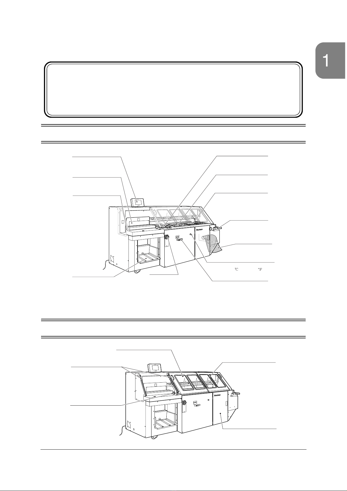
1-3 Parts Descriptions .................................................................................................. 2
1-3-1 Carriage Clamp Section ........................................................................................... 2
1-3-2 Level Plate Section................................................................................................... 2
1-3-3 Milling Section .......................................................................................................... 3
1-3-4 Melt Tank Section..................................................................................................... 4
1-3-5 Nipping Section ........................................................................................................ 5
1-3-6 Cover Feed Section.................................................................................................. 6
1-3-7 Delivery Section ....................................................................................................... 7
1-3-8 Touch Screen ........................................................................................................... 7
1-4 Screen Descriptions ............................................................................................... 8
2. Job Settings on Touch Screen ................................................................... 9
2-1 Entering the Job Information Using the Setting Screens ....................................... 9
Binding Mode Screen ...................................................................................................... 10
Start Mode Screen............................................................................................................ 11
Book Block Size Screen .................................................................................................. 12
Cover Sheet Size Screen ................................................................................................ 13
Function Screen............................................................................................................... 14
Milling and Nipping Screen ............................................................................................... 15
Gluing Screen Part 1 ....................................................................................................... 16
Gluing Screen Part 2 ....................................................................................................... 16
Gluing Screen Part 3 ....................................................................................................... 17
Gluing Screen Part 4 ....................................................................................................... 17
2-2 Bind the Books Using the Binding Screens.......................................................... 18
Binding Screens............................................................................................................... 19
2-3 Test Milling and Gluing..........................................................................................20
Test Milling and Gluing Screen........................................................................................ 20
2-4 Fine Adjustment .................................................................................................... 21
Clamp and Milling Fine-Adjust Screen............................................................................. 21
Glue Fine-Adjust Screen Part 1 ....................................................................................... 22
Glue Fine-Adjust Screen Part 2 ....................................................................................... 22
Glue Fine-Adjust Screen Part 3 ....................................................................................... 23
Nipping Fine-Adjust Screen ............................................................................................. 24
Scoring Fine-Adjust Screen ............................................................................................. 25
Cover Sheet Fine-Adjust Screen Part 1........................................................................... 26
Cover Sheet Fine-Adjust Screen Part 2........................................................................... 27
Cover Sheet Fine-Adjust Screen Part 3........................................................................... 27
Cover Sheet Fine-Adjust Screen Part 4........................................................................... 28
Cover Sheet Fine-Adjust Screen Part 5........................................................................... 28
2-5 Saving or Recalling or Deleting Job Settings. ...................................................... 29
2-6 Using the Single Operation Screen...................................................................... 30
Single Operation Screen Part 1 ....................................................................................... 30
Single Operation Screen Part 2 ....................................................................................... 31
Single Operation Screen Part 3 ....................................................................................... 31
Home Positioning Screens .............................................................................................. 32
Milling Brake Release Screen.......................................................................................... 32
2-7 Information Screen............................................................................................... 33

2-8 Error Screen......................................................................................................... 34
2-9 Numeric Keypad Screen ...................................................................................... 34
3. Starting the Binding Operation................................................................. 35
3-1 Turn On the Power Switch ................................................................................... 35
3-2 Safety Function Check ......................................................................................... 35
3-3 Enter the Job Information Using the Setting Screens .......................................... 36
3-4 Setting the Main Binding Screen.......................................................................... 40
3-5 Setting the Scoring Rollers................................................................................... 41
3-6 Setting the Scraper (For Padding Only) ................................................................43
3-7 Setting the Side Glue Rollers ............................................................................... 44
3-8 Start Binding......................................................................................................... 45
3-9 Adding More Cover Sheets .................................................................................. 47
3-10 Removing the Bound Booklets........................................................................... 48
3-11 Saving and Recalling the Job Information.......................................................... 49
3-12 Adding More Glue .............................................................................................. 52
3-13 Finishing the Binding Operation ......................................................................... 53
4. Parts Adjustments ..................................................................................... 55
4-1 Changing the Spine Glue Amount and Position................................................... 55
4-2 Adjusting the Side Glue Amount .......................................................................... 55
4-3 Changing the Nipping Setting .............................................................................. 56
4-4 Changing the Cover Feeding Settings ................................................................. 57
4-5 Changing the Scoring Position............................................................................. 58
4-6 Changing the Carriage Clamp Opening and Milling Guide Width ........................ 58
4-7 Milling Depth Adjustment ..................................................................................... 59
4-8 Glue Temperature Adjustment ............................................................................. 61
4-9 Side Glue Amount Adjustment (Far Side) ............................................................ 62
4-10 Nipper Height Adjustment .................................................................................. 64
4-11 Nipper Angle Adjustment ................................................................................... 65
4-12 Cover Sheet Angle Adjustment .......................................................................... 66
4-13 Blower Air Adjustment........................................................................................ 67
4-14 Double Feed Stop Pad Height Adjustment ........................................................ 67
4-15 Feed Table Height Adjustment........................................................................... 68
4-16 Scoring Roller Pressure Adjustment .................................................................. 68
5. Maintenance ............................................................................................... 69
5-1 Cleaning the Book Block Path.............................................................................. 69
5-2 Cleaning the Sensors........................................................................................... 71
5-3 Lubrication............................................................................................................ 72
5-4 Book Support Plate Replacement ........................................................................ 73
5-5 Milling Cutter Replacement .................................................................................. 75
5-6 Roughening Cutter Replacement......................................................................... 78
5-7 Glue Replacement ............................................................................................... 81
5-8 Double Feed Stop Pad Replacement................................................................... 83
5-9 Transport Belt Replacement ................................................................................ 84
6. Troubleshooting......................................................................................... 85
6-1 Problems with Booklet Quality ............................................................................. 85
6-2 Error Codes.......................................................................................................... 90
6-3 If a Circuit Breaker Trips ...................................................................................... 94
6-4 If a Message Screen Appears.............................................................................. 95
7. Optional Device .......................................................................................... 97
7-1 Weekly Timer ....................................................................................................... 97

8. Installation ................................................................................................ 101
8-1 Installation .......................................................................................................... 101
8-2 Installation of Extractor (Option)..........................................................................104
8-3 Installation of Weekly Timer (Option) ................................................................. 106
9. Appendix................................................................................................... 109
9-1 Specifications ..................................................................................................... 109
9-2 Accessories........................................................................................................ 110
9-3 Consumable Parts.............................................................................................. 113
9-4 Option................................................................................................................. 114
9-5 Index ................................................................................................................... 115

1
1-1 Machine Description
1-2 Safety Functions
1. Machine Description
BQ-
270
PERFECT BINDER
Milling Section
Mills the book spine.
MeltTank Section
Applies glue to the book spine.
Nipping Section
Pastes the cover sheet on the
book spine and forms the spine.
Cover Feed Section
Feeds the cover sheet
to the nipping section.
Trimmings Bag
Collects the trimmings
.
GlueTemperature Adjusting Kno
b
Adjusts the glue temperature
from 120 to 180 (248 to 356 ).
Milling ON/OFF Lever
Turns the milling operation ON or
OFF.Turn the lever to the right
to select milling ON.
Turn to the left to select milling
OFF.
Delivery Section
Stacks the bound booklets
vertically.
Power Switch
Touch Screen
Used to input necessary
information and operate the
machine.
Carriage Clamp
Clamps the book block.
Level Plate
Registers the bottom of the
sheet block.
BQ-
270
PERFECT BINDER
Safety Cover (right)
The machine stops if
this cover is opened.
Lower Nipper Door
The machine stops if
this door is opened.
Safety Cover (left)
Area Sensors
The machine stops if
this cover is opened.
The machine stops if
this light between the
sensors are cut.
E
mergency Stop Button
T
he machine stops if
t
his button is pressed.

2
1-3 Parts Descriptions
1-3-1 Carriage Clamp Section
1-3-2 Level Plate Section
Emergency Stop Button
Press this button to stop
the machine.
Turn the button clockwis
e
to release the emergenc
y
stop.
Book Block Insert Section
Insert the book blocks
here, aligning to the right.
Start Buttons
When using the manual starting mode, press
both buttons to start the binding operation.
Grease Nipples
Lubricate with
grease here.
BQ-
270
PERFECT BINDER
Delivery Section
Each booklet is delivered here.
Level Plate
T
he level plate moves forward to hold
e
ach book block as it is inserted.
I
t moves back when delivering the
b
ooklet.
Level Plate Slide Guide
Regularly lubricate with greas
e.

3
1-3 Parts Descriptions
1-3-3 Milling Section
Milling Select Lever
When milling the book spine,
this lever is used to turn the milling
operation ON or OFF.Set the lever
to the left to turn off the milling operation.
Front Milling Guide
This guide holds the book spine
while the milling operation is done.
Guide Block
This block transports the power
from the motor to the front milling
guide.
Brake Release Button
This button is used when
replacing the milling cutter.
This button works only after
pressing the brake release
button onTouch Panel Scree
n.
U
pper Knife
This guide holds the book
spine while the milling
operation is done.
Rear Milling Guide
WARNING
BQ-
270
PERFECT BINDER

4
1-3 Parts Descriptions
1-3-4 Melt Tank Section
BQ-
270
PERFECT BINDER
0
Adjust according to the glue
amount applied here.
Wiper 2
Glue Level Upper Limit
Keep the glue level lower
than this line.
The lower limit of the glue leve
l
is 8 mm (0.31") lower position
below the upper limit line.
Wiper 1
The distance of glue penetration
into the spine depends on the wiper
opening.
Application Drum 1
This drum is used to provide the
glue that penetrates into the spine.
Side Glue Roller
This drum is used to apply the glue
on the lower side of the book block.
Glue Temperature Adjusting Knob
The glue temperature can be adjusted from
120 to 180 . (248 to 356 )
Scrape Roller
This roller scrapes the extra
glue off of the spine.
Glue Supply Section
Add more glue here when
the glue level is low.
Lubrication Point
Refer to [5-3] for details.
Application Drum 2
Glue Amount Adjusting Plate
If too little glue is applied to the
side glue roller, or too much glue is
applied, adjust the glue amount by
moving this plate.
This plate is used to adjust the position of the side
glue roller on the far side of the machine. Turn the
plate counterclockwise, and the roller moves
forward to approach to the book block. (Normally
set to 0.)
This drum is used to put the
glue on the book spine.
Positioning Plate - Side Glue Roller (far side)
CAUTION
Do not touch the melt tank after the power is turned on.
The melt tank is heated to 200 degrees Celsius (400
Fahrenheit) and may cause severe skin burn.

5
1-3 Parts Descriptions
1-3-5 Nipping Section
BQ-
270
PERFECT BINDER
Rear Jog Guide
This forms the book
spine with the front
nipper.
Front Nipper
Rear Nipper
Front Jog Guide
Before the cover sheet is fed, the side
guide waits 3 mm (0.12") away from the
edge of the sheet. It registers the cover
with the rear side guide before the nipping
operation.
Before the cover sheet
is fed, the side guide
waits 3 mm (0.12") away
from the edge of the sheet.
It registers the cover with the
front side guide before the
nipping operation.
Nipper Angle Adjusting Block
Refer to [4-11] for details.
Registration Stopper
Angle Adjusting Lever
This lever is used to adjust
the cover sheet angle.
Refer to [4-12] for details.
Nipper Height Adjusting Ring
This ring is used to adjust the
book spine sharpness.
Refer to [4-10] for details.
Transport Belts
Transport the cover sheets.
Upper Cover Guide
Set to match the
cover sheet size.
Registration Stopper
Registers the cover
sheets to the right.

6
1-3 Parts Descriptions
1-3-6 Cover Feed Section
FeedTable Height
Adjusting Knob
Adjusts the height to
feed the cover sheet.
Cover Sheet Detect
Sensor on FeedTabl
e
Detects the cover sheet
s
on the feed table.
End Guide
FeedTable
Positioning Guide
Pad Height Adjusting Lever
This adjusts the height of the double
feed stop pads.If the pad is worn or
double feeding occurs
frequently, raise the pads.
Refer to [4-14] for details.
Fixed Scoring Roller
Scoring Roller Pressure
Adjusting Knob
Adjust to produce the
correct scoring line.
Adjustable Scoring Roller
Transport Roller
Feed Rotor
This feeds the cover sheets
using suction and friction.
Double Feed Stop Pads
Double Feed
Detect Sensor
This detects double
feeding by measuring
the light that penetrates
the sheet.
Blower Air Adjusting Lever
Refer to [4-13] for details.

7
1-3 Parts Descriptions
1-3-7 Delivery Section
1-3-8 Touch Screen
P
ush Plate
This plate pushes the
delivered booklets forward.
Stopper
Set this stopper next to the push
plate. The stopper will be pushed
forward as the booklets are stacked.
BQ-270
Touch Screen
Refer to Section 2 for details o
n
the screens.

8
1-4 Screen Descriptions
The BQ-270 has five kinds of screens. Refer to Section 2 [Job Settings on Touch Panel] for details. (See page 9.)
Function Setting Screen
Service Screen
These screens are used to display the current
job information during the binding operation.
The can also be used to make fine
adjustments. Refer to [2-2].
These screens are used to input the
necessary job information. Refer to [
2-1]. This screen is used to save or recall the
job settings. Refer to [2-5].
These screens are used during maintenance
(cleaning or parts replacement). They can also
be used to check the function of each section.
Refer to [2-6].
This screen is used to show the
ROM version
and the total binding number. Refer to [2-7].
Binding Screens
Setting Screens Memory Screen
Single Operation Screens
Information Screen
This screen is used to select the table
movement when the double feeding occurs,
milling function, and the delivery section full
detection ON/OFF.

9
2-1 Entering the Job Information Using the Setting Screens
Input the necessary job information such as the binding type, sheet size and other
functions. The Setting Screen can cover the following seven functions:
Setting Screens
2. Job Settings on Touch Screen
Press the box, and the Numeric Keypad
Screen appears.Input the setting value
on the Numeric Keypad Screen in
increments of 0.1mm (0.004").
1
2
3
4
5
6
7
8
9
10
Binding Mode Screen
Start Mode Screen
Book Block Size Screen
Cover Sheet Size Scree
n
Function Screen
Milling, Nipping Screen
Gluing Screen Part 1
Gluing Screen Part 2
Gluing Screen Part 3
Gluing Screen Part 4
P. 1
P. 2
P. 3
P. 4

10
2-1 Entering the Job Information Using the Setting Screens
- - Binding Mode Screen
: Binding with cover sheets.
Select when binding with cover sheets.
When this button is selected, the side glue rollers should be moved into their working
positions. Refer to [3-6] on page 44. The side glue roller on the near side is controlled
by the computer. The side glue roller on the far side must be set manually.
: Binding without cover sheets.
Select when binding without cover sheets.
When this button is selected, the side glue rollers should be moved out of their work-
ing positions. Refer to [3-6] on page 44. The side glue roller on the near side is con-
trolled by the computer. The side glue roller on the far side must be set manually.
Also, when this button is selected, the support plate should be installed. Refer to [3-3]
on page 36.
OK button. Each of the Setting Screens has an OK button. Press this button to input
the setting and go to the next screen.
1
12
3
1
2
3

11
2-1 Entering the Job Information Using the Setting Screens
- - Start Mode Screen
Return to the home position during every changeover. Normally, select .
: Each part of the machine goes back to the home position before moving to
a new set position.
: Each part of the machine moves to the set position directly.
Select the start mode.
: Normal Start mode. Binding operation starts with start buttons.
: Auto Start mode. Binding operation starts after the time set in .
Start waiting time
Input the time after the book block is inserted into the carriage clamp till the bind-
ing operation starts in increments of 0.1. Input range is 0.0 to 9.9.
2
1
2
3
1
2
3
3

12
2-1 Entering the Job Information Using the Setting Screens
- Book Block Size Screen
Input the book block thickness. Measure the actual book block thickness using the
attached caliper and input the value. The input range is 0.3 to 50 mm (0.010” to
2.000”).
Input the book block length. Measure the actual book block length and input the
value. The input range is 135.0 to 320.0 mm (5.315” to 12.600”).
3
1
2
1
2

13
2-1 Entering the Job Information Using the Setting Screens
- - Cover Sheet Size Screen
Input the cover sheet length in increments of 0.1 mm (0.005”). The input range is
230.0 to 660.0 mm (9.055” to 25.985”).
Input this setting first on this screen.
Input the length between the cover sheet rear edge and the spine (using either
edge, or the center of the spine). The input range is shown in illustration below.
or : Either edge of the spine
: Center of the spine.
Input the cover sheet width in increments of 0.1 mm (0.005”). The input range is
135.0 to 320.0 mm (5.315” to 12.600”).
When measuring the distance to the center of the spine, use the accessory
alignment plate.
4
1
2
3
1
2
135 to 320
(5.32" to 12.60")
230 to 660
(9.05" to 25.98")
120 to 350
(4.72" to 13.77")
110 to 310
(4.33" to 12.20)
Movable Side
Scoring
(Front Side)
Downstream
Fixed Side
Scoring
(Rear Side)
If the dimension is out of this range, the front
or rear guides may not reachthe cover sheet edge.
mm(inch)
3
01234567891234567891234
5
10 20
think automation.
think automation.
think automation.
Center of the Spine
Alignment Plate

14
2-1 Entering the Job Information Using the Setting Screens
- - Function Screen
(ON): Use the double feed detecting function.
(OFF): Do not use the double feed detecting function.
If the machine produces false indications of double-feeding because of an
image on the cover sheet, turn this function OFF.
5
1
1
Table of contents
Other Horizon Fitness Binding Machine manuals