3
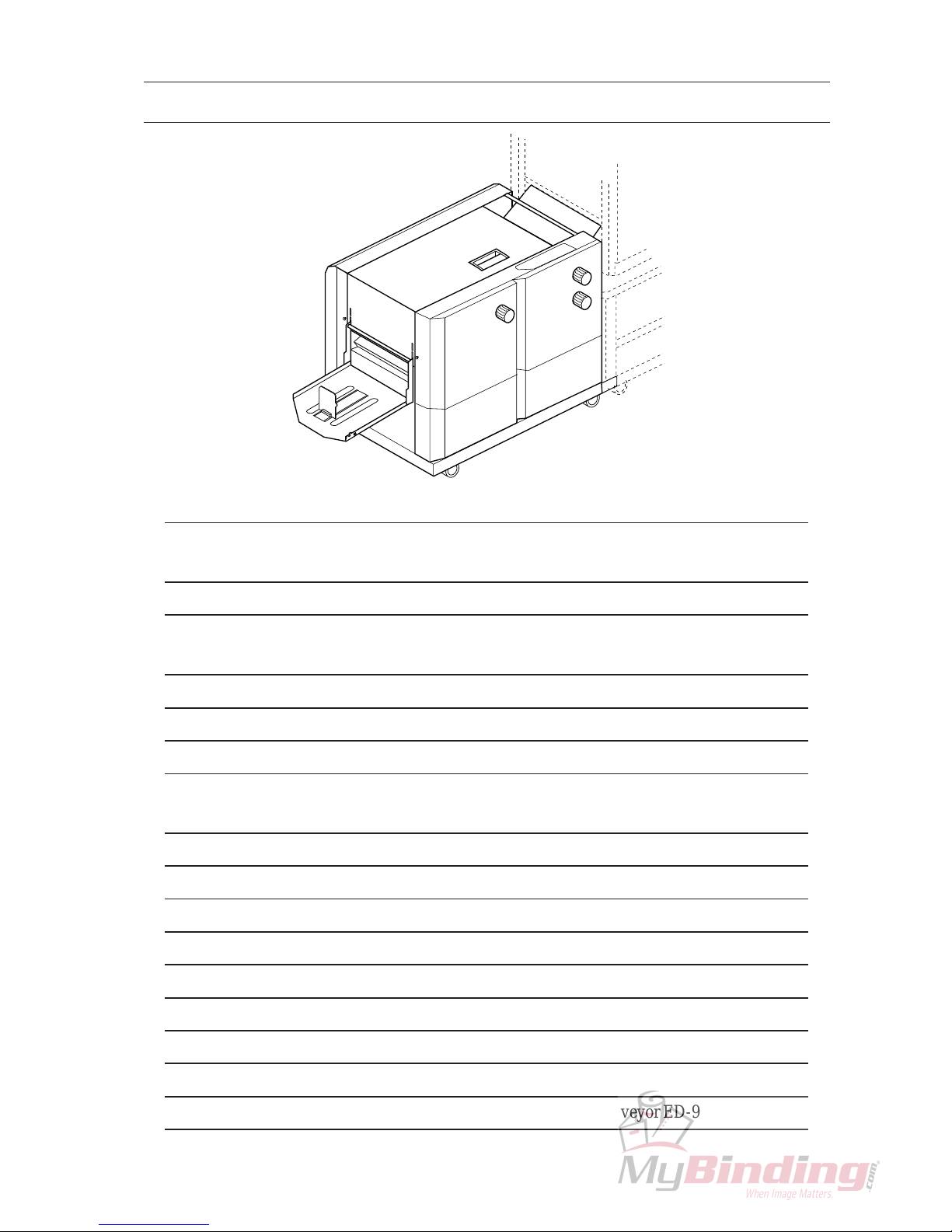
2. Operation Overview
2-1 SPF-9
Connecting cable on SPF-9 is connected to collator.
1. Turn on power switch on SPF-9.
On operation panel,
- automatic mode lamp will illuminate.
- stapling & folding lamp will illuminate.
2. Turn on power switch on collator.
3. Pile sheets into collator and set required set up on SPF-9 following "2-1 Operation Procedure"
procedure 5 to 20 (page15 to 18) in SPF-9 Operation Manual.
4. Select automatic mode with function mode select button.
5. Press start button on collator.
- Sheets delivered from collator will be stapled automatically.
6. Press stop button on collator to stop SPF-9.
SPF-9 will stop without pressing stop button in the following cases.
- Sheet jam, misfeed, and double feed occur in collator. Collator lamp on SPF-9 illuminates.
- Sheets are jammed in SPF-9. Sheet jam lamp on SPF-9 illuminates.
- Sheet jam, misfeed and double feed occur
in collator.
- Sheets are jammed in SPF-9.
- Sheets are jammed in FC-9.
- Upper knife stops at the middle of cutting
process.
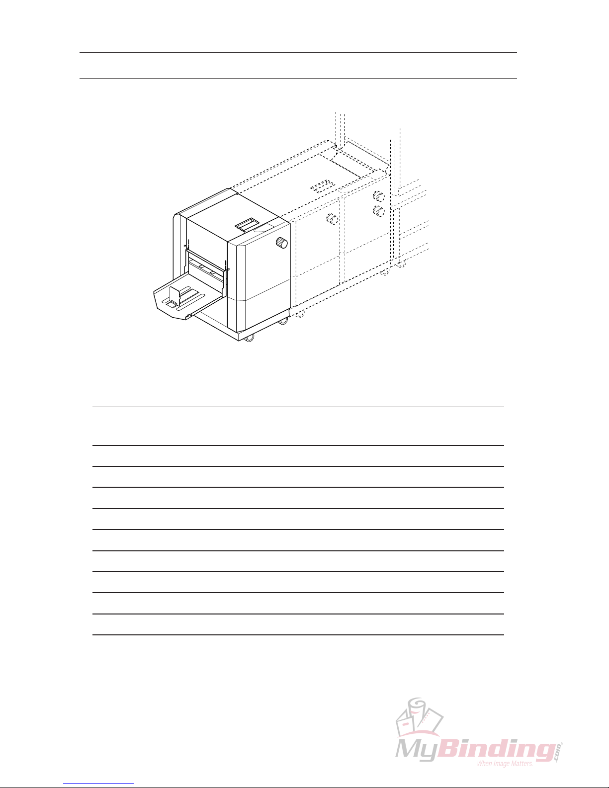
Cable on FC-9 is connected to SPF-9.
1. Turn on power switch on SPF-9.
2. Turn on power switch on collator.
3. Pile sheets into collator and set required set up on SPF-9 and FC-9 following "2-1 Operation
Procedure" 5 to 20 (page 15 to 18) in SPF-9/FC-9 Operation Manual.
4. Select automatic mode with function mode select button.
5. Press start button on collator.
- Sheet delivered from collator will be stapled and folded in SPF-9 and be cut in FC-9 auto-
matically.
6. Press stop button on collator to stop SPF-9.
SPF-9 will stop without pressing stop button in the following cases.
- Collator lamp in SPF-9 will illuminate.
- Sheet jam lamp on SPF-9 will illuminate.
- Jam lamp will illuminate.
- Knife lock lamp will illuminate.
2-2 FC-9