iii
iii
DETAIL ICON REFERENCE KEY
HARDWARE
Cap Head Screw Flat Head 1 Flat Head 2 Button Head
Setscrew Ball Bearings 1 Ball Bearings 2
Pins
Washers Shims Retaining Clips
Nuts (Lock/Plain)
INTRO
Intro to the 8IGHT 2.0™EU Manual
STEP I-01
q
8IGHT 2.0EU COMPLETED KIT SPECIFICATIONS
Body Clip (A8200)
2-56 x 1/4" (A6232)
2-56 x 1/2" (A6254)
4-40 x 1/2" (A6204)
4-40 x 3/8" (A6206)
4-40 x 5/8" (A6221)
5-40 x 7/8" w/ 5/8" Shoulder (A4414)
4-40 x 1/4" (A6234)
4-40 x 1/2" (A6256)
5-40 x 3/8" (A6277)
5-40 x 1/2" (A6278)
2-56 x 1/4" (A6255)
5-40 x 3/4" (A6279)
5-40 x 20mm (A6281)
5-40 x 1" (A6280)
5-40 x 3/8" (A6270)
5-40 x 1/2" (A6271)
5-40 x 3/4" (A6272)
5-40 x 5/8" (A6275)
5-40 x 7/8" (A6273)
5-40 x 1-7/8" (A6273)
8-32 x 3/8" (A6264)
8-32 x 1/2" (A6262)
F 5-40 x 1/8" (A6228)
C 4-40 x 1/8" (A6227)
C 5-40 x 3/16" (A6299)
C 8-32 x 1/8" (A6298)
F 5-40 x 1/8" (A6297)
F 8-32 x 1/8" (A6296)
O10-32 x 3/8" (A6295)
5-40 x 22mm (A6045)
6x10x3mm (A6946)
5x11x4mm (A6947)
F 5x11x4mm (A6948)
5x10x4mm (A6949)
1/2” x 3/4" (A6953)
8x14x4mm (A6945)
5x13x4mm (A6949)
Ball Stud (A6215)
#4 x .030" (A6350)
.250 x .094 x .020" (A9166)
#5-40 (A6302)
3 x 8mm (A9106)
3 x 12mm (A3500)
#4-40 (Mini) (A6306)
#8-32 (A6311)
2.5 x14mm (A3518)
2.5 x 12.37mm (A3518)
3 x 17mm (A3518)
2.5 x 12.8mm (A3518)
4 x 66mm (A6500)
3.5 x 53mm (A6503)
5x7x.2mm (A6356)
6x11x.2mm (A3501)
14x17x.1mm (A4452)
14x17x.25mm (A4452)
5mm E-clip (A6109)
5-40 x 1/2" (A6240)
8-32 x 3/4" (A6263)
5-40 x 20mm (A6284)
Left Hand Thread
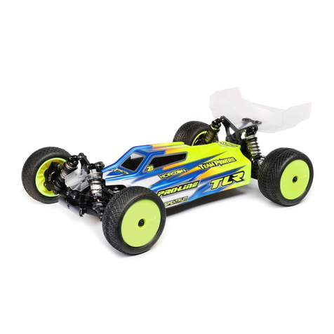
Thank you for selecting the Team Losi Racing 8IGHT 2.0EU as your new racing buggy. The 8IGHT 2.0 platform has already distinguished itself as a
top caliber racing chassis. As you will see, we have made every eort to produce a vehicle that is not only the most competitive but also easy to main-
tain. The simple bag-by-bag assembly sequence and easily followed instructions with drawings combined with Team Losi Racing's world famous quality
tting parts will make using the 8IGHT 2.0EU a most enjoyable vehicle.
Before you open the rst bag, please take a moment to read through the following instructions. This will familiarize you with the various parts,
assembly tips and descriptions as well as the tools needed. This will also help you understand the dynamics of the 8IGHT 2.0EU and setup tips to ensure
the best possible experience.
Good luck and good racing,
Team Losi Racing
Welcome Team Losi Racing 8IGHT 2.0EU Owner!
Vehicle/Manual Organization:
The vehicle is composed of dierent steps marked A through H. Each bag
contains all of the parts necessary to complete a particular section of the
vehicle. Some of these bags have sub-assembly steps within them. You
should read through the instructions for an entire bag prior to working
on your vehicle. Next to each of the step numbers is a check box. At the
completion of each step, place a check in this box so that if you must
stop and come back to the assembly, you can begin where you left o.
For your convenience, an actual-size Hardware Identication Guide is
included as a fold-out page at the back of this manual. Hardware that is
not easily dierentiable in each step is called out with an icon which
contains a small picture of the part genre (referenced on the Hardware
Identication Guide), the quantity of that part required for what is shown
in the step, and the size or name of that part. To check a part, hold it
against the silhouette until the correct part is identied. Associated
with each of these parts, in the
Hardware Identication Guide, is
an LOSA Number which is used
when ordering replacement
parts for your 8IGHT 2.0EU. In
some cases, extra hardware has
been supplied for parts that may
be easy to lose.
You can identify components used in each step by their LOSA Number
and component name. With the exception of a few parts, these are not
referenced in the Hardware Identication Guide.
The molded parts in Team Losi Racing vehicles are manufactured to
demanding tolerances. When screws are tightened to the point of
being snug, the parts are held rmly in place. For this reason, it is very
important that screws not be over-tightened in any of the plastic parts.
In some steps there will be a lled black circle with a white number.
These indicate the specic order by which assembly must occur. In cases
where steps are repeated (front/rear or left/right) these numbers may
be omitted. Please note these numbers do not call out every sub-step
required for the step’s assembly procedures, they only highlight the
critical order required for assembly.
In each step,“Detail Icons”( ) call out critical precautions or assembly
tips for the process. There is a reference key that describes the meaning
of each of the icons located on the fold-out Hardware Identication
Guide at the back of this manual. To ensure that parts are not lost during
construction, you should work over a towel or mat to prevent parts from
rolling away.
IMPORTANT SAFETY NOTES:
1. Select an area for assembly that is away from the reach of small
children. Some parts in this vehicle are small and can be swallowed
by children, causing choking and possible internal injury; PLEASE USE
CAUTION!
2. The shock uid and greases supplied should be kept out of
children’s reach. They are not intended for human consumption!
3. Exercise care when using any hand tools, sharp instruments, or
power tools during construction.
4. Carefully read all manufacturer’s warnings and cautions for any
chemicals, glues, or paints that may be used for assembly and
operating purposes.
Age Recommendation: 14 years or over. This is not a toy. This product
is not intended for use by children without direct adult supervision.
Note: Final vehicle weight will vary depending on accessories used.
*All measurements taken at ride height 32mm.
Overall Chassis Length: 415mm Wheelbase: 323-327mm *Front Track Width: 308mm
Overall Length w/Tires: 497mm *Overall Height: 168mm *Rear Track Width: 308mm
Table 1: 8IGHT 2.0EU Completed Vehicle Specications.
6
5
4
Front:
Standard Smart
Spring Wire Dia:
Qty of Springs:
Ramp Plate:
Grease:
Diff Fluid:
Center:
Standard Smart
Spring Wire Dia:
Qty of Springs:
Ramp Plate:
Grease:
Diff Fluid:
Differentials
GLUE
Apply CA Glue
Pay Special
Attention
CUT
Cut/Trim Ensure Free
Movement
Ensure Free
Rotation
Ensure Proper
Orientation Push Firm
Tighten
L
R
L
R
Assemble
Other
Side the Same
LSide
Shown x2 Repeat/Build
Multiple Screw Partially
DO NOT
Over -Tighten/
Snug Tight
1
These numbers are used to identify the critical order in which assembly must occur. *Note: They will not call out every stage of the assembly process.
Apply Losi-Lok™
GREASE
CLEAR
Apply High
Pressure Black
Grease
Degrease with
Motor Spray
OIL
Fill With
Silicone Oil Pre-Tap
LOSI-LOK
Register your Losi Product Online:
Register your 8IGHT 2.0EU now and be the rst to nd out about the latest options parts, product updates and more. Log on to www.LOSI.com
and follow the product registration link to stay connected.
