10
System Features®
The Horizon Signal system is capable of three communication types:
• Radio - Wireless communication between all controllers in the system.
• Cable - Wired communication between all controllers in the system.
• Quartz - Synchronized timing of all controllers in the system via quartz clocks. Controllers do not communicate
in this mode. NOT RECOMMENDED.
• A system can also utilize a mixture of radio and cable connections.
Systems can include up to 14 controllers or phases of traic. Multiple controllers can be grouped into the same traic
phase.
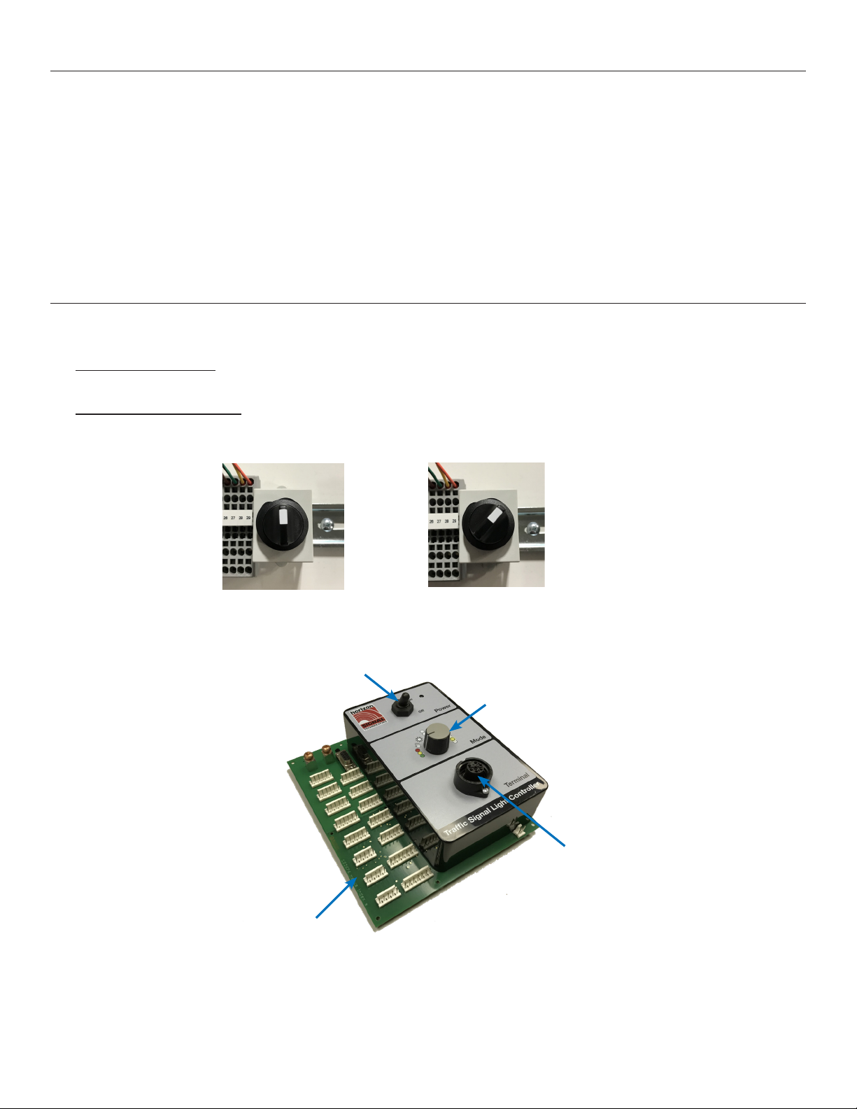
Multi-Signal 2.0 Controller
The Multi-Signal 2.0 Controller is capable of two Operation modes, changeable via the Operation Selector Switch inside the
SQ3TS control cabinet:
1. Enhanced Operation - Utilizes all features of the MS 2.0 Controller. Each signal unit must have a MS 2.0 controller
installed. To activate Enhanced Mode, power on the controller with the Mode Selector in the upward position.
2. Compatibility Operation - Allows MS 2.0 Controllers to work in conjunciton with MS 1.0 controllers. See Page 21 for
more information on how to enable this mode. To activate Compatibility Mode, power on the controller with the Mode
Selector in the right position.
The controller is programmed using the PTS Programmer handheld module. The programmer plugs into the face of the
controller via the 7-pin recept indicated below.
The Rotary Switch can be used to quickly switch between Automatic, Manual, and Flashing operation. Turn the dial to select
the desired setting, and al lother signals in the system will enter that mode. The dial only has to be set on one controller.
There is no need to set the dials to the same Mode on all trailers.
Circuit Board
PTS Programmer recept
(Hirschmann)
Power Switch
Rotary Switch
Enhanced Operation Compatibility Operation