Horizont HLPK 15 LED User manual

horizont group gmbh
Traffic Safety
Postfach 13 40
34483 Korbach
Homberger Weg 4
-
6
34497 Korbach
Germany
Telefon: +49 (0) 56 31 / 5 65
-
2 00
Telefax: +49 (0) 56 31 / 5 65
-
2 48
traffi[email protected]
www.horizont.com
Collapsible light arrow
86274-15 (EN)
E - 09/2021
Light arrow HLPK 15 LED
Light arrow HLPK 13 LED
Light arrow HLK 9 LED
Vertical lift HLPK 15 LED
Operating Instructions
Vertical lift light arrow
Light arrow / Light cross
(HLPK 9 LED)

2 3
Original manual
Light arrow / Vertical lift light arrow HLPK 15 LED, HLPK 13 LED, HLK 9 LED
Safety instructions ..................................................................................................... 02
Regular maintenance .................................................................................................. 07
Short product description ............................................................................................ 08
Technical data ............................................................................................................ 08
Operation .................................................................................................................... 09
Remote control .......................................................................................................... 09
Features ..................................................................................................................... 11
Spare part list ............................................................................................................. 14
Optional accessories (remote controls) ........................................................................ 16
Wiring diagram ........................................................................................................... 18
Autodiagnosis of the main controller and the complete system ................................... 20
Troubleshooting .......................................................................................................... 21
Operation without MS340 LED auxiliary lamps ............................................................ 22
Operation with rotating arrow ..................................................................................... 22
Connection diagrams ................................................................................................. 23
Electromotive lifting and lowering device .................................................................... 24
Adjusting the proximity switches ................................................................................. 25
Mounting on roof racks ............................................................................................... 25
Mounting on flatbed vehicles ...................................................................................... 26
Different lifting devices .............................................................................................. 27
Connection sequence of the lamps ............................................................................. 30
Wiring diagram housing ............................................................................................. 32
Short Description „
Cradle for the remote control
-
drilling plan and installation
“ ................ 33
Safety instructions
Before carrying out any work on the device it has to be switched off!
General information on the user manual
This operating instruction provides important information on how to work with the device.
All technical information in this manual has been compiled with the utmost of care. We can, however, not ex-
clude discrepancies or mistakes and do therefore neither assume warranty nor any legal liability nor liability
for any consequential damages due to incorrect information.
We highly appreciate any information on possible mistakes or discrepancies!
The basic prerequisite for safe working is compliance with all safety and handling instructions stated in this
manual.
Furthermore, the local accident prevention as well as safety regulations have to be observed.
The operating instructions must be read carefully before starting any work!
It is part of the product and must be kept in safe place in the immediate vicinity of the device, accessible at
any time for the personnel.
If you sell or distribute this product, make sure to also hand out this manual.
For better visualization, the illustrations in this manual are not necessarily true to scale and
may differ from the actual design.
General safety instructions
Meaning of pictograms
Safety notes are characterised by pictograms.
Additionally they are preluded by signal words, expressing the scale of the hazard.
• Safety Instructions must be duly observed under all circumstances!
• Always act cautiously in order to avoid accidents, personal injuries and damage to property!
Warning!
Indicates a potentially dangerous situation which can result in death or severe injuries if
not being avoided.
Caution!
Indicates a potentially dangerous situation, which may lead to minor or light injuries if not
being avoided.
Caution!
Indicates a potentially hazardous situation that may result in property damage if not being
avoided
Hints and recommendations
NOTE!
Highlights useful hints and recommendations as well as information for an efficient and
trouble-free operation.
Limitation of liability
All information and instructions in this manual were compiled under consideration of all valid and applicable
standards and regulations, our state of the art technique as well as our long-term experience and knowledge.
The manufacturer assumes no liability for damage due to:
• Non-observance of the operation and maintenance instructions
• Improper / unintended use
• Deployment of non-trained personnel
• Unauthorized conversions
• Technical changes
• Use of non – approved / unauthorized spare and wear parts
In case of ordering customized versions, use of additional options or due to state of the art technical alterations
the actual scope of supply may differ from the explanations and illustrations described in this manual.
Additionally the responsibilities agreed upon in the delivery contract, the general terms and conditions as well
as the manufacturer’s conditions of delivery and the statutory provisions valid at the time of contract conclu-
sion shall apply.
4 5
Warranty
Wear parts are all components having direct contact with the material processed by the machine. These com-
ponents are excluded from warranty and defect claims provided it is wear.
Warranty
The manufacturer guarantees the functional capability of the process technology used and the stated perfor-
mance parameters. The warranty period begins at the time of acceptance without defects.
Warranty
The individual warranty conditions can be found in the sales contract
.
In general rules:
In case of conversions or technical modifications which were not certified by horizont group gmbh, any war-
ranty claims expire.
Repairs to the towing device of the vehicle may only be carried out by certified workshops or the manufacturer
itself.
Spareparts
Warning!
Incorrect or faulty replacement parts may lead to damages, malfunctions or even total
breakdown of the device, thus severely affecting the safety.
Always use original spare parts only!
Original spare parts can be obtained directly from the manufacturer.
Customer service
In case you need any technical information or advise, our customer service is at your disposal.
Furthermore our employees always appreciate receiving feedback from the user - such as experiences arising
during the application - in order to constantly work on improving our products.
Copyright
This manual is intended exclusively for persons working with the unit. This manual may not be passed on to
third parties without the written consent of the manufacturer.
In case you need any technical information or advise, our customer service is at your disposal.
Furthermore our employees always appreciate receiving feedback from the user - such as experiences arising
during the application - in order to constantly work on improving our products.
NOTE!
Any content of this instruction like texts, drawings, pictures and other representations are pro-
tected by copyright law and subject to industrial property rights. Any improper use is punishable.
Reproduction in any form - even in extracts - as well as the utilization and / or communication
of the contents are not permitted without written consent of the manufacturer. Violations require
compensation. Further claims remain reserved.
Safety
This section gives an overview of all important safety aspects for optimum protection of personnel and for a
safe and trouble-free operation. Failure to comply with the safety instructions stated in this manual may lead
to considerably hazardous situation.
Responsibility of the operator
The operator of the device is subject to the legal obligations for safety at work.
In addition to the safety instructions in this manual the safety standards, accident prevention as well as envi-
ronment protection regulations on site have to be adhered to.
It is essential that the operator
• is informed about the applicable health and safety regulations on site.
• identifies additional hazards which might arise due to special working conditions at the operation site by
means of a risk assessment.
• implements the necessary rules of conduct stated in the user manual at the operation site.
• check at regular intervals during the machine‘s entire period of use whether the user instructions corre-
spond to the current state of rules.
• clearly regulates the responsibilities for installing, operating, maintaining and cleaning the device.
• ensures that all employees working on or with the machine have read and understood the operating
instructions. In addition he must at regular intervals train the employees in how to deal with the machine
and inform them about potential hazards.
In addition, it is the operator‘s responsibility to ensure that:
• the machine is always in a technically perfect condition.
• the machine is maintained in accordance with specified maintenance intervals.
• all safety equipment is regularly checked for completeness and correct functioning.
• the required inspections are carried out or arranged to be carried out at a self-defined or predefined time
interval.
Staff requirements
Qualification
WARNING!
Inappropriate handling can lead to considerable personal injury and property damage. All activities
should only be carried out by qualified personnel.
Hazards
The following section lists residual risks that were determined on the basis of a hazard analysis.
The hazard notes listed here and the safety instructions in the previous sections of this manual must strictly
be observed to reduce possible health hazards and to avoid dangerous situations.

6 7
Electrical current
DANGER!
Touching live parts is an immediate risk of fatal injury. Damage to the insulation or individual
components can be potentially life-threatening.
Repairs to the electrical system of the device may only be carried out by qualified electricians!
Before carrying out any work on the device, first disconnect the negative terminal and then the positive
terminal on the rechargeable batteries.
Batteries & rechargeable batteries
WARNING!
Improper handling of batteries or rechargeable batteries may release toxic substances or even lead
to their explosion.
During the charging process, explosive gas mixtures can originate. Therefore
- you may not smoke
- you must avoid sparking and ensure adequate ventilation
- you may not use any flammable cleaning agents in the immediate vicinity of the batteries !
Adhere to the instructions of your manufacturer for rechargeable batteries!
Environmental protection
CAUTION!
Rechargeable batteries contain toxic heavy metals. They are hazardous waste and must be collected
and disposed of in accordance with the local applicable regulations. It is the owner‘s responsibility to
inform about disposal regulations and disposal centres.
Intended use of the product
WARNING!
Any use of the device beyond its intended use or any other use not in accordance with the inst-
ructions may lead to dangerous situations for which horizont group gmbh does not assume any
responsibility.
For this reason:
• you may only use the device for its intended purpose.
• you have to strictly follow all instructions in this manual. In particular, refrain from the fol-
lowing operations, which are deemed to be improper: modification, conversion or alteration
of the construction or individual equipment parts with the aim of altering the usability of
the device. Claims of any kind for damage resulting from improper use are excluded. The
operator alone is liable for all damage resulting from improper use.
WARNING!
Installation and operation of the light arrow on public roads may only be carried out in compliance
with the local applicable regulations (in Germany RSA, TL warning lights, StVO)!
WARNING!
During the process of lifting/ lowering of the light arrow no persons may be in the vicinity of the
light arrow. Furthermore, no objects may be transported in the area of the light arrow which obs-
truct, block or endanger the operation of the light arrow (vertical sliding arrow).
WARNING!
When switching off the light arrow via the remote control, the position of the rotating arrow re-
mains the same. It is not automatically turned to the centre (neutral) position
WARNING!
Driving into the flowing traffic with the light arrow
• when the light arrow is mounted fix to the rear of the vehicle, the maximum speed allowed is
150 km/h.
• when mounted on a lifting and lowering device, the maximum speed allowed is:
30 km/h in upright position,
150 km/h in lowered position (arrow on lifting/lowering frame)
• when properly mounted on a flatbed vehicle behind the driver‘s cab, the maximum speed allo-
wed is 80 km/h (vertical sliding frame).
CAUTION!
When operating the device on the vehicle’s electrical system, the electrical circuit must always be
protected accordingly.
Regular maintenance
Recharge the batteries after each use and check the acid level at regular intervals. If necessary,
re-fill with distilled water and pay particular attention to corrosion of the terminals.
Check the light arrow for visible damage.
We do not recommend cleaning the unit with high-pressure cleaners. Avoid chemical cleaning
agents.
In case the light arrow is not used for a longer period of time, disconnect the rechargeable battery
and check the charging level.
Store the unit in a dry place

8 9
Short product description
The light arrow is suitable for stationary and mobile use on motorways, expressways, federal and rural roads
as well as in inner-city areas. The locally applicable regulations must be observed:
in Germany RSA, TL warning lights, StVO.
The light arrow is equipped with LED lamps. It is available in three versions depending on the construction: with
electric lifting, manual lifting or fixed mounting.
Operation is done via an external remote control. The device can be used universally in 12Volt or 24V on-board
networks. LED lamp monitoring, night reduction of the lamps and deep discharge protection are integrated.
The lamp monitoring indicates a failure in the signal image, depending on the fault, by the yellow or red LED
lighting up in the remote control.
The dimming reduces the luminosity of the LED lamps depending on the ambient luminosity (to protect mo-
torists from dazzling).
The deep discharge protection switches the device off once the battery is discharged (battery protection).
The main control is located in the control box. All electrical connections are spring connected to the main
control, with the exception of the lifting actuator and power supply.
The circuit board can be removed after loosening the fixing screws, removing the spring connectors, loosening
the motor cables and supply cable.
Technical Data
Nominal operating voltage ..........................................................................................12/24 V
Max. operating volltage ..............................................................................................30 VDC
Min. operating voltage ................................................................................................10 VDC
Max. actuator current .................................................................................................10A
(temporarily at lifting / lowering actuator)
Light ducts .................................................................................................................16
Outputs for additional lamps .......................................................................................2 (max. à 6 A)
Automatic switch – off light arrow (deep discharge protection) ................................... at 10 V
Provide fuses on the vehicle........................................................................................ min. 25 A
- automatic voltage adjustment of the actuators
- Night-time reduction of the LED lamps
- Reverse polarity protection
Radio remote control
Transmitting frequency ............................................................................................... 2,4 - 2,48 GHz
Transmission performance .......................................................................................... 10 mW
Operating hours of the system with 1 x 180 Ah / 12 V battery (approx. with completely charged battery)
Signals LEFT showing / RIGHT showing / CROSS Day Night
with mit LED – lamps 100 h 250 h
Operation
The entire operation is carried out by means of the remote control.
- Switch on the remote control
- If existing, release the locking lever of the board‘s lifting mechanism.
( This is only necessary in case of manual locking and electromotive uprighting )
- Select the desired function on the remote control.
- Green flashing, respectively green static light of the control LEDs indicates correct functioning of the
chosen feature on the remote control.
The LEFT ARROW, RIGHT ARROW and CROSS functions can only be activated when the board is fully upright.
On the remote control, the PANEL UP indicator must light up (except for fixed installation).
When the panel is only partially upright, only the auxiliary lamps, if fitted, are active.
Alternatively, the panel can be raised using the LEFT ARROW, RIGHT ARROW and CROSS keys. When the posi-
tion is reached, the selected light pattern is activated.
Remote control
www.horizont.com
The LEDs on the remote control are dimmed depending on the ambient light conditions. At a certain ambient
brightness the buttons (outline and symbols) are additionally illuminated.
ARROW LEFT (5)
CROSS (6)
ADDIONTAL MS340 LAMPS
(7)
SPECIAL
FEATURES
ARROW RIGHT (4)
PANEL UP (3)
PANEL DOWN (2)
ON / OFF (1)

10 11
BATTERY CONDITION INDICATION
green > 12,1 V ( > 45% )
yellow 12,1 V> Ubatt < 11,8V ( 20% - 45% )
red < 11,8 V ( 20% )
ERROR DISPLAY
red error indication
ACOUSTIC ERROR INDICATION
At mobile warning trailers, malfunctions will also be indicated by an acoustic signal.
WIRELESS (RADIO) REMOTE CONTROL
The radio remote control contains a high quality Ni-Mh battery.
As soon as the cable is connected, it is automatically charged via the internal charge controller.
The charging time of the empty battery is about two hours. During operation, the status of the
internal battery is displayed in intervals of approx. 10 seconds in the battery condition display.
This is indicated by flashing of the LED.
Flashing green: Remaining capacity <40 %
Flashing yellow: <20 %
Flashing red: <10 %
In addition, an acoustic warning signal is emitted by the remote control when reaching its low battery capacity.
Operating time with fully charged battery approx. 10 hours (continuous operation).
In radio mode, the remote control switches off after approx. 5 minutes.
In cable mode the remote control does not switch off.
When the cable is plugged in, there is no radio communication with the control unit !
CHARGING INDICATOR (RADIO) / OPERATING STATUS INDICATOR (CABLE)
When the charging cable or data cable is plugged into the remote control during radio operation (with the
remote control and main control switched off!), the LED at the ON/OFF button lights up yellow for approx. 30
minutes. This indicates that the remote control is supplied with power and the charging device is working.
Charging continues automatically even if the yellow LED turns off.
The charging indicator can be reactivated by pressing the ON/OFF button very briefly.
This is for information purposes only!
To switch on the control unit or the remote control in this state, press and hold the
ON/OFF key pressed (see description below).
If no connection can be established, the remote control switches off automatically after a few
seconds in radio operation and after approx. 5 minutes in cable operation.
The internal charging device allows charging between a temperature of +5 C° and +60 C.
This is a technical necessity in order to ensure the long service life and operational safety of the
internal battery. However, the yellow charging indicator continues to light up yellow beyond the
temperature range as described.
CAUTION!
The socket on the remote control must be closed with the supplied protective cap when the cable
is not plugged in.
Otherwise there is a risk of water penetrating the housing and damaging the electronics.
The bayonet lock must always be closed, even when the plug with cable is plugged in.
Features
SWITCH ON Press key for approx. 1 seconds .
LED indication ( 1 ):
green connection with main control was established successfully
red connection with the main control could not be established -
no communication or control system has switched off due to under voltage
SWITCH OFF press key for approx. 4 seconds until the LEDs of key 4 (arrow right ) and
key 5 (arrow left) light up in red colour. Release key
Working with the radio version, the arrow itself is also switched off provided a radio connection
is established. A working radio connection is indicated by the red LEDs (4) and (5). If there is no
radio connection, the LEDs light up yellow.

12 13
Arrow
left
Press key
the LED (5) flashes in the same frequency as the light arrow does
:
green all lamps work properly
yellow one lamp is defective or cable break or cable
interruption or short circuit
red two or more lamps are defective or cable break
or interruptiong
red flashing
Interruption or fault of the proximity switches of
the rotating arrow (rotating arrow is no longer in
its final position)
When using the light cross (HLK 9), the device will show
„Cross“automatically in this case.
CROSS
Press key ,
the LED (6) flashes in the same frequency as the light arrow does:
green all lamps work properly
yellow one lamp is defective or cable break or cable
interruption or short circuit
red two or more lamps are defective or
cable break or interruption
red flashing
Interruption or fault of the proximity switches
of the rotating arrow (rotating arrow is no longer
in its final position)
Arrow
right
Press key,
the LED (4) flashes in the same frequency as the light arrow does
:
green all lamps work properly
yellow one lamp is defective or cable break or cable
interruption or short circuit
red two or more lamps are defective or
cable break or interruption
red flashing
Interruption or fault of the proximity switches
of the rotating arrow (rotating arrow is no longer
in its final position)
When using the light cross (HLK 9), the device will show
„Cross“automatically in this case.
Additional
lamps
Press key,
The currently shown signal is switched off, only the additional lamps
(MS 340) keep flashing, The LED (7) flashes in the same frequency as
the light arrow does:
green all lamps work properly
red two or more lamps are defective or cable break or
interruption
LED off additional lamps are de-activated
When using additional lamps, you may only use horizont LED MS 340
lamps, which can work as halogen- imitating or flash- imitating lamps.
Lower board
Press key and keep pushed until the board has
reached its final position (dead man‘s switch),
board is lowered
LED ( 2 ):
Flashing green the lifting/lowering actuator is
active, end position not yet reached
Lit up green
final position is reached
Red flashing Error: Time exceeded or cable
interruption of sensor
Lift board
Press key and keep pushed until the board has
reached its final position (dead man‘s switch),
LED ( 3 ):
Flashing green the lifting/lowering actuator is
active, end position not yet reached
Lit up green
final position is reached
Red flashing Error: Time exceeded or cable
interruption of sensor
Press key: special features (such as work lamp, etc)
are activated
LED ( 8 ):
green addtional outputs activated
off addtional outputs de-activated
All board movements are automatically terminated once the respective end position of the proxi-
mity switches is reached or the corresponding key on the remote control is released (dead man‘s
switch).

14 15
Overview spare parts
2
4
14
1
5
6
8
9
7
13
12
11
10
MS340 PLUS
15
RS2000 PLUS
16
3c
18
17
3b
3a
Pos. Part. no. Denomination
01 82220VP Main control unit HLPK 15
02 21021STGOE-1 Housing without electronics
03a
03b
03c
03d
21106LP-1HVP
21106LP-1FVP
82366
82367-20M
Cable remote control, 10m
Radio remote control
Charging cable with vehicle plug
20 metre cable with plug
04 25014 Rechargeable battery 12V/180Ah
05 925362 Housing MS340PLUS
06 82349 Circuitry MS340PLUS
07 84918 Holder circuitry MS340PLUS
08 87884 Adapter for holder circuitry MS340PLUS
09 87883 Lense MS340PLUS
10 84911 Lense RS2000PLUS
11 82343 Circuitry RS2000PLUS
12 84890 Holder circuitry RS2000PLUS
13
13a
21194OTG
21194PGOT
Housing RS2000PLUS
Housing with double membrane feed-through at the rear
with PG7 screw connection at the bottom
14
14a
82360
82360-15M
Cable for battery 6 m with clamps
Cable for battery 15 m with clamps
15 20828PLUS Complete lamp MS340PLUS
16 21194OT-1
21194PG-2
RS2000PLUS with double membrane feed
RS2000PLUS with PG feed through
17 88815VP Holder for remote control for the clip attached to the
remote control
18 82373 Extension cable for remote control 10 metres

16 17
LCD remote control
With cable / radio connection:
part no. 21157-08-0002
Main screen
Press Arrow left
Cross
Work light
Press ON/OFF
Flash control
Battery remote control
Connection established
radio / cable (in this example
cable operation)
Press Arrow right
Press Lift Board
Press Lower Board
Light arrow
Rotating arrow
Error indication
(Text describing the error!)
Observe acoustic and optical error signals when switching on.
Battery level indication
Arrow in middle/neutral position
Defective lights are displayed on the remote control 1:1.
The working lamp is switched on by key S3 (optionally the working lamp can also be switched on by key S1).
A cable set with the part number 820472-1 is required for the remote control !
For the feed-through in the control housing, the hole must be drilled to the size of aPG11 cable gland and fitted
with a PG11 cable gland.
Accessory available on request (Radio remote control)
LED Remote control
The light arrow can also be operated with other remote controls from the FA1 programme.
These are available in different versions:
LED remote control with cable: Artikel 21153-0003
LED remote control cable /radio: Artikel 21154-0003
FLASH CONTROL
RIGHT
BATTERY
LEVEL
ROTATING ARROW
LEFT
Press
ARROW LEFT
CROSS
FLASH CONTROL
LEFT
Press
ARROW CENTER
ROTATING ARROW CENTER
ROTATING ARROW RIGHT
Press
ON / OFF
Press
ARROW RIGHT
Press
LIFT Board
LIFT
Board
LOWER
Board
Press
LOWER Board
ERROR DISPLAY
WORK
LIGHT
INDICATOR
Defective lights are displayed on the remote control 1:1.
The working lamp is switched on by key S3 (optionally the working lamp can also be switched on by key S1).).
A cable set with part number 820472-1 is required for the remote control!
For the feed-through in the control housing, the hole must be drilled to the size of a
PG11 cable gland and fitted with a PG11 cable gland

18 19
ST ATUS
PWM
++ +
PWM
+
PWM
+
PWM
+
ST ATUS
PWM
+
PWM
+
PWM
+
PWM
+
GND
GND
GND
GND
GND
GND
GND
GND
GND
GND
ST ATUS
ST ATUS
ST ATUS
ST ATUS
ST ATUS
ST ATUS
+ +SU SO
+
FBRÜCK
RS485_A
RS485_B
GND
GND
GND
+
+
Auf/R .
Mitte
Zu/L.
ZE1
ZE2
A
A
B
B
GND
GND
+
GND
GND
+ 3V3
GND
I N
Sel.
DECK BL 2
DECK BL 1
LI NI R E
SPI T ZRE
LI NI LI
SPI T ZLI
ACHTUNG
GND
+
+
PWM
PWM
ST ATUS
ST ATUS
GND
GND
A
B
ST ATUS
PWM
+
PWM
+
PWM
+
PWM
+
ST ATUS
PWM
+
PWM
+
PWM
+
PWM
+
GND
GND
GND
GND
GND
GND
GND
GND
ST ATUS
ST ATUS
ST ATUS
ST ATUS
ST ATUS
ST ATUS
+
+
+
FBRÜCK
RS485_A
RS485_B
GND
+
FBRÜCK
RS485_A
RS485_B
GND
Card Lock Pos ition
out out
out
out
out
out
GND
gy
bu
gn
wh
rd
bn
ye
bk
Sensor + / bn
Sensor - / bu
Sensor unten / bk
Sensor + / bn
Sensor - / bu
Sensor oben / bk
ye/ gn (ye/ gn)
og (og)
pk (pk)
vt (rd)
RS 485A / ye (bk)
RS 485A / bn (gy)
- / bk (bu)
FB - Rück
wh / gy (gn)
function display
Plug 1
individual
end position
sensors
connection
Remote control/ 21106-LP-1x
(for LED & LCD
(21153x/21154x/21157x)
Sensor - / bu
Sensor Input / wh
Sensor + / ye
open / wh
gn
locked / ye
Locking actuator
ye / right
gn / middle
rd / left
wh / -
bn
bu Lifting / Lowering
actuator
Actuator rotating
arrow
rd / +
bk / -
bn
wh / status
rd / +
bk / -
bn
wh / status
rd / +
bn / PWM
wh / status
bK / -
Connection RS2000
(16x)
rd / +
bn / PWM
wh / status
bK / -
rd / +
bn / PWM
wh / status
bK / -
rd / +
bn / PWM
wh / status
bK / -
rd / +
bn / PWM
wh / status
bK / -
rd / +
bn / PWM
wh / status
bK / -
rd / +
bn / PWM
wh / status
bK / -
rd / +
bn / PWM
wh / status
bK / -
Additional
outlets
+
Gnd
+
Gnd
+ -
Accu+ Accu -
Additional lamps
MS340
rd / +
bn / PWM
wh /status
bK / -
rd / +
bn / PWM
wh /status
bK / -
rd / +
bn / PWM
wh /status
bK / -
rd / +
bn / PWM
wh /status
bK / -
rd / +
bn / PWM
wh /status
bK / -
rd / +
bn / PWM
wh /status
bK / -
rd / +
bn / PWM
wh /status
bK / -
rd / +
bn / PWM
wh /status
bK / -
bk black - schwarz
bn brown - braun
rd red - rot
og orange - orange
ye yellow - gelb
gn green - grün
bu blue - blau
vt violett - violett
gy grey - grau
wh white - weiß
pk pink - pink
1 2 3 4 5 6 7 8
9 10 11 12 13 14 15 16
function
display
Plug 2
(
for radio
moduls
)
+ / rd (bn)
bn
bu
trailer reversed !
bn
bu
at FA2
horn
Zus2/ Zus1
LED 3
LED 2
LED 1
Identification no
of lamps
(bk)
LED 4
light sensor
Lorem ipsum
Wiring plan Light
Arrow

20 21
Self-diagnosis of the main controller and the system
The controller has extensive diagnostic features. Directly after switching on and during operation, the diagno-
sis is carried out continuously.
Cable interruptions, short circuits and undefined states
Cable interruptions of the inductive end position sensors, the proximity switches of the actuators (upright,
rotary arrow or bolt motor) as well as of the lights (directional emitter and long range warning) are detected.
In addition, undefined states (e.g. both end position sensors active) are also detected and displayed accordin-
gly. In certain cases, the light arrow is switched off.
Further error indications
After switching on, in addition to the previously described defects, further malfunctions are displayed via the
LED of the remote control:
Lamps faults:
the keys „Arrow Right“, „Arrow Left“ and „Cross“ flash yellow or red if there is a cable interruption, a short
circuit or defects of the LEDs in these lamp.
Proximity switches
of the lifting / lowering actuator: LEDs of both buttons (UP/DOWN) flash red, cable interruption or
undefined state
Proximity switches
of the rotary arrow: LED on key “ON” flashes yellow: cable interruption or undefined status
Overvoltage / Undervoltage
The on-board voltage (12V or 24V) is automatically recognized by the controller after switching on.
Undervoltage control reaction (12V on-board power supply):
under 11,6 V Warning
under 11,2 V Arrow board is switched off, only MS 340 lamps keep flashing
under 10 V Complete system is shut down
Overvoltage control reaction:
higher than 16 V Complete system is shut down
Undervoltage control reaction (24V on-board power supply):
under 23,2 V Warning
under 22,4 V Arrow board is switched off, only MS 340 lamps keep flashing
under 20 V Complete system is shut down
Overvoltage control reaction:
higher than 32 V Complete system is shut down
CAUTION!
The self-monitoring of the security system does however not release you from the duty to con-
stantly ensure that it is functioning properly. This is done by observing the remote control and the
indicators fitted on the housing of the main control unit.
Especially in case of a defect of the microprocessor, error states are likely to occur which do not
cause any warning by the signal horn or the remote control. If the continuous observation is not
carried out, accidents with possibly fatal results may result.
Repairs and maintenance
CAUTION!
Repair and maintenance works should generally only be carried out by qualified
personnel or if possible by the manufacturers on site
„Information for the expert /technical engineer“.
Complete breakdown
Please check:
- the battery terminals
- fuses (on-board)
- the supply voltage at the plug contacts of the main circuit board
- LED indicator lights on the control board (from right to left):
LED 1 lights up: power supply is provided
LED 1 and 2 light up together: power supply provided, CPU is switched on or active
If no error has been detected up to this point, please contact our customer service
Softwareupdate
The software of the main control unit can be installed via the USB socket.
The control unit must be disconnected from the on-board power supply beforehand.
Now connect the control unit to the computer using a standard USB-B connection.
During the update, only LED 2 lights up if no power supply is connected.
Replacing the main circuit board
- disconnect the current supply at the rechargeable battery (first the negative and then the positive pole),
- open the enclosure of the maincontrol - disconnect the power supply cable by removing the flat plugs
- disconnect the multipoint connectors on the circuit board as well as all actuators, making sure that the main
circuit board is not subject to any mechanical stress during this process! If necessary, create counter pres-
sure at the position by holding the board firmly
- loosen the fixing screws of the circuit board and remove it
The installation of the main circuit board is carried out in reverse order.

22 23
+ / rd
Clamp 9 +10
PWM / bn
Status/ wh
GND /bk
Clamp 3 + 4
Versorgung
- +
Connection diagramms
RS2000 PLUS 4D TO
MS340 PLUS 4D TO
Connection clamp
The stripped, twisted cable is
inserted into the connector so
far that the insulation reaches
the clamp housing!
1
3
2
0,5 - 0,75mm2
8
use small
screwdriver to press
down carefully
Defective circuit boards, remote controls etc. please send to the following address with a short error
description:
horizont group gmbh
Division gerätewerk
Reparaturabteilung
Homberger Weg 4-6
34497 Korbach, GERMANY
Activation and de-activation of features
By means of adding or removing cable bridges, features can be activated, respectively de-activated.
Operation without additional MS 340 advanced warning lights
When operating without additional MS340 advanced warning lamps, the input „status right“ and „PWM“ must
be connected with each other (wire bridge).
In this way the control unit recognizes, after switching on, whether additional headlights are connected and
should be controlled. In this case the third LED on the main control unit lights up permanently.
Possibly existing cable feed-through for additional MS 340 LED advanced warning lamps must be sealed
against water penetration.
DECK BL 2
DECK BL 1
LI NI R E
SPI T ZRE
LI NI LI
SPI T ZLI
ACHTU NG
GND
+
+
PWM
PWM
ST ATUS
ST ATUS
GND
GND
PWM
status right
Additional advanced
warning lights
MS340 Plus (LED)
Controller
+
status left
Operation with additional MS 340 LED advanced warning lights
Any supplied control unit can be retrofitted with additional MS340 advanced warning lamps at any time.
For part no. 210201-15x, 210502-09x and 210501-15x a supplementary set can be ordered.
The additional advanced warning lights are going to be mounted to the lower part of the light arrow, see
picture page 26 and overview on the electrical lifting and lowering device
Operation with rotating arrow
In case the HLPK 15 is mounted on a warning trailer with rotating arrow device
Wiring of the rotating arrow actuator
+actuator - brown (bn)
-actuator - blue (bu)
Com. GND - white (wh)
sensor retracted - yellow (ye)
sensor centre - green (gn)
sensor extended - red (rd)
Linear actuator LA12 with
integrated limit position switches

24 25
Adjusting of the proximity switches (collapsible arrow)
The proximity switches are pre-mounted, but should be checked for tight fit and correct limit switching points.
The proximity switch for the position „Light arrow folded down“ is located at the fixed part of the lifting device
at the height of the mounting plate for the light arrow. It should be adjusted in such a way that it detects (LED
lights up) as soon as the hinged frame touches the rubber stops.
The proximity switch for the position „Light arrow lifted“ is positioned on the hinged frame at the height of
the pivot point. To adjust it, loosen the stop screws below the pivot point and then lift the light arrow until it is
at a right angle to the roadway in 90° position. The angle is determined by the limit switch. The stop screws
are then screwed back in again.
WARNING!
Please note that the motor has a short delay time for all settings - the lighting up of the LED in the
proximity switch does not necessarily indicate an immediate stop of the lifting process.
Mounting on roof racks (Collapsible arrow)
The base frame is bolted to the roof rack by means of vibration absorbers with additional securing straps.
The threaded pieces made of lightweight metal (enclosed in delivery) can be inserted into the crossbars of all
standard roof rack systems of rectangular shape (e.g. Tuhle, Atera, etc.)
For this purpose the crossbar has to be drilled from above, but must not be drilled through.
The distance between holes is determined by the base frame.
For the lifting device part no. 21024 two basic supports are required, for lifting device part no. 21024V three
basic supports are needed.
WARNING!
Minimum distance between the base frame of the lifting device and the roof surface is 80 mm.
810 mm
Note:
If rotation direction is wrong,
swap motor + and motor -
bu
bu
bk
bn
bk
bn
Upper proximity switch
sensor
Lower proximity switch
sensor
Upper
sensor
+UB
sensor
GND
sensor
Lower
sensor
+UB
sensor
GND
sensor
only for arrows in combination
with electronic lifting lowering
device or rotating arrow
only for arrows with electronic
lifting / lowering device
Electronic lifting / lowering device

26 27
Electronic lifting and lowering device (Collapsible arrow)
Overview on different systems
Part no. 210501 - 15x Typ: HLPK15
210502 - 09x Typ: HLK9
94414
Carrier frame
Lamps without MS340
943452
Proximity switch
Upper sensor
94461
Actuator
943452
Proximity switches
Lower sensor
94463
Base frame
Part no. 21026V1EL - 15x Typ: HLPK15
84300
Carrier frame
Lamps without MS340
94345
Proximity switch
Upper sensor
94461-1
Actuator
943452
Proximity switches
Lower sensor
83978
Base frame
Mounting on flatbed vehicles (Vertical sliding arrow)
The vertical sliding arrow has been designed in such a way that it must be adequately secured both to the
crossbars behind the driver‘s cab and to the platform floor.
For this purpose, a sufficient number of fixing holes were drilled in the frame and on the base plate.
The crossbars must be drilled from above for this purpose, but must not be drilled through. The hole spacing
is determined by the base frame.
As the position of the crossbars depends on the individual vehicle manufacturers, the operator or a vehicle
body builder must install a suitable fastening.
Drills for mounting to the
flatbed floor
Drills for mounting to the crossbars
Adjusting the proximity switches
The proximity switches are positioned on a holder at the rear of the light arrow. Each proximity switch should
be adjusted in such a way that it detects (LED lights up) when the respective angle (welded to the frame) is in
front of the proximity switches. It is recommended to check this regularly and to readjust the proximity swit-
ches if necessary to avoid damage to the motor. However, the proximity switches must never protrude too far,
otherwise they may be sheared off by the angles.

28 29
CAUTION!
When mounted on the lifting and lowering device, the maximum speed is...
30 km/h when lifted,
150 km/h when lowered,
87399
Guiding pulley
943452
Proximity switch
87372
Actuator stroke 1m
87405
Protective cover
Electronic lifting and lowering device (Vertical sliding arrow)
Part no. 21025 - 15x Typ: Vertical sliding arrow HLPK15
Part no. 210201 - 15x Typ: HLPK15
210501 - 15x Typ: HLPK15
210502 - 09x Typ: HLK9
94414
Base frame
94463
Collapsible frame
943452
Proximity switches
(2x)
94461
Actuator
Available on request
20828PLUS ( MS340 ) warning lights
20245 Mounting support below
20244 Mounting support top

30 31
Wiring sequence of lamps
Connection plan
(Lights > Main control)
HLPK15
MS340
Left
MS340
Right
HLK13
MS340
Left
MS340
Right
HLK9
9
8
7
6
2
3
4
5
1
MS340
Left
MS340
Right
Illustration of the connection plan of the lights for remote control 21157 (LCD)
On the LCD remote control, the lights are displayed with different codes.
For example, the R13 on the remote control shows light no. 1, the L2 shows light no. 2, etc.
MS340
Right
MS340
Left
Lights

32 33
Connection plan enclosure main control
HLPK15
( Bottom view )
15
12,500
20
73,50
43,50
41
125
95
70
45
2020
42
66
95
1 2 3 4 5 6 7
89 10 11 12 13 14 15
rechargeable
battery
53,50
83,50
12,50
2222
57
Proximity switch
MS340
Remote control
Cable bushing
RS2000PLUS Nr.1
( Side view )
4,200
30
39
For adjusting the latching tension,
lift and move the lever
Mounting holes
for mounting the cradle
Cover for clipping in is enclosed
Step 1: Step 2: Step 3: Step 4:
Cradle for the remote control (accessory item 88815VP )
Drilling plan and installation instructions

34 35

36
This manual suits for next models
6
Table of contents
Other Horizont Lighting Equipment manuals

Horizont
Horizont StreetFlash User manual

Horizont
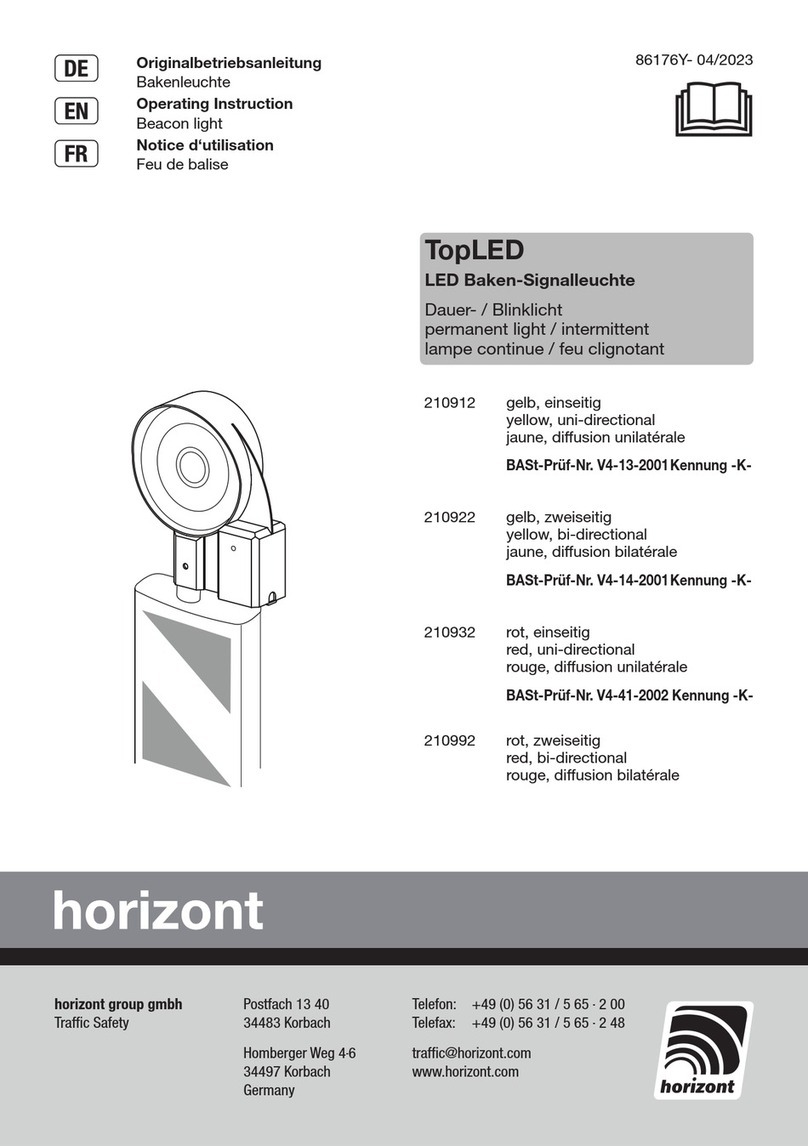
Horizont TopLED 210912 User manual

Horizont
Horizont FlashMax Synchro User manual

Horizont
Horizont Euro-Blitz 208801LED User manual

Horizont
Horizont FlashMax Synchro User manual

Horizont
Horizont optima LED 20886LED User manual

Horizont
Horizont Euro-Synchron Euro-Blitz 208821LED User manual

Horizont
Horizont Euro-Blitz User manual