manuals.online logo
Brands
  1. Home
  2. •
  3. Brands
  4. •
  5. Horn Tools
  6. •
  7. Automobile Accessories
  8. •
  9. Horn Tools HMBXRRB020 Series User manual

Horn Tools HMBXRRB020 Series User manual

www.horntools.com
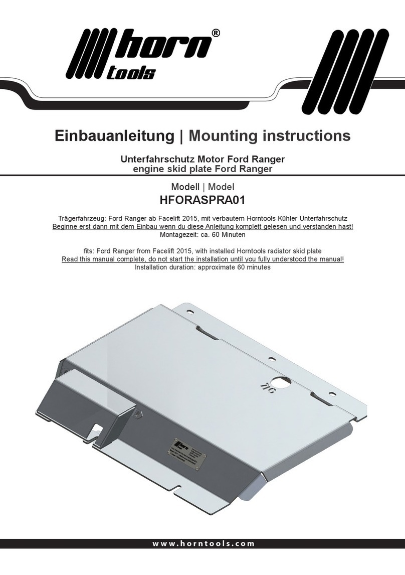
Einbauanleitung | Mounting instructions
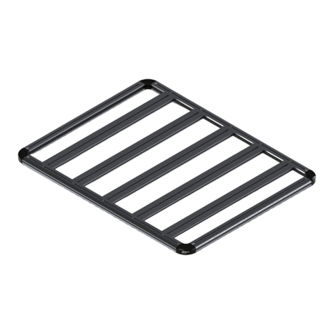
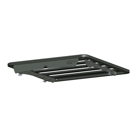
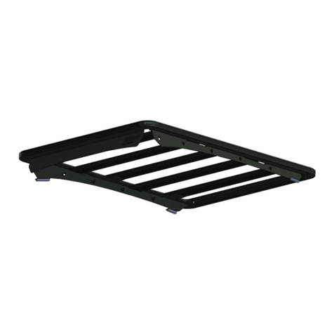
Mercedes Benz X Klasse Dachträger | Roof Rack
Modell | Model
HMBXRRB020_X
Trägerfahrzeug: Mercedes Benz X Klasse BJ: 2017 –
fits: Mercedes Benz X Class manufacturing year 2017 and following
Dieses Produkt kann nur auf Fahrzeuge mit originaler Dachreling montiert werden
this product only fit’s cars with OEM roof railing
2
Stückliste
Anzahl
quantity
Bild
image
Zeichnungsnummer
drawing number
Beschreibung
description
1
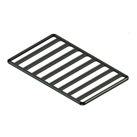
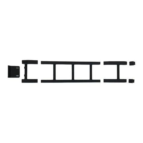
HMBXRRB020_X_02 Heck Segment
rear segment
1
HMBXRRB020_X_03 Mitten Segment
mid segment
1
HMBXRRB020_X_04 Front Segment
front segment
1
HMBXRRB020_X_05 Montageblech Fahrerseite
mounting bracket driverside
1
HMBXRRB020_X_06 Montageblech Beifahrerseite
mounting bracket codriverside
8
HMBXRRB020_X_07 Segment Verbinder
segment connector
1
HKLEBER21G Silikon Dichtmasse
silicone sealant
3
Dachträger Mercedes Benz X-Klasse | Roof Rack
Artikel
article
Größe
size
Festigkeit
strength
Kop󰀨orm
head
Oberäche
surface DIN / ISO Stk.
quant.
Schraube
bolt M8x20 8.8 Linsenkopf
lens head ISO7830-1 16
Scheibe rund
washer round M8 Kunststo󰀨scheibe
Plastic washer 16
Schnorr Scheibe
Schnorr washer M8 32
Hutmutter
hat nut M8 Hut
hat DIN1587 16
Schraube
bolt M8x20 8.8 Hex DIN933 16
Schraube
bolt M8x30 8.8 Linsenkopf
lens head ISO7830-1 8
Mutter
nut M8 Selbstsichernd
self locking DIN985 8
Scheibe
washer M8 Verzinkt
galvanized DIN125 24
Scheibe
washer M8 Wasserdicht
Water thight
Verzinkt
galvanized 8
Dichtung
sealing
Gummidichtung
Rubber sealing 4
Schraubenliste | boltlist
4
Demontage Sonnenblende / Innenbeleuchtung / Einstiegsgri󰀨e /
A-Säulenabdeckung | Removal of the sun visor / a pillar cover / ambient light
Um die originale Dachreling zu demontieren muss der Dachhimmel im Inneren des Fahrzeuges gelöst werden.
To demount the OEM roof railing you have to remove the roof liner.
Abb 1)
123
Abb 1) 1: Innenbeleuchtung/Sonnenbrillenhalter herunter ziehen, dieser ist mit Clips befestigt.
Ambient lights / glasses carrier is removed, it’s held by clips.
Abb 1) 2: Fahrer & Beifahrer Sonnenblende demontieren, Schrauben sind mit „aufgeklipptem“
Kunststo󰀨deckel abgedeckt, dieser lässt sich mit Hilfe eines Schraubendrehers entfernen.
Ebenfalls auf der Fahrerseite wiederholen.
Demount sun visor, the bolts are covered with a plastic cap, it can be removed with a screw
driver. Repeat this on the driverside too.
Abb 1) 3: Einstiegsgri󰀨e abschrauben, auch hier sind die Schrauben mit Kunststo󰀨deckeln abgedeckt, im
Anschluss A – Säulenabdeckung herausziehen, diese ist mit Clips befestigt. Das selbe auf der
Fahrerseite.
Disassemble the entry handle, it’s bolts are also covered by plastic cap then remove the A-pillar
cover, it is held by clips and can be pulled out. Do the same on the driver side.
1.
5
Zeigt das Fahrzeug mit den oben beschriebenen Teilen demontiert.
The picture shows the car with the described removing steps already done.
Demontage der Haltegri󰀨e / Innenverkleidungen | Removing of the inner grab
rails / inner covers
2.
An jeder Türe ist das Fahrzeug mit einem herabklappbaren Haltegri󰀨 ausgestattet. Dieser hält ebenfalls den
Dachhimmel in Position.
The car is equipped with 4 inner foldable handles. They also hold the roof liner in place and need to be removed.
Abb 2)
1 2
Abb 2) 1: Mit einem kleinen Schraubendreher den gezeigten Clip nach Innen drücken dann den oberen
Teil ( Abb 2) 2) nach oben ausfahren.
By the use of a small screw driver bend the shown clip (Abb 2) 1) towards the inside of the car,
now move Abb 2) 2 up.
Abb 1)
6
Den zuvor erklärten Schritt auf jeden Haltegri󰀨 im Innenraum anwenden. Wenn der Gri󰀨 abgenommen wurde
stehen Blechhalter nach Innen. Diese können vorsichtig mit einer Spitzzange zusammengedrückt werden und
ebenfalls ausgefahren werden. Beim Wiedereinbau ist darauf zu achten die Blechhalter wieder in die originale
Form zu drücken um sie wieder ordnungsgemäß im Karosserieblech durch einklicken zu befestigen.
Repeat the previously described routine on every inner foldable handle. After you demounted the handle, steel
sheet metal clips show inside the mounting holes of the handle. To remove them gently squeeze them together
with a calliper and pull them out. When you are reassembling the car take special care to bend the sheet metal
clips into their original form. The original shape ensures that they are xated properly in the cars chassis.
Abb 3)
123
Auf Fahrer und Beifahrerseite sind die
B-Säulen mit Kunststo󰀨abdeckungen
verkleidet. Um diese zu entfernen lösen Sie
die hinteren Einstiegs - Haltegri󰀨e (Abb 3) 1).
Ziehen Sie die Abdeckung der Gurt
Höhenverstellung ab (Abb 3) 2). Dann
haben Sie Zugang zur Schraube die
den Gurt oben hält (Abb3) 2) mit dieser
gelöst können Sie den Gurt von der
Seitenverkleidung abnehmen. Jetzt die mit
einem Kunststo󰀨deckel per Clip verdeckte
Schraube in Abb 3) 2 herausdrehen. Als
nächstes die Abdeckung von der Seitenwand
ablösen. Führen Sie dieselben Schritte auch
auf der Beifahrer Seite aus.
On both, driver and codriver side the
B-pillars are covered with a plastic cap
(visible in Abb 3). To demount this you have
to unbolt the rear entry handles held by the
bolts shown in Abb 3) 1. Now you can pull o󰀨
the plastic cap (use a small screwdriver to
lift the plastic wings of the cap) which covers
the upper belt joint, with the cap o󰀨 you can
unbolt the upper belt joint (Abb 3) 2). Now
nally with a screwdriver pop o󰀨 the plastic
cap which covers the upper bolt which holds
the plastic side cover in place (Abb 3) 3).
disassemble the bolt in Abb 3) 3. With that
done you can pull o󰀨 the side plastic cover,
it is now only held by a few plastic clips, pull
gentle not to damage them. Do the same on
codriver side.
Abb 3) Zeigt die Seitenverkleidung mit den oben genannten Montageschritten bereits ausgeführt!
Shows the side cover disassembled, the described steps are already done!
7
Abb 4)
1
Neben den hinteren Sitzen sind die C –
Säulen mit einer Kunststo󰀨verkleidung
abgedeckt. Diese ist lediglich mit
Kunststo󰀨clips befestigt und kann durch
vorsichtiges Ziehen demontiert werden.
Besides the rear seats the C-pillars are
covered with plastic cover, this is only held
by a few plastic clips. To demount the cover
gently pull it away from the C-pillar.
Abb 5)
1 2
Über der hinteren Sitzreihe sind zwei Kunststo󰀨clips angebracht, diese können durch vorsichtiges Ziehen
entfernt werden Abb 5) 1.
Above the rear seats there are two plastic clips, they can be removed by gently pulling them o󰀨 the roof Abb 5) 1.
8
Demontage der originalen Dachträger | demounting of the OEM roof railings
Nun kann der Dachhimmel einige Zentimeter vorsichtig nach unten gezogen werden. Jetzt sind die
Verschraubungen der originalen Dachreling ersichtlich Abb 6 – vorne, Abb 7 – hinten.
Now you can gently pull the roof liner down 2 to 3 inches. With that done you can see the xtures of the OEM
roof rails. Abb 6 shows the front xtures, Abb 7 shows the rear ones.
3.
Abb 6) Abb 7)
Lösen sie die Schrauben der originalen Dachreling und nehmen Sie diese vom Dach ab.
Unbolt these nuts and thake o󰀨 the OEM roof railing.
9
Zusammenbau des Dachträgers | Assembly of the roof rack4.
Abb 8)
10
Abb 9)
1 2
Mit den 8 HMBXRRB020_X_07 werden die drei Einzelsegmente zusammengeschraubt Abb 9) 2.
Verwenden Sie hier die gezeigten Kunststo󰀨scheiben und die M8x20 Linsenkopfschrauben. Sollte bei den
Stößen der Einzelsegmente ein Spalt größer 1mm entstehen diesen mit einem der mitgelieferten Gummiringen
abdecken. Es empehlt sich die Schrauben erst anzuziehen wenn die Spalte auf allen Stößen mit Drücken so
weit wie möglich minimiert wurden.
Wie in Abb 9) 1 gezeigt, wird der Dachträger auf die Karosserie Montagebleche verschraubt. Dies passiert an
allen 4 Flanschen mit den beiliegenden M8x20 Schrauben, oben ohne Beilagscheibe unten mit einer normalen
M8 Scheibe und den Hutmuttern. Diese Schrauben noch nicht komplett festziehen.
With the 8 HMBXRRB020_X_07 you connect the 3 big segments. Use the M8x20 lens head bolts with the round
plastic washers to bolt them together. Caused by the welding fabrication of the roof rack it can be possible that
the assembled roof rack is showing gaps bigger than 1mm at the joints. To cover this visible gap we provided you
with rubber rings, if there is a gap bigger than 1mm please add a rubber ring to cover the gap.
The roof rack is then xed to the cabin mounting brackets using the M8x20 hex bolts, no washer on roof rack side
and a M8 washer on the bottom side plus the hat nut. Do not tighten these bolts yet, it is benecial when you can
move the cabin mounts while positioning them on the cars roof.
11
Positionieren/Befestigen des Dachträgers auf dem Fahrzeug | Positioning /
mounting of the roof rack on the car
Platzieren Sie die Gummidichtungen auf den Verschraubungspunkten am Fahrzeug. Prüfen Sie ob die
Ausschnitte für die Schrauben in das Halteblech unter der Dachhaut passen. Ebenso Dachträger auf die
Gummidichtungen aufsetzen und Schrauben von Oben durchstecken um zu prüfen ob deren Ausrichtung passt.
Danach Dachträger nochmals abnehmen. Dichtmasse auf beiden Seiten der Gummidichtung aufbringen, ca. 1
Zentimeter von der Außenkante der Dichtung parallel zur Außenäche, wie in Abb. 10) 1 gezeigt.
5.
Abb 10)
1
Danach Gummidichtungen auf Dach passend auf den Bohrungen aufbringen und anschließend
zusammengebauten Dachträger auf die Dichtungen positionieren. Mit den M8x30mm Schrauben + oben
der dichtenden Beilagscheiben und unterm Dach auf dem Halteblech mit den M8 Beilagscheiben +
der M8 Sicherungsmutter befestigen. Nun können auch die Schrauben von Abb 9) 1 entsprechend der
Drehmomenttabelle auf der letzten Seite angezogen werden.
Alle Bolzen der Baugruppe mit dem unten angegebenen Drehmoment festziehen.
Place the rubber selants with the roof rack above on top of the car, check if the drills and the cutouts in the
sealant align properly. When they do, add the silicone sealant (in the tube) to the rubber sealants as shown in
Abb 10) 1 to both sides of the rubber sealant. Now place the roof rack with the rubber sealant below on the car.
Fixate the assembly with the M8x30 bolts plus the M8 watertight washer on top and the M8 washer + M8 secure
nut on the inside to the car. Torque to the momentum described on the last page. Now you can also tighten the
bolts from Abb 9) 1.
Tighten all bolts with the torque value dened on the last page of this installation manual.
12
Zusammenbau des Innenraumes | Assembly of the cars interior after mounting
of roof rack assembly
Wenn die Dichtmasse getrocknet ist prüfen Sie die Wasserdichtheit des Aufbaus. Gegebenenfalls dass Wasser
in den Innenraum eintritt entsprechenden Karosseriehalter lösen und mehr Dichtmasse einfügen.
After the black silicone sealant has dried check if the construction is water tight. If there is water coming through
to the inside of the car unbolt the cabin mount that is in question. Add more silicone sealant to it and reassemble
it, then check water tightness again.
6.
Nun den Innenraum wieder zusammenbauen, folgen Sie dazu den Schritten 1 bis 2 in umgekehrter Reihenfolge.
Alle Schrauben bei jeder Inspektion nachziehen in regelmäßigen Abständen die Wasserdichtheit des Aufbaus
prüfen.
Now you can reassemble the interior, following the steps 1 to 2 in reverse direction. On each inspection fasten all
bolts again, or check if they are fastened. In periodical inspections check the water tightness of the construction
to avoid damage in case of excessive rain.
13
Vorspannkräfte und Anziemomente für Schaftschrauben aus Stahl
Regelgewinde
Abmessung Vorspannkraft (kN) Anziehmoment (Nm)
Festigkeits-
klasse 4.6 5.6 8.8 10.9 12.9 4.6 5.6 8.8 10.9 12.9
M 4x0,70 1,29 1,71 3,9 5,7 6,7 1,02 1,37 3,0 4,4 5,1
M 5x0,80 2,1 2,79 6,4 9,3 10,9 2,0 2,7 5,9 8,7 10
M 6x1,00 2,96 3,94 9,0 13,2 15,4 3,5 4,6 10,0 15,0 18,0
M 8x1,25 5,42 7,23 16,5 24,2 28,5 8,4 11,0 25,0 36,0 43,0
M 10x1,50 8,64 11,5 26,0 38,5 45,0 17,0 22,0 49,0 72,0 84,0
M 12x1,75 12,6 16,8 38,5 56,0 66,0 29,0 39,0 85,0 125,0 145,0
M 14x2,00 17,3 23,1 53,0 77,0 90,0 46,0 62,0 135,0 200,0 235,0
M 16x2,00 23,8 31,7 72,0 106,0 124,0 71,0 95,0 210,0 310,0 365,0
M 18x2,50 28,9 38,6 91,0 129,0 151,0 97,0 130,0 300,0 430,0 500,0
M 20x2,50 37,2 49,6 117,0 166,0 194,0 138,0 184,0 425,0 610,0 710,0
M 22x2,50 46,5 62,0 146,0 208,0 243,0 186,0 250,0 580,0 830,0 970,0
M 24x3,00 53,6 71,4 168,0 239,0 280,0 235,0 315,0 730,0 1050,0 1220,0
M 27x3,00 70,6 94,1 221,0 315,0 370,0 350,0 470,0 1100,0 1550,0 1800,0
M 30x3,50 85,7 114,5 270,0 385,0 450,0 475,0 635,0 1450,0 2100,0 2450,0
M 33x3,50 107,0 142,5 335,0 480,0 560,0 645,0 865,0 2000,0 2800,0 3400,0
M 36x4,00 125,5 167,5 395,0 560,0 680,0 1080,0 1440,0 2600,0 3700,0 4300,0
M 39x4,00 151,0 201,0 475,0 670,0 790,0 1330,0 1780,0 3400,0 4800,0 5600,0
Anzugsdrehmomente, alle Schrauben mit dem angegebenen Drehmoment anziehen.
Torque down all bolts in accordance to below guidelines
www.horntools.com
horntools GmbH
Wallenmahd 23 . 6850 Dornbirn . AUSTRIA
email: o󰀩[email protected]
UID: ATU65090439

This manual suits for next models

6

Other Horn Tools Automobile Accessories manuals
Horn Tools HISDMSPTC01 User manual

Horn Tools

Horn Tools HISDMSPTC01 User manual

Horn Tools HMIL2RSA01 User manual

Horn Tools

Horn Tools HMIL2RSA01 User manual

Horn Tools HBRRF1613 User manual

Horn Tools

Horn Tools HBRRF1613 User manual

Horn Tools HMBXMSPM02 User manual

Horn Tools

Horn Tools HMBXMSPM02 User manual

Horn Tools ExRoof HBRRF2415 User manual

Horn Tools

Horn Tools ExRoof HBRRF2415 User manual

Horn Tools HUFJIMGJLAD01 User manual

Horn Tools

Horn Tools HUFJIMGJLAD01 User manual

Horn Tools ExRoof HBRRF1714 User manual

Horn Tools

Horn Tools ExRoof HBRRF1714 User manual

Horn Tools ExRoof HBRRF3015 User manual

Horn Tools

Horn Tools ExRoof HBRRF3015 User manual

Horn Tools HCDST01 User manual

Horn Tools

Horn Tools HCDST01 User manual

Horn Tools HSW9900ISDMDY PA User manual

Horn Tools

Horn Tools HSW9900ISDMDY PA User manual

Horn Tools HVWRR02FIT User manual

Horn Tools

Horn Tools HVWRR02FIT User manual

Horn Tools HISDMSPAB01 User manual

Horn Tools

Horn Tools HISDMSPAB01 User manual

Horn Tools HISDMSPRA01 User manual

Horn Tools

Horn Tools HISDMSPRA01 User manual

Horn Tools HMIL2RR02FIT User manual

Horn Tools

Horn Tools HMIL2RR02FIT User manual

Horn Tools HTOHIRSA01 User manual

Horn Tools

Horn Tools HTOHIRSA01 User manual

Horn Tools HJIMRR02FIT User manual

Horn Tools

Horn Tools HJIMRR02FIT User manual
Horn Tools HPSAL2RR02FIT User manual

Horn Tools

Horn Tools HPSAL2RR02FIT User manual

Horn Tools HFORASPAB01 User manual

Horn Tools

Horn Tools HFORASPAB01 User manual

Horn Tools HISDMSPTA01 User manual

Horn Tools

Horn Tools HISDMSPTA01 User manual

Horn Tools HBREZLDR User manual

Horn Tools

Horn Tools HBREZLDR User manual

Horn Tools HJIMGJRR20 User manual

Horn Tools

Horn Tools HJIMGJRR20 User manual

Horn Tools AHBRTS User manual

Horn Tools

Horn Tools AHBRTS User manual

Horn Tools HSW9900LUXPLATE16 User manual
Horn Tools

Horn Tools HSW9900LUXPLATE16 User manual

Horn Tools AHBRTRMO01 User manual

Horn Tools

Horn Tools AHBRTRMO01 User manual

Popular Automobile Accessories manuals by other brands

Precision 371929 installation instructions

Precision

Precision 371929 installation instructions

Gewiss JOINON WALLBOX I-CON DLM User and installation manual

Gewiss

Gewiss JOINON WALLBOX I-CON DLM User and installation manual

Dakota Digital HDX-54C-PU Instrument Installation

Dakota Digital

Dakota Digital HDX-54C-PU Instrument Installation

Rhino-Rack Rhino 2500 Series installation instructions

Rhino-Rack

Rhino-Rack Rhino 2500 Series installation instructions

SportRack SR2901BLR installation guide

SportRack

SportRack SR2901BLR installation guide

Top Auto BRK600 user manual

Top Auto

Top Auto BRK600 user manual

RACLET SAFARI Erection guidelines

RACLET

RACLET SAFARI Erection guidelines

Cruz Evo Rack Alu A32-170 Assembly instructions

Cruz

Cruz Evo Rack Alu A32-170 Assembly instructions

Michelin 12266 user guide

Michelin

Michelin 12266 user guide

Rac Black Box Installation

Rac

Rac Black Box Installation

Thule 2063 parts list

Thule

Thule 2063 parts list

Thule 280 manual

Thule

Thule 280 manual

POOL-LINE BO0018 Assembly instructions

POOL-LINE

POOL-LINE BO0018 Assembly instructions

Laser 4832 manual

Laser

Laser 4832 manual

Connects2 CTSPO008.2 installation guide

Connects2

Connects2 CTSPO008.2 installation guide

Buyers Products Company 1501100 installation instructions

Buyers Products Company

Buyers Products Company 1501100 installation instructions

Prestigio RoadScout 3110 user manual

Prestigio

Prestigio RoadScout 3110 user manual

Trane Technologies Thermo King TriPac Evolution Operator's manual

Trane Technologies

Trane Technologies Thermo King TriPac Evolution Operator's manual

manuals.online logo
manuals.online logoBrands
  • About & Mission
  • Contact us
  • Privacy Policy
  • Terms and Conditions

Copyright 2025 Manuals.Online. All Rights Reserved.