+1 (813) 783-8058
Fax: +1 (813) 783-2407
Wiring Instructions
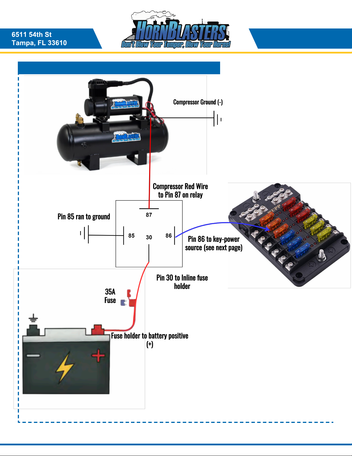
Pin 30: This pin will connect to the battery positive terminal. You MUST use the supplied 10-gauge wire for this connection. Use
the supplied bright-green terminal to connect the red wire to this pin. Cut our fuse holder in half to make two ends, and place this
in between pin 30 and the battery positive terminal.
Pin 86: This pin will connect to a key-power source. This can be tricky if you've never installed our kits before. You are looking to
connect this pin to any circuit that is ONLY ON WHEN THE VEHICLE IS ON. This will prevent your kit from running when the
vehicle is off. Common key-power sources include the cigarette lighter fuse, sunroof, radio, trailer running lights, daytime running
lights, etc.
Pin 85: Route a lead from this pin to the frame of the vehicle as a ground point. You may use the supplied Blue or Grey wire for
this connection.
Pin 87: Take the red lead coming off the compressor/tank combo and connect it directly to this pin.
Your relay is now wired and ready for use. You can use a small lead of wire to connect pins 30 & 86 together to test the relay. If
you have this wired correctly, the relay should make a light 'click' sound when the two pins are connected. This means the relay
is turning on and off properly. When you start the vehicle, it will send power to pin 86 and turn the relay on, which will allow the
compressor to run.
Key-Power-Source (Using a toggle switch)
Finding a good key-power source for your kit is one of the most challenging aspects of the install process. If you've never
worked on a vehicle before this may seem impossible. If you are not comfortable with tapping into the vehicle's existing circuits,
you can use a toggle switch to ensure the compressor doesn't run when the vehicle is off, without having to tap into any existing
electrical components on the vehicle. To do this, locate the supplied toggle switch that came with your horn kit. Wire one lead of
the toggle switch to the output side of your inline fuse holder, and take the opposite lead of the toggle switch to pin 86 on the
relay. When you flip the switch on, the relay will switch on and allow the compressor run. Wiring your kit this way unfortunately
means that you MUST turn the switch off with the vehicle, otherwise the compressor could run overnight and drain your battery.
Key-Power-Source (Normal Method)
Locating a key-power source can be a bit tricky on some vehicles. If you're having trouble locating a fuse that is only hot when
the vehicle is on, you can go online to https://fuse-box.info/. Select your vehicle make/model and you will be shown a
breakdown of the fuses on your vehicle. This works great for finding good candidates, such as the radio fuse, sunroof, running
lights, or even the cigarette lighter/USB power outlet fuses. You can use a test light to check whether or not the fuses are hot
with the key in the off position. Route the black probe/clip to the battery negative terminal (-) and use the red probe on the metal
contacts of the fuse(s) you want to check. If the light comes on, your fuse is hot. If the light does not turn on, start the vehicle and
check for current. The light should illuminate now that the vehicle is running.
Wiring the Relay
6511 54th St
Tampa, FL 33610
Horn Activation
The horn itself can be wired up a few different ways. If you would like to honk your train horns with the steering wheel, start by
locating the factory horn. On most vehicles, the factory horn is directly ahead of the radiator, or mounted in a fender-well. Once
the OEM horn is located, we need to find the positive wire connected to the stock horn. Using the supplied scotchlok/tap
connector, splice a new lead to the positive horn wire and route it over to a toggle switch (optional). Route the opposite lead of
the toggle switch out to the air horn. You can connect this lead to one of the two wires on the solenoid valve for the horn. Take
the opposite wire from the horn and route it to the frame as a ground point. At this point, press the steering wheel and listen for
a click from the air horn solenoid valve. If you have air in the tank already, the horn should honk.
A push button can be used to honk the horns instead of the steering wheel if you prefer. Route one lead from a push button to the
battery positive terminal, and route the opposite lead of the button to the horn solenoid. Ground the opposite lead to the frame.
12