manuals.online logo
Brands
  1. Home
  2. •
  3. Brands
  4. •
  5. Geovent
  6. •
  7. Industrial Equipment
  8. •
  9. Geovent ENERGY ARM User manual

Geovent ENERGY ARM User manual

ENERGY ARM
Power, Compressed air and High Vacuum Extraction
Version 2.1 02/09 -2014
INSTRUCTION MANUAL
www.geovent.com.pl
2
1.0 General safety precautions
IMPORTANT – Carefully read the entire instruction
manual before mounting and commissioning.
Please keep these instructions in a safe place and
instruct all users in the function and operation of the
energy arm.
Installation and service should only be carried out after
studying section 4 thoroughly.
Avoid detatching any factory-mounted parts, since it
impedes the commissioning of the equipment.
All electrical installations must be carried out by an
authorised electrician.
1.1 Danger
It is potentially deadly to touch the wires under the
Yellow cover shield.
Use extreme caution.
1.2 Area of application
The GEOVENT Energy arm is used where power, point
extraction and compressed air is needed at a
workstation.
The energy arm is NOT for use is areas categorized as
ATEX zones. Use only ATEX approved material.
1.3 Handling
Use protective gloves when transporting and installing
the energy arm.
1.4 Technical data
Power outlet: 1x230V, 13A
Supply: 3x400V, 16A
Compressed air: 2 outlets,
Extraction: High Vacuum with ø50 ap valve.
1.5 Construction
Wall console + arm: Painted steel, 50x100 prole, The
swivel joint of the console pivots up to 270°.
Protective box: Powdercoated, galvanized steel.
Suspension: Balancer and hose (GeoFlex P2A 1000)
for hose- and cables.
Hose for High Vacuum and cables are kept in the spiro-
duct on the arm.
2.0 Installation
The energy arm is supplied un-assembled. Depending
on the model it consists of one arm and spiro duct, one
protective box with outlets, one assembly kit with balan-
cer, bend with suspension and hose with hose clamps
and rubber bands for ducting.
Any ordered alterations will be stated on the order
conrmation/invoice.
Before mounting, please consider:
• Ample space for satisfactory use of the arm.
• Optimum height of installtion.
• Ducting and connections.
• First fasten the wall console of the arm on a
sturdy wall - e.g. a concrete wall.
• Mount arm on console.
• Fit spiro duct on the arm.
• Pass cables and hoses through spiroduct,
exible hose and bend.(Remember to attach
hose clamp and rubber band prior to this.)
• Connect cables and hoses to the satellite.
• Suspend the satellite.
Balancer
Satellite box
with outlets
Bend with
suspension
Support arm
Spiro duct
Table of content
1.0 General safety precautions . . . . . . . . . . . . . . . . . . 2
1.1 Danger ..................................2
1.2 Area of application .........................2
1.3 Handling ................................2
1.4 Technical data.............................2
1.5 Construction .............................2
2.0 Installation ...............................2
2.1 Power connection .........................3
3.0 User instruction............................3
4.0 Maintenance .............................3
5.0 Liability . . . . . . . . . . . . . . . . . . . . . . . . . . . . . . . . . . 4
6.0 Declaration of conformity ....................4
3
Suspension available after request. Shown here is a
balancer, which will automatically pull the satellite back
to its position after use.
Alternatively the suspension can be at a xed height
keeping the satellite in place at a predened height.
In this case a wire is attached to the arm and the
satellite maintaining the desired height.
When mounting using bend and suspension a wire is
placed in the hose to maintain a xed distance between
bend and satellite. Adjust distance as you wish.
Energy arm with satellite.
Shown with intermediate joint and suspension with
balancer.
2.1 Connect to power
Power connection must be carried out by a trained and
certied electrician.
Recommended transformer effect: 70 W
Connection of elctrical board: Please refer to the docu-
mentation for the specifc board.
The satellite as seen from above
with the eyelet for the wire.
Extraction
On/off
ø50 mm Flap
valve for High
Vacuum
Tool holder
Compressed air
1x230V, 13A
3x400V, 16A
3.0 User instruction
Pull the satellite down to the desired working height.
After use disconnect the used connections and pull the
satellite down and let it roll back up.
Do not release the satellite before it is in place.
The tool holder i intended for light hand tools only.
4.0 Maintenance
The energy arm does not require further maintenance.
However, the supply connections should be inspected
regularly for leaks/breakage.
4
5.0 Liability
Warranty
Geovent A/S grants a warranty for products, which are
defective, when it can be proved that the defects are
due to poor manufacture or materials on the part of
Geovent. The warranty comprises remedial action
(reparation or exchange) until one year after date of
shipment.
No claims can be made against Geovent A/S in relation
to loss of earnings or consequential loss as a result of
defects on products from Geovent.
Wear on parts such as lter cartridges is not included in
the warranty.
User liability
In order for Geovent to be capable of granting the
declared warranty, the user/tter must follow this
Instruction Manual in all respects.
Under no circumstances may the products be changed
in any way, without prior written agreement with
Geovent
We refer to sales- and delivery terms at
www.geovent.com
HOVEDGADEN 86 • DK-8831 LØGSTRUP
www.geovent.com.pl
Dystrybucja w Polsce
tel.+48 799923945
E-mail:[email protected]
6.0 Declaration of conformity
Geovent A/S
hereby declares that:
The product: Energy arm
has been manufactured in compliance with the
following directives and standards:
European Parliament and Council Directive 2006/42/
EC of 17 May 2006 on machinery, and amendments to
Directive 95/16/EC.
EN ISO 14121-1:2007 Risk assessment – part 1
EN ISO 12100-1:2005 Basic concepts and general
principles for design.
EN ISO 12100-1:2009 construction and design
Part 1: Basic terminology and
methodology
EN ISO 12100-2:2005 Basic concepts and general
principles for design.
EN ISO 12100-2:2009 Construction and design
Part 2: Technical principles
Authorized to maintain technical le:
Ole Madsen
Date: 02/09 - 2014
Position: Managing director
Name: Thomas Molsen
Signature : ____________________________

Other Geovent Industrial Equipment manuals

Geovent COMPACT arm User manual

Geovent

Geovent COMPACT arm User manual

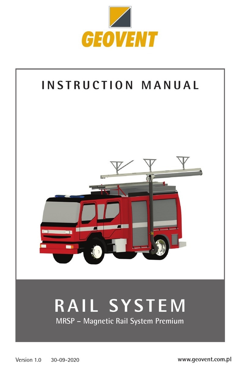
Geovent Magnetic Rail System Premium User manual

Geovent

Geovent Magnetic Rail System Premium User manual

Geovent GeoFilter GFB2 Tower 6-2 User manual

Geovent

Geovent GeoFilter GFB2 Tower 6-2 User manual

Geovent PRS User manual

Geovent

Geovent PRS User manual

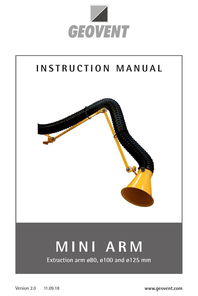
Geovent MINI ARM User manual

Geovent

Geovent MINI ARM User manual

Geovent 25 User manual

Geovent

Geovent 25 User manual

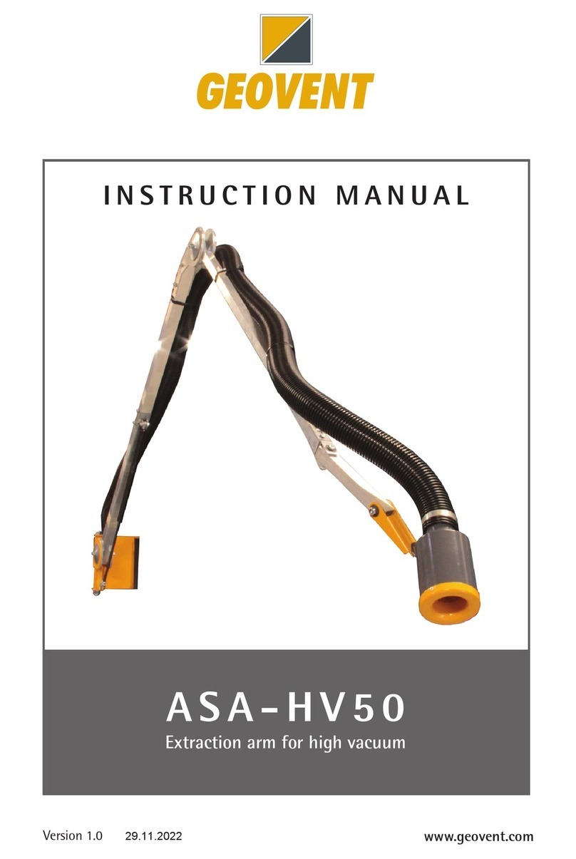
Geovent ASA-HV50 User manual

Geovent

Geovent ASA-HV50 User manual

Geovent GEOFILTER DUST User manual

Geovent

Geovent GEOFILTER DUST User manual

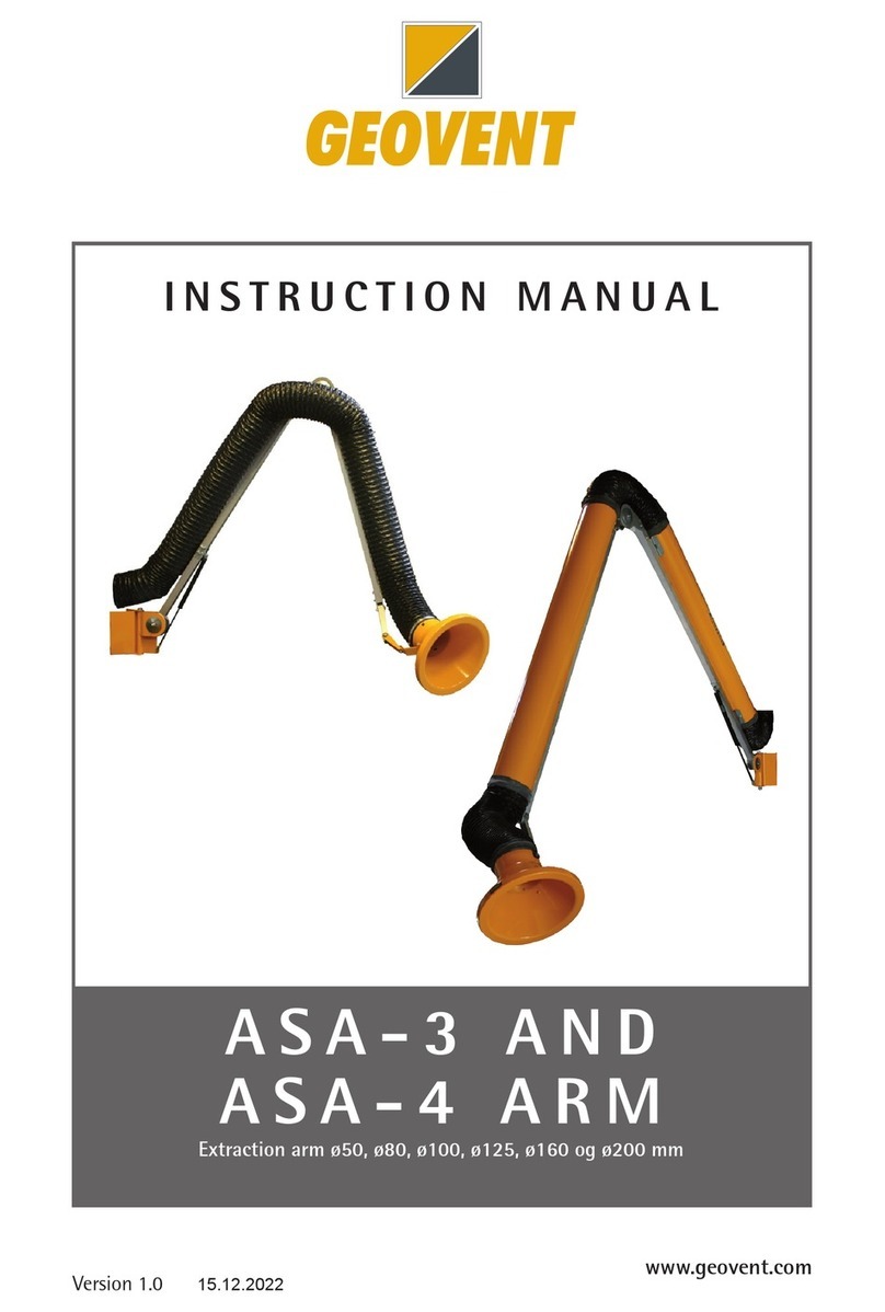
Geovent ASA-3 Series User manual

Geovent

Geovent ASA-3 Series User manual

Popular Industrial Equipment manuals by other brands

Formax FD 280 Operator's manual

Formax

Formax FD 280 Operator's manual

ITW Simco Ion IQ Power Nozzle Installation and operating instructions

ITW

ITW Simco Ion IQ Power Nozzle Installation and operating instructions

Loveshaw LD16AP owner's manual

Loveshaw

Loveshaw LD16AP owner's manual

SCHUNK SGB 32 Assembly and operating manual

SCHUNK

SCHUNK SGB 32 Assembly and operating manual

ABB A140-M55 Operation manual

ABB

ABB A140-M55 Operation manual

Weber mt IVURplus 40 Operating and maintenance manual

Weber mt

Weber mt IVURplus 40 Operating and maintenance manual

Fastbind C400 user manual

Fastbind

Fastbind C400 user manual

ATOMSTACK X40 Pro user manual

ATOMSTACK

ATOMSTACK X40 Pro user manual

Mapal Hydro Mill Chuck Installation and operating instructions

Mapal

Mapal Hydro Mill Chuck Installation and operating instructions

Wilo Wilo-Flumen OPTI-TR 20-1 Installation and operating instructions

Wilo

Wilo Wilo-Flumen OPTI-TR 20-1 Installation and operating instructions

VIBCO DC manual

VIBCO

VIBCO DC manual

Maxon EC frameless DT installation manual

Maxon

Maxon EC frameless DT installation manual

Graziadio & C. K Series Assembly instructions

Graziadio & C.

Graziadio & C. K Series Assembly instructions

Code Blue CB 9 Series Administrator's guide

Code Blue

Code Blue CB 9 Series Administrator's guide

Conel CLEAR FILL operating instructions

Conel

Conel CLEAR FILL operating instructions

HOLLISTER-WHITNEY GLV-40D1 Series instruction manual

HOLLISTER-WHITNEY

HOLLISTER-WHITNEY GLV-40D1 Series instruction manual

CLAS OH 0850 manual

CLAS

CLAS OH 0850 manual

SIP 01944 product manual

SIP

SIP 01944 product manual

manuals.online logo
manuals.online logoBrands
  • About & Mission
  • Contact us
  • Privacy Policy
  • Terms and Conditions

Copyright 2025 Manuals.Online. All Rights Reserved.