LMAN0073-01-EN
Hazardous Location Series
02/2021 Page 1
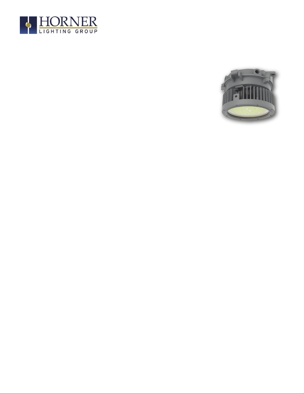
ETG-HHR
HazLoc High Bay Round User Manual
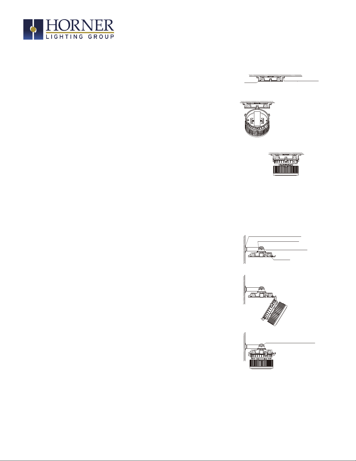
GENERAL SAFETY INFORMATION
electric shock, falling parts, cuts/abrasions and other hazards, please read
• DO NOT INSTALL DAMAGED PRODUCT!
WARNING:
RISK OF ELECTRICAL SHOCK
CAUTION:
RISK OF INJURY
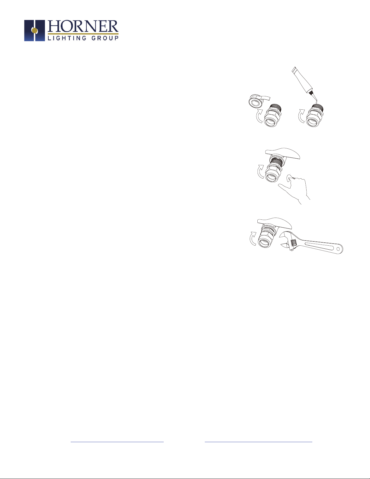
• Tightly close when energized for safety
RISK OF FIRE