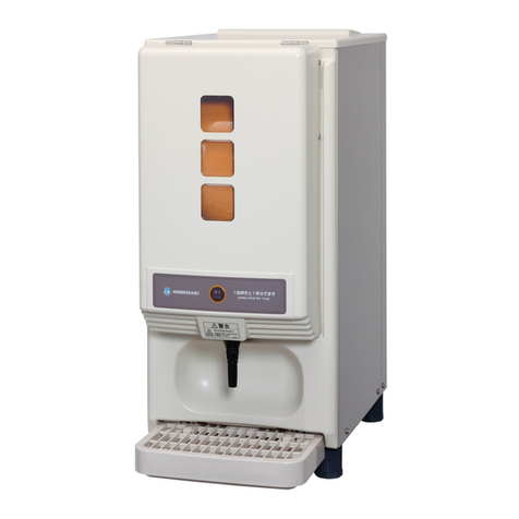
Hoshizaki DBF-40SAC User manual

SERVICE MANUAL
HOSHIZAKI
DRAFT BEER DISPENSER
DBF-40SAC
NO. B074-931
ISSUED: FEB. 7, 2014
REVISED:
MODEL
(Australia)

CONTENTS
GENERAL INFORMATION
1. SAFETY INSTRUCTIONS ---------------------------------------------------------------------------- 1, 2
2. CONSTRUCTION
BEER CIRCUIT-------------------------------------------------------------------------------------------------------------- 3
3. DIMENSIONS/SPECIFICATIONS --------------------------------------------------------------------------------- 4
TECHNICAL INFORMATION
4. CONTROL
(1) GENERAL OPERATION ------------------------------------------------------------------------------------------5 - 6
(2) INPUT/OUTPUT -----------------------------------------------------------------------------------------------------7, 8
(3) WIRING DIAGRAM ---------------------------------------------------------------------------------------------------- 9
5. REFRIGERATION CIRCUIT --------------------------------------------------------------------------------------- 10
SERVICE INFORMATION
6. SERVICE DIAGNOSIS -----------------------------------------------------------------------------11 - 20
(1) Beer is not cold
(2) No beer is dispensed
(3) Beer will not stop
(4) Beer tap keeps dripping beer
(5) Underfoaming
(6) Overfoaming
(7) large bubbles
(8) Beer tastes strange (watery)
(9) Cylinder runs out of gas easily
(10) Cooling water mixed with beer comes out of overflow pipe on unit front
(11) Beer tap joint leaks beer
(12) Unit leaks water
(13) Abnormal noise
(14) Burning smell
(15) After unit is turned on, refrigeration circuit clicks every 3 - 5 minutes
Condenser fan motor is running, but beer is not cold
(16) Main power supply earth leakage circuit breaker trips
(17) Instructions for handling controller board
7. PARTS DESCRIPTION AND REPLACEMENT ----------------------------------------------21 - 32
8. DISASSEMBLING AND CLEANING VALVE SHAFT ---------------------------------------33, 34
9. MAKING AND REPLACING COOLING WATER--------------------------------------------------------- 35

1
GENERAL INFORMATION
1. SAFETY INSTRUCTIONS
The following instructions contain important safety precautions and should be strictly
observed. The terms used here are defined as follows:
WARNING: There is a possibility of death or serious injury to the service person and a
third party or the user due to improper service operations or defects in
serviced products.
CAUTION: There is a possibility of injury to the service person and a third party or the
user or damage to their property* due to improper service operations or
defects in serviced products.
* The term “damage to their property” here refers to extensive damage to household effects,
houses and pets.
WARNING
1. Always ask the user to keep children away from the work area. They may be injured by
tools or disassembled products.
2. When there is no need to energize the unit during disassembly or cleaning, be sure to
unplug the unit or disconnect the main power supply before servicing the unit to prevent
electric shocks.
3. If the unit must be energized for inspection of the electric circuit, use rubber gloves to
avoid contact with any live parts resulting in electric shocks.
4. Keep the following in mind when servicing the refrigeration circuit:
(1) Be sure to recover the refrigerant. Do not discharge it into the atmosphere. It will
affect the environment.
(2) Check for any flames in the vicinity, and ensure good ventilation.
(3) If the refrigerant should leak in servicing, immediately put out any fire used in the
vicinity.
(4) When unbrazing the refrigeration circuit connections, check that the circuit is
completely evacuated. The refrigerant may produce a poisonous gas when
coming in contact with an open flame.
(5) Do not braze in an enclosed room to prevent carbon monoxide poisoning.
(6) In case of a refrigerant leak, locate and repair the leaking part completely before
recharging the refrigerant and checking for further leaks. If the leaking part cannot
be located, be sure to check again for further leaks after recharging the refrigerant.
Leaked refrigerant may produce a poisonous gas when coming in contact with an
open flame of a gas cooking stove or a fan heater.

2
(7) Before servicing, check the surface temperature of the refrigeration circuit to
prevent a burn.
5. Keep the following in mind when making electrical connections:
(1) Check for proper grounding connections, and repair if necessary to prevent electric
shocks.
(2) Always use service parts intended for the applicable model for replacement of
defective parts. Use proper tools to secure the wiring. Otherwise abnormal
operation or trouble may occur and cause electric leaks or fire.
(3) Check for proper part installations, wiring conditions and soldered or solderless
terminal connections to avoid fire, heat or electric shocks.
(4) Be sure to replace damaged or deteriorated power cords and lead wires to prevent
fire, heat or electric shocks.
(5) Cut-off lead wires must be bound using closed end connectors or the like, with their
closed ends up to avoid entrance of moisture that could lead to electric leaks or fire.
(6) After servicing, always use a megohmmeter (500V DC) to check for the insulation
resistance of at least 1 megohm between the live part (attachment plug) and the
dead metal part (grounding terminal).
(7) Do not service the electrical parts with wet hands to prevent electric shocks.
(8) The capacitors used for the compressor and other components may be under high
voltage and should be discharged properly before servicing.
CAUTION
1. After servicing, follow the instructions below:
(1) Check the drain connections for water leaks to prevent possible damage to the
user’s property.
(2) Always check the unit for proper operation before finishing services.
(3) Be sure to reassemble the parts completely. Loose assembly of such parts as
control box cover may cause entrance of vermins resulting in a short circuit between
terminals and possible ignition.

3
2. CONSTRUCTION
BEER CIRCUIT
Beer dispensing system
1) Beer is delivered from the keg to the unit by CO2 gas pressure.
2) Beer is chilled by going through the beer coil.
3) Move the beer tap lever toward you to dispense cold beer.
4) Push the beer tap lever toward the unit to dispense creamy foam.
Beer chilling system
1) Compressor pushes refrigerant out.
2) Condenser exchanges heat.
3) Temperature of evaporator decreases to freeze water in the cooling water tank.
4) Beer is chilled by going through the beer coil inside the cooling water.
5) To cool beer efficiently, agitator motor always agitates water inside the cooling water
tank to increase thermal conductivity.
Bee
r
Foam
Lever
Beer ta
p
Keg coupler
Regulator
(Pressure
adjustment)
CO2 gas
cylinder
Cooling
water
Agitator
motor Beer coil
Ice
Evaporator Heat exchange
Condenser fan
Condenser
Compressor Beer keg

4
3. DIMENSIONS/SPECIFICATIONS

5
TECHNICAL INFORMATION
4. CONTROL
(1) GENERAL OPERATION
a. Normal operation
When the power supply is turned on, the compressor, fan motor and agitator motor start.
• When the ice making sensor (electrode) detects sufficient ice storage, the compressor and
fan motor stop.
• When the ice making sensor (electrode) detects insufficient ice storage, the compressor and
fan motor restart.
• Repeat the above operations until the power supply is turned off.
[Timing chart]
Power supply (240V AC)
Controlle
r
(compressor and fan motor)
A
gitator moto
r
Ice storage
and electrode
Power on
1) Sufficient ice storage and long
electrode is covered by ice
Long electrode
Short electrode
Electrode (front)
Ice Cooling wate
r
Ice Cooling water
1) Sufficient ice storage
and long electrode is
covered by ice
2) Ice storage decreases
and short electrode
end is exposed to
water
Repeat 1) and 2)
Ice storage and electrode
2) Ice storage decreases and the
short electrode end is exposed
to water.
No ice

6
[Supercooling of cooling water and slush ice]
Ice normally freezes at 32°F (0°C) and ice nucleus is necessary for solidification.
By agitating cooling water slowly, ice nucleus will not form easily and temperature of the water
will be lowered below its freezing point without becoming ice. This is called “supercooling”.
When enough calories are stored in water, the water instantly freezes by the vibration such as
the vibration of agitator motor impeller. Water will crystallize at the time of freezing. The ice
formed at this time is called “slush ice”.
Supercooling will not occur if there is any presence of ice nucleus in the water inside the tank.
< No ice is stored in the water tank > < Ice is stored in the water tank >
32°F (0°C)
26 - 30°F (-1 to -3°C)

7
(2) INPUT/OUTPUT
LED1
Status display LED
Display XA connector (4P)
Compressor relay
Fuse (5A)
Electrode XA connector (3P)
Transformer XA connector (5P)
AC 100V input VH connector (7P)
INPUT/OUTPUT LAYOUT
Grounding VH connector (2P)
Thermistor/electrode detection setting XA connector (9P)
Not in use
Not in use
Normally flashing
Note: Status display LED is normally flashing.

8
Transformer
240V AC
Fan Motor
Compressor
Short electrode
Long electrode
Electrode (Ice storage detector)
INPUT/OUTPUT CIRCUIT

9
(3) WIRING DIAGRAM

10
5. REFRIGERATION CIRCUIT
Heat exchange
Capillary tube
Compressor
Drier
Condenser
Condenser fan motor Agitator motor
Evaporator

11
SERVICE INFORMATION
6. SERVICE DIAGNOSIS
Beer
(1-a) Beer is not cold - No ice is stored and no cooling water is available
(1-b) Beer is not cold - Cooling water is available, but no ice is stored
(1-c) Beer is not cold - Insufficient ice is stored
(1-d) Beer is not cold - Sufficient ice is stored, but beer is not cold
(2) No beer is dispensed
(3) Beer will not stop
(4) Beer tap keeps dripping beer
(5) Underfoaming
(6) Overfoaming
(7) Large bubbles
(8) Beer tastes strange (watery)
CO2 cylinder
(9) Cylinder runs out of gas easily
Leak
(10) Cooling water mixed with beer comes out of overflow pipe on unit front
(11) Beer tap joint leaks beer
(12) Unit leaks water
Electrical
(13) Abnormal noise - Unplug the unit immediately
(14) Burning smell - Unplug the unit immediately
(15) After unit is turned on, refrigeration circuit clicks every 3 - 5 minutes
Condenser fan motor is running, but beer is not cold
(16) Main power supply earth leakage circuit breaker trips
(17) Instructions for handling controller board

12
Beer
(1-a) Beer is not cold - No ice is stored and no cooling water is available
Possible Cause Remedy
1. Refrigeration circuit will not start.
1-1 Power supply off. 1-1 Check that unit is plugged in and main power supply
leakage circuit breaker (if provided) is not off.
1-2 Fuse blown out. 1-2 Replace with the extra fuse provided. (See page 29)
1-3 Low voltage 1-3 Check voltage at plug.
If 198V or less, use thick cable for wiring from main
power supply to unit.
1-4 Voltage drop by shared power supply. 1-4 Use separate power supply.
1-5 Overload relay damaged by low
voltage.
1-5 Replace overload relay. Check voltage at plug.
If 198V or less, use thick cable for wiring from main
power supply to unit.
1-6 Open circuit. 1-6 Check open point.
1-7 Cooling water leaks. 1-7 Check and repair. Fill water tank until water starts leaking
from overflow pipe.
1-8 Defective ice storage control.
1-8-1 Scaled electrode. 1-8-1 Replace contaminated cooling water. If electrode is
browned, blackened or dirty, polish electrode (do not
change its location).
1-8-2 Electrode lead has open circuit or
bad contact.
1-8-2 Repair.
1-8-3 Damaged controller board.
1-8-4 Damaged transformer.
1-8-3 Replace. (See page 20)
1-8-4 Replace.
1-9 Defective compressor 1-9 Replace.
1-10 Clogged condenser. 1-10 Clean condenser.
1-11 Condenser fan will not turn.
1-11-1 Open circuit or unplugged. 1-11-1 Rewire or plug in.
1-11-2 Damaged fan motor. 1-11-2 Replace.
1-11-3 Blocked fan. 1-11-3 Unblock.
1-12 Poor ventilation. 1-12 Poor ventilation causes lower cooling capacity and
longer ice storage time.
Allow at least 2in. (50mm) clearance at both sides and
rear of unit.
2. Refrigeration circuit leaks refrigerant
(evaporator will not refrigerate).
2. Locate and repair leaks. Evacuate refrigeration circuit and
recharge. See nameplate for proper refrigerant charge.
NOTE: Extend vacuum pump operation to raise vacuum.
3. Clogged capillary tube 3. Replace capillary tube and drier. If clogged, ice may start
forming in the middle of capillary tube.
4. Cooling water quality
4-1 Cooling water has low conductivity.
4-2 Cooling water added with ice.
Cooling does not start with water having low conductivity.
4-1 Replace cooling water with water having proper
conductivity. (See page 34)
4-2 Melted ice water has low conductivity. Replace cooling
water with water having proper conductivity.
5. Defective controller board 5. Restart.

13
Beer
(1-b) Beer is not cold - Cooling water is available, but no ice is stored
Possible Cause Remedy
1. Dispensing operation exceeds unit’s
capacity.
1. Instruct user to operate unit within its specified capacity.
2. Unit was not properly conditioned
before operating hours.
2. Before initial operation or operation after stopped unit for a
long period, condition unit to store enough ice.
3. Cooling water has low conductivity. 3-1 Replace cooling water with water having proper
conductivity. (See page 34)
3-2 Replace cooling water twice a year.
(1-c) Beer is not cold - Insufficient ice is stored
Possible Cause Remedy
1. Refrigeration circuit leaks refrigerant
(evaporator will not refrigerate).
1. Locate and repair leaks.
Evacuate refrigeration circuit and recharge.
See nameplate for proper refrigerant charge.
Note: Extend vacuum pump operation to raise vacuum.
2. Clogged capillary tube. 2. Replace heat exchanger and drier.
If clogged, ice may start forming in the middle of capillary
tube.
3. Poor ventilation. 3. Poor ventilation causes lower cooling capacity and longer
ice storage time. Allow at least 2in. (50mm) clearance at
both sides and rear of unit.
(1-d) Beer is not cold - Sufficient ice is stored, but beer is not cold
Possible Cause Remedy
1. Defective cooling water agitator motor.
1-1 Open circuit and bad contact.
1-2 Burnt out agitator motor.
1-3 Defective agitator motor blade.
1-1 Repair.
1-2 Replace agitator motor.
1-3 Replace agitator motor blade.
2. Cooling water not circulating properly.
Defective heat exchanger.
2-1 Dirty cooling water.
2-2 Clogged water tank filter.
2-3 Low cooling water level.
(check water level below overflow level)
2-1 Clean water tank and replace cooling water.
2-2 Clean water tank and filter and replace cooling water.
2-3 Add cooling water. Cooling water must be with proper
conductivity.

14
Beer
(2) No beer is dispensed
Possible Cause Remedy
1. Beer circuit clogged with foreign matter.
1-1 Beer tap clogged with foreign matter.
1-2 Beer circuit clogged with foreign matter.
1-1 Disassemble and clean beer tap.
1-2 Flush from beer tap to unclog beer circuit.
2. Frozen beer cooling line.
2-1 Cooling water has improper conductivity.
2-2 Beer circuit clogged with cleaning sponge or
foreign matter.
2-3 Empty beer keg.
2-4 Cooling water not replaced periodically.
2-5 Damaged controller board.
2-6 Electrode out of position.
Electrode is too close to beer coil.
2-7 Dirty cooling water (mixture of beer in water
tank causes freezing).
2-1 Replace cooling water with water having proper
conductivity. (See page 34)
2-2 Flush from beer tap and unclog beer circuit.
2-3 Replace beer keg.
2-4 Replace cooling water twice a year.
2-5 See instructions for handling controller board.
(See page 20)
2-6 Reposition electrode. (See page 26)
2-7 Cooling mixed with beer will be entirely frozen.
Repair leaks and replace cooling water.
3. Beer tap will not move smoothly. 3. Disassemble and clean beer tap. If beer tap still will
not move smoothly, replace.
4. No CO2 gas in beer keg.
4-1 Empty CO2 gas cylinder.
4-2 Closed main valve of CO2 gas cylinder.
4-3 Closed keg coupler handle.
4-4 Defective regulator.
4-1 Replace CO2 gas cylinder.
4-2 Open main valve of CO2 gas cylinder.
4-3 Open keg coupler handle.
4-4 Check for CO2 gas pressure and open shut off
valve. Replace regulator.
(3) Beer will not stop
Possible Cause Remedy
1. Rubber seal fell off beer tap valve shaft. 1. Disassemble beer tap and attach rubber seal on valve
shaft. (See page 32)
2. Beer tap valve shaft cannot return to original
position.
2. Disassemble and clean beer tap. If beer tap still
cannot return to original position, replace.
3. CO2 gas pressure too low. 3. Adjust CO2 gas pressure to proper level.
The chart below is a general example.
Adjust to gas pressure specified by beer
manufacturers.
Temperature
of beer keg CO2 gas pressure
50°F(10°C) 22-29PSIG (0.15-0.20Mpa)
68°F(20°C) 32-36PSIG (0.15-0.20Mpa)
86°F(30°C) 46-51PSIG (0.32-0.35Mpa)

15
Beer
(4) Beer tap keeps dripping beer
Possible Cause Remedy
1. Damaged or deformed rubber seal in beer tap
valve shaft.
1. Replace rubber seal. (See page 32)
2. Damaged beer tap valve seat. 2. Replace valve body.
3. Loosened rubber seal in valve shaft. 3. Disassemble beer tap and fix rubber seal.
4. Clogged air vent hole. 4. Clean air vent hole.
5. CO2 gas pressure too low. 5. Adjust CO2 gas pressure to proper level.
(5) Underfoaming
Possible Cause Remedy
1. CO2 gas pressure too low. 1. Adjust CO2 gas pressure to proper level.
The chart below is a general example.
Adjust to gas pressure specified by beer
manufacturers.
Temperature
of beer keg CO2 gas pressure
50°F(10°C) 22-29PSIG(0.15-0.20Mpa)
68°F(20°C) 32-36PSIG(0.15-0.20Mpa)
86°F(30°C) 46-51PSIG(0.32-0.35Mpa)
2. Beer dispensing manner. 2. Instruct user to make foam.
3. Beer too cold.
In winter, low beer temperature causes
underfoaming even after dispensing foam.
3. Instruct user to keep temperature of beer keg above
50°F (10°C).
4. Foam circuit in beer tap clogged with dirt or
foreign matter.
4. Disassemble and clean beer tap. If problem still
occurs, replace valve shaft.

16
Beer
(6) Overfoaming
Possible Cause Remedy
1. Beer has not been led to tap. 1. Lead beer to tap before dispensing beer.
2. Beer keg temperature too high. 2-1 Refrigerate keg below 86°F (30°C).
2-2 Check that keg is free from exhausted heat from
refrigerator. If not, avoid heat.
3. CO2 gas pressure too high or too low. 3-1 Adjust CO2 gas pressure to proper level.
3-2 In winter, gas easily dissolves in beer resulting in
supersaturation. Be sure to close main valve of CO2 gas
cylinder after operating hours.
4. Too much vibration on beer keg. 4. Replace beer keg.
5. Beer cannot be dispensed properly
5-1 Mug positioned too far from nozzle
end.
5-2 Beer tap not fully open.
5-3 Beer is dispensed with foam remaining
in mug
5-4 Dirty mug.
5-1 Tilt mug and contact its inner wall with nozzle end to let
beer run down wall.
5-2 Instruct user on proper dispensing operation (fully open
tap).
5-3 Foam in mug causes overfoaming. Use mug without
foam.
5-4 Use clean mug.
6. Dispensing operation exceeds unit’s
capacity.
6. Instruct user to operate unit within its specified capacity.
7. Dirty beer circuit. 7. Clean beer circuit using sponge.
8. Beer circuit clogged with cleaning
sponge or foreign matter.
8. Flush from beer tap to unclog beer circuit.
9. Small vent hole at beer tap nozzle
bottom clogged with beer residue,
leaving foam and liquid inside nozzle.
9. Disassemble beer tap and unclog small vent hole.
10. Defective seal gasket in keg coupler. 10. Replace gasket.
11. Defective backflow preventing ball
(rubber) in keg coupler.
11. Replace defective part.

17
Beer
(7) Large bubbles
Possible Cause Remedy
1. Beer circuit and beer tap not washed
thoroughly.
1. Rinse thoroughly with tap water.
2. Little gas dissolved in beer. 2. Adjust CO2 gas pressure to proper level.
The chart below is a general example.
Adjust to gas pressure specified by beer manufacturers.
Temperature
of beer keg CO2 gas pressure
50°F (10°C) 22-29PSIG (0.15-0.20Mpa)
68°F (20°C) 32-36PSIG (0.15-0.20Mpa)
86°F (30°C) 46-51PSIG (0.32-0.35Mpa)
3. Mug soiled with grease. 3. Use clean mug. Wash mug thoroughly with detergent.
Instruct user to store mugs in clean place.
4. Improper dispensing manner (e.g. let
beer directly hit mug bottom).
4. Tilt mug and let beer run down its inner wall to minimize
inclusion of air.
(8) Beer tastes strange (watery)
Possible Cause Remedy
1. Little gas dissolved in beer. 1. Adjust CO2 gas pressure to proper level.
The chart below is a general example.
Adjust to gas pressure specified by beer manufacturers.
Temperature
of beer keg CO2 gas pressure
50°F (10°C) 22-29PSIG (0.15-0.20Mpa)
68°F (20°C) 32-36PSIG (0.15-0.20Mpa)
86°F (30°C) 46-51PSIG (0.32-0.35Mpa)
2. Beer circuit and beer tap not washed
thoroughly.
2. Wash beer tap and beer circuit thoroughly.
Dump beer remaining in beer circuit after leading beer to
tap.
3. Mug not dried completely. 3. Use dry mug.

18
CO2 cylinder
(9) Cylinder runs out of gas easily
Reference: Approx. 900L of beer is available with a 22lb (10kg) CO2 at 43PSIG (0.3MPa).
Possible Cause Remedy
1. CO2 gas leak.
1-1 Gasket out of position and tightening
nut loosened at pressure reducing
valve and cylinder connection.
1-2 Loose or incorrect hose bands on both
ends of gas hose.
1-3 Defective gasket in keg coupler
1-4 Loose gas hose joint.
1-1 If gasket is damaged, replace. Securely tighten
tightening nut using spanner and apply soapy water to
check for CO2 gas leak.
1-2 Check correct hose band type and insert gas hose deep
into quick gas hose joint.
1-3 Replace gasket.
1-4 Securely tighten gas hose joint.
Leak
(10) Cooling water mixed with beer comes out of overflow pipe on unit front
Possible Cause Remedy
1. Beer leaking from joint nut on beer coil
connected to tap mounting shaft inside
cooling water tank.
1. Check for damaged O-ring at joint nut. If there is no
damage, reassemble. If damaged, replace.
(11) Beer tap joint leaks beer
Possible Cause Remedy
1. Beer leaking from union nut of beer tap. 1. Remove beer tap and check for damaged O-ring.
If there is no damage, reassemble. If damaged, replace.
(12) Unit leaks water
Possible Cause Remedy
1. Cooling water overflowing drain pan. 1. Instruct user to empty drain pan everyday.
2. Condensate leaking from unit. 2. Instruct user to maintain ambient humidity at 84% or less.
Tightly wrap refrigeration circuit with insulation pipe.
Other manuals for DBF-40SAC
1
Table of contents
Other Hoshizaki Dispenser manuals