Hoshizaki DBF-AS65WE-EU User manual

DBF-AS65WE-EU
B078-1102 (093020)
SERVICE MANUAL
AUTOMATIC DRAFT BEER DISPENSER

CONTENTS
GENERAL INFORMATION
1. SAFETY INSTRUCTIONS ---------------------------------------------------------------------------- 1, 2
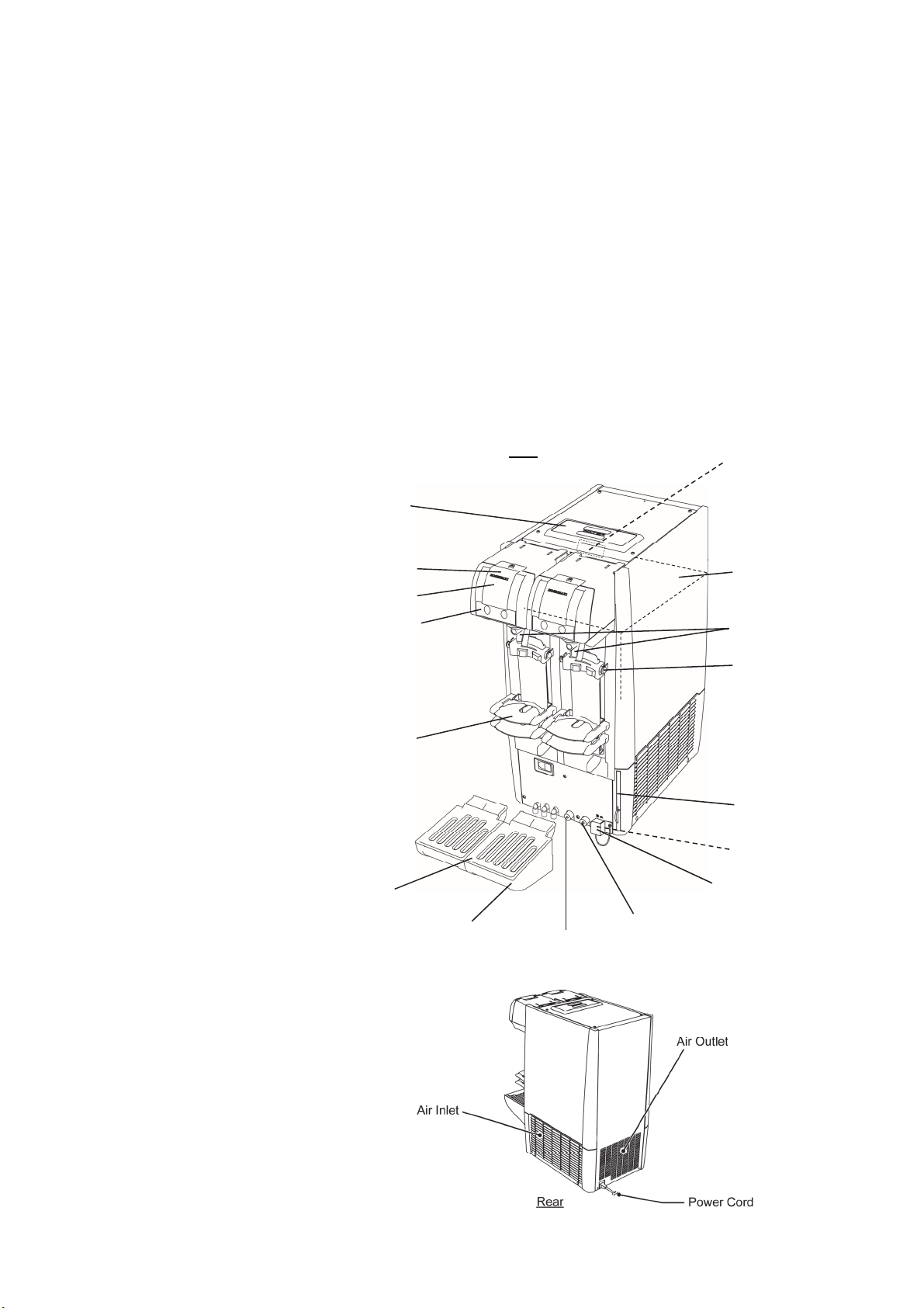
2. CONSTRUCTION --------------------------------------------------------------------------------------------------------- 3
BEER CIRCUIT -------------------------------------------------------------------------------------------------------------- 3
FEATURES ------------------------------------------------------------------------------------------------------------------ 4
3. DIMENSIONS/SPECIFICATIONS --------------------------------------------------------------------------------- 5
(1) DIMENSIONS/SPECIFICATIONS ---------------------------------------------------------------------------------- 5
(2) DISPENSING PERFORMANCE ------------------------------------------------------------------------------------ 6
TECHNICAL INFORMATION
4. UNIT CONTROL ---------------------------------------------------------------------------------------------------------- 7
(1) GENERAL OPERATION ------------------------------------------------------------------------------------------ 7 - 9
5. AUTOMATIC DISPENSING CONTROL ---------------------------------------------------------------------- 10
(1) OPERATION PANEL ------------------------------------------------------------------------------------------------ 10
(2) SETTINGS ------------------------------------------------------------------------------------------------------------- 10
(3) INPUT/OUTPUT ------------------------------------------------------------------------------------------------------ 18
(4) TIMING CHART -------------------------------------------------------------------------------------------------- 19, 20
SERVICE INFORMATION
6. WIRING DIAGRAM --------------------------------------------------------------------------------------- 21
7. CIRCUITS --------------------------------------------------------------------------------------------------- 22
(1) REFRIGERATION CIRCUIT --------------------------------------------------------------------------------------- 22
(2) BEER CIRCUIT ------------------------------------------------------------------------------------------------------- 22
8. ERROR DIAGNOSIS -------------------------------------------------------------------------------------
23
9. SERVICE DIAGNOSIS ----------------------------------------------------------------------------------------- 24 - 44
(1) BEER IS NOT COLD
(2) NO BEER IS DISPENSED
(3) BEER WILL NOT STOP
(4) BEER TAP KEEPS DRIPPING BEER
(5) UNDERFOAMING
(6) OVERFOAMING
(7) LARGE BUBBLES
(8) BEER TASTES STRANGE (WATERY)
(9) CYLINDER RUNS OUT OF GAS EASILY
(10) COOLING WATER MIXED WITH BEER COMES OUT OF OVERFLOW PIPE ON UNIT FRONT
(11) BEER TAP JOINT LEAKS BEER
(12) UNIT LEAKS WATER
(13) ABNORMAL NOISE
(14) BURNING SMELL
(15) AFTER UNIT IS TURNED ON, REFRIGERATION CIRCUIT CLICKS EVERY 3 - 5 MINUTES
CONDENSER FAN MOTOR IS RUNNING, BUT BEER IS NOT COLD
(16) MAIN POWER SUPPLY EARTH LEAKAGE CIRCUIT BREAKER TRIPS
(17) UNIT IS TURNED ON, BUT CONDENSER FAN MOTOR WILL NOT RUN
(18) INSTRUCTIONS FOR HANDLING CONTROLLER BOARD
(19) THERMISTOR SERVICE DIAGNOSIS
(20) BEER WILL NOT STOP

(21) DISPENSED AMOUNT IS DIFFERENT FROM PRESET AMOUNT
(22) MOTOR WILL NOT OPERATE NORMALLY
(23) DISPLAY SHOWS ERROR
(24) OPERATION PANEL UNIT WILL NOT GO DOWN COMPLETELY
(25) OPERATION PANEL UNIT GOES DOWN, BUT DISPENSE BUTTON WILL NOT LIGHT UP
WITH “OFF” DISPLAYED
(26) BEER REMAINS IN KEG, BUT SOLD OUT LAMP LIGHTS UP
NO BEER REMAINS IN KEG, BUT SOLD OUT LAMP WILL NOT LIGHT UP
(27) ADJUSTMENT OF PLATFORM AND REED SWITCH (FOR MUG SIZE DETECTION)
10. PARTS REPLACEMENT ------------------------------------------------------------------------- 45 - 49
11. CONTROLLER BOARD REPLACEMENT -------------------------------------------------------- 50
(1) CONTROLLER BOARD -------------------------------------------------------------------------------------------- 50
(2) OPERATION BOARD ----------------------------------------------------------------------------------------------- 51
(3) SENSOR BOARD ---------------------------------------------------------------------------------------------- 52 - 54
12. DISASSEMBLING AND ASSEMBLING VALVE SHAFT ------------------------------------------- 55
(1) REQUIRED TOOLS AND PARTS -------------------------------------------------------------------------------- 55
(2) DISASSEMBLING ---------------------------------------------------------------------------------------------- 56 - 59
(3) ASSEMBLING --------------------------------------------------------------------------------------------------------- 59
(4) NOTES ------------------------------------------------------------------------------------------------------------------ 59
13. MAKING AND SUPPLYING COOLING WATER ------------------------------------------------------- 60
(1) HOW TO MAKE COOLING WATER ----------------------------------------------------------------------------- 60
(2) COOLING WATER SUPPLY -------------------------------------------------------------------------------------- 61

1
GENERAL INFORMATION
1. SAFETY INSTRUCTIONS
The following instructions contain important safety precautions and should be strictly
observed. The terms used here are defined as follows:
WARNING: There is a possibility of death or serious injury to the service person and a
third party or the user due to improper service operations or defects in
serviced products.
CAUTION: There is a possibility of injury to the service person and a third party or the
user or damage to their property* due to improper service operations or
defects in serviced products.
* The term “damage to their property” here refers to extensive damage to household effects,
houses and pets.
WARNING
1. Always ask the user to keep children away from the work area. They may be injured by
tools or disassembled products.
2. When there is no need to energize the unit during disassembly or cleaning, be sure to
unplug the unit or disconnect the main power supply before servicing the unit to prevent
electric shocks.
3. If the unit must be energized for inspection of the electric circuit, use rubber gloves to
avoid contact with any live parts resulting in electric shocks.
4. Keep the following in mind when servicing the refrigeration circuit:
(1) Be sure to recover the refrigerant. Do not discharge it into the atmosphere. It will
affect the environment.
(2) Check for any flames in the vicinity, and ensure good ventilation.
(3) If the refrigerant should leak in servicing, immediately put out any fire used in the
vicinity.
(4) When unbrazing the refrigeration circuit connections, check that the circuit is
completely evacuated. The refrigerant may produce a poisonous gas when coming
in contact with an open flame.
(5) Do not braze in an enclosed room to prevent carbon monoxide poisoning.
(6) In case of a refrigerant leak, locate and repair the leaking part completely before
recharging the refrigerant and checking for further leaks. If the leaking part cannot
be located, be sure to check again for further leaks after recharging the refrigerant.
Leaked refrigerant may produce a poisonous gas when coming in contact with an
open flame of a gas cooking stove or a fan heater.

2
(7) Before servicing, check the surface temperature of the refrigeration circuit to
prevent a burn.
5. Keep the following in mind when making electrical connections:
(1) Check for proper grounding connections, and repair if necessary to prevent electric
shocks.
(2) Always use service parts intended for the applicable model for replacement of
defective parts. Use proper tools to secure the wiring. Otherwise abnormal
operation or trouble may occur and cause electric leaks or fire.
(3) Check for proper part installations, wiring conditions and soldered or solderless
terminal connections to avoid fire, heat or electric shocks.
(4) Be sure to replace damaged or deteriorated power cords and lead wires to prevent
fire, heat or electric shocks.
(5) Cut-off lead wires must be bound using closed end connectors or the like, with their
closed ends up to avoid entrance of moisture that could lead to electric leaks or fire.
(6) After servicing, always use a megohmmeter (500V DC) to check for the insulation
resistance of at least 1 megohm between the live part (attachment plug) and the
dead metal part (grounding terminal).
(7) Do not service the electrical parts with wet hands to prevent electric shocks.
(8) The capacitors used for the compressor and other components may be under high
voltage and should be discharged properly before servicing.
CAUTION
1. After servicing, follow the instructions below:
(1) Check the drain connections for water leaks to prevent possible damage to the
user’s property.
(2) Always check the unit for proper operation before finishing services.
(3) Be sure to reassemble the parts completely. Loose assembly of such parts as
control box cover may cause entrance of vermin resulting in a short circuit between
terminals and possible ignition.

3
2. CONSTRUCTION
BEER CIRCUIT
Beer dispensing system
1) Beer is delivered from the keg to the unit by CO2 gas pressure.
2) Beer is chilled by going through the beer coil.
3) Move the beer tap lever toward you to dispense cold beer.
4) Push the beer tap lever toward the unit to dispense creamy foam.
Beer chilling system
1) The compressor pushes refrigerant out.
2) The condenser exchanges heat.
3) The temperature of the evaporator decreases to freeze water in the cooling water tank.
4) Beer is chilled by going through the beer coil inside the cooling water.
5) To cool beer efficiently, the agitator motor always agitates water inside the cooling water tank to
increase thermal conductivity.
Bee
r
Foam
Lever
Beer ta
p
Regulator
(Pressure
adjustment)
CO2 gas
cylinder
Cooling water
Ag
itator motor
Beer coil
Ice
Evaporator
Heat exchange
Condenser fan
Condenser
Compressor
Beer keg
Beer

4
FEATURES
This unit automatically dispenses a preset amount (time) of liquid or foam when a button is pressed.
1) Automatic dispensing (portion control) is available by a single button operation.
2) Two different mug sizes are available by changing the mug location.
3) Two different mug sizes are automatically detected by changing the mug location.
4) The pressure reducing valve is manually adjusted.
5) The beer amount is easily adjustable by the front operation panel.
6) Manual dispensing option by beer tap operation is also available.
7) The unit is all driven by electric motors not by air.
8) Two kegs can be connected in parallel.
9) The beer taps are easily removable.
10) The air filter is removable from
the front of the unit.
Platform (Accessory)
Panel Cove
r
Drain Pan (Accessory)
Grille (Accessory)
Beer Inlet (Left)
Water Tank
Water Level Line (Label)
Beer Tap
O
p
eration Panel
Operation Panel Unit
Drain Outlet
Drain Cover
A
ir Filte
r
Tank Cove
r
Front
Plate Holde
r
Beer Inlet (Right)

5
3. DIMENSIONS/SPECIFICATIONS
(1) DIMENSIONS/SPECIFICATIONS

6
0
2
4
6
8
10
0 306090120
Dispensing Temp [ºC]
48.3L 10.2L
0
2
4
6
8
10
120 150 180 210 240
Dispensing Temp [ºC]
Dispensing Time [min]
10.2L 10.2L
1.4L
Standby Time Standby Time
Standby Standby Time Standby Time
(2) DISPENSING PERFORMANCE
Power supply: 220-240V 50Hz
Ambient/keg temp: 30°C
Gas pressure: 0.35MPa
Load: Four 20L beer kegs
Mug: 435mL
Stop dispensing at 8°C or higher dispensing temp --> Resume dispensing at 1°C or higher water
temp
Total amount dispensed: approx. 78L

7
TECHNICAL INFORMATION
4. UNIT CONTROL
(1) GENERAL OPERATION
a. Normal operation
When the power supply is turned on, one of the lamps on the operation panel lights up and
the compressor, condenser fan motor and agitator motor start.
• When the ice making sensor (long electrode) detects sufficient ice storage, the compressor
and condenser fan motor stop.
• When the ice making sensor (short electrode) detects insufficient ice storage, the
compressor and condenser fan motor restart.
• Repeat the above operations until the power supply is turned off.
• The condenser fan motor runs intermittently at low ambient temperatures (see “c.
Condenser fan motor low temperature control” for details).
[Timing chart]
2) Insufficient ice storage, short
electrode end exposed to water
No ice
Power supply (220-240V AC)
Controller board
(Compressor, condenser fan motor)
A
gitator moto
r
Ice storage
and electrode
Power on
1) Sufficient ice storage, long
electrode covered with ice
Long electrode
Short electrode
Electrode (front)
Ice Cooling wate
r
Ice Cooling water
1) Sufficient ice storage,
long electrode covered
with ice
2) Insufficient ice storage,
short electrode end
exposed to water
Repeat 1) and 2)
Ice storage and electrode

8
b. Electrode setting for hard water conditions
The electrode setting is adjustable by the setting mode “A05”.
c. Condenser fan motor low temperature control
When ambient temperature is low, the control ensures ice forming on the evaporator inside
the water tank.
1) When ambient temperature is below 10°C (condenser outlet temperature below 13°C), the
condenser fan motor stops to raise the condenser temperature to prevent refrigerant
liquefaction.
2) The condenser fan motor restarts when the condenser outlet temperature reaches 50°C or
10 minutes have passed since the compressor started.
3) The condenser fan motor keeps running until ice forming completes (compressor stops)
even if the condenser outlet temperature goes down below 13°C.
Condenser outlet
temperature
Compressor
Fan motor
Max. 10min
[During pull-down]
50°C
13°C
[During control]
Condenser outlet
temperature
Compressor
Fan motor
Max. 10min Max. 10min
50°C
13°C

9
d. Compressor protection when condenser fan motor is locked
When the condenser fan motor is locked, the compressor stops to prevent pressure rise in the
refrigeration circuit.
1) When the condenser fan motor is locked during operation and the condenser outlet
temperature reaches 75°C, the compressor stops.
2) The compressor restarts when the condenser outlet temperature goes down below 55°C
and 20 minutes have passed since the compressor stopped.
3) The above process is repeated until the condenser fan motor is unlocked.
* Even when the condenser outlet temperature reaches 75°C, only the compressor stops and
the condenser fan motor output stays on.
e. Status indication
Use the check mode “C04” to check the operational status of each component.
f. Error indication
When the condenser thermistor error (temperature below -20°C or above 90°C) occurs, the
error code “E51” appears in the display. The fan motor low temperature control (c) and the
compressor protection (d) are not available.
g. Condenser thermistor
Detection range: -20 to 90°C
Open circuit or short circuit when out of the above range.

10
5. AUTOMATIC DISPENSING CONTROL
(1) OPERATION PANEL
(2) SETTINGS
a. Overview
Liquid Button
[In ready mode]
Press and hold to dispense liquid
[In flush mode]
Press once to dispense liquid.
Press again to stop.
Dispense Button
(Dispense Lamp)
Lights up when the dispenser is In the
ready mode.
[Press once]
Automatically dispenses the preset
amount of beer.
[Press and hold]
Makes the automatic dispensing
settings available while in the setting
mode.
Flush Button
Switches between the ready mode
and flush mode.
Set Button
[Press once]
Switches between the setting mode
and ready mode (dispense lamp
flashes rapidly).
[Press and hold]
Used to make user settings (“U__” on
display).
Set Lamp
Lights up when the dispenser is in
the setting mode.
Display
Indicates number of mugs
and so on.
Ready mode Flush mode (after end of operation)
Setting mode (beer amount)
User settings (make adjustments, check logs)
Check mode (check conditions)
Adjust mode (change settings)
Service
engineer
User
Operation Panel
Foam Button
[In ready mode]
Press and hold to dispense
foam.
[In flush mode]
Press once to dispense foam.
Press again to stop.
Stop Button
[Press once]
Manually stops the beer tap or
platform operation.
[Press and hold]
Reset the display indication
(e.g. number of mugs)
Flush Lamp
Lights up when the dispenser is in
the flush mode.
S
old
O
ut Lamp
Lights up when the keg becomes empty.

11
b. User Setting Example (checking log of number of mugs)
Staff
Reset number of mugs (press and hold stop button
for 3 sec) when replacing kegs.
e.g.
- In operation -
2) Dispense automatically (real-time number of
mugs on display)
* Smaller/larger mug indication switches when
platform is changed.
3) End of 1st keg (display: 30 smaller mugs, 20
larger mugs)
4) Press and hold stop button for 3 sec to reset
number of mugs
--> Connect new keg and resume automatic
dispensing
5) End of 2nd keg (display: 27 smaller mugs, 21
larger mugs)
6) Reset number of mugs --> Resume automatic
dispensing
7) End of 3rd keg (display: 32 smaller mugs, 18
larger mugs)
8) Reset number of mugs --> Resume automatic
dispensing
9) Operation ends halfway through 3rd keg
(display: 7 smaller mugs, 5 larger mugs)
10) Clean in flush mode
Administrator
- Initial setting -
1) Set user setting (U01) to “Number of mugs”.
- After end of operation -
11) Check mug number log by user setting (U02)
Smaller: 7 --> 32 --> 27 --> 30 descending order
Larger: 5 --> 18 --> 21 --> 20 descending order
* Display log for latest 5 kegs.
12) Check number of keg replacements by user
setting (U04)
“3” on display if keg has been replaced 3 times,
that is, 3 kegs have been used today.
Press and hold stop button for 3 sec to reset to
“0”.
13) Check number of flush cycles by user setting
(U03)
“1” on display if 1 flush cycle has run.
If “10” is on display after 10 days, 1 flush cycle
per day has run.
Press and hold stop button for 3 sec to reset to
“0”.

12
c. User Settings – The user can adjust these settings.
To enter the setting mode:
Press and hold the set button for 3 seconds.
To enter the dispensing mode:
With “U_ _” on the display, press and hold the set button for 3 seconds. The dispensing mode is
also resumed if no operation is performed for more than 1 minute.
Item Description Default Setting
Range
U01
Digital display
(in dispensing
mode)
0: No indication
1: Number of mugs (*)
* Number switches between the larger and smaller mugs when
the mug setting is changed.
* To reset, press and hold the stop button for 3 seconds.
0 0 to 1
U02 Log of number
of mugs
Log of number of mugs for each reset in descending
order
* Log is indicated in turn for each keg replacement by “U04”.
* Log is indicated for both larger and smaller mugs when the
mug setting is changed.
* To reset all the current and past logs, press and hold the stop
button for 3 seconds. This reset is not counted for “U04”. (*1)
0 Up to
5 logs
U03 Number of flush
cycles
Number of flush cycles performed
* A flush cycle consists of liquid button operation (total 10
seconds) + foam button operation (total 3 seconds) in the
flush mode except when no automatic dispensing action is
made during the cycle.
* To reset, press and hold the stop button for 3 seconds.
0 0 to
9999
U04
Number of keg
replacements
(reset
frequency)
Reset frequency for number of mugs (*2)
* Keg replacement is counted every time the number of kegs is
reset by the stop button operation.
* To reset, press and hold the stop button for 3 seconds.
0 0 to
9999
U05 Dispense lamp
brightness Adjustment of dispense lamp brightness 6 1 to 8
U06
Dispense lamp
flashing
duration
Adjustment of dispense lamp flashing duration after
completion of dispensing
* The dispense lamp flashes to prevent another mug is placed
while foam is still dripping.
* Automatic dispensing action is not available while the lamp is
flashing.
1 0 to 10

13
U07 Sold out sensor
setting
0: Setting A (mainly beer) / threshold: 2.2V
1: Setting B (mainly cocktail) / threshold: 2.5V
2: Setting C (mainly cocktail) / threshold: 2.8V
3: Setting D (optional) / threshold: optional
* The setting depends on the brand of beverage to dispense.
Check with your dealer/supplier.
0 0 to 3
U08 Self mode
setting
0: No
1: Yes (no button operation is available except
dispense/stop button)
* The self mode is reset when the manual dispensing mode is
selected (by lifting up the operation panel unit). To resume
the self mode, switch to the automatic dispensing mode (by
pulling down the operation panel unit) and press the dispense
button.
0 0 to 1
U09 Mug tilting
operation
0: Yes (mug is tilted while beer is being dispensed)
1: No (mug is kept upright while beer is being dispensed) 0 0 to 1
U10 Reset number
of mugs
0: Manual
1: Manual or when sold out sensor detects
* To reset manually, press and hold the stop button for 3
seconds.
0 0 to 1
U90 Reset settings
Initialize only the user settings
* To initialize, with “1” shown on the display, press and hold the
stop button for 3 seconds.
* If the settings are updated, “U90” appears on the display. If
not updated, “0” appears again.
0 0 to 1
*1: When “U10” is set to “1”, only the current log will be reset.
*2: When “U10” is set to “1”, only the number of sold out will be counted. The number of 3-second
stop button operation with the number of mugs or “U02” on the display will not be counted.

14
d. Check Mode – Service engineers use this mode to check the unit condition.
To enter the check mode:
Press and hold the flush and stop buttons for 3 seconds.
To enter the dispensing mode:
Press and hold the set button for 3 seconds, or press the flush and stop buttons.
The dispensing mode is also resumed if no operation is performed for more than 10 minutes.
Item Description Default Display
Range
C01 Check version
(main board) Display main board version – –
C02
Check version
(operation
board)
Display operation board version – –
C03 Error log
Display log of errors and canceled dispensing
operations
* Displayed in descending order
* Repeated errors are also recorded
–
E_ _
F_ _
(20 logs)
C04
Operation
monitor
(real-time)
Digitally display ON/OFF status of each input/output
1: Platform in lowest position
2: Platform in highest position
3: Beer tap slider in liquid dispensing position
4: Operation panel unit in manual mode
5: Beer tap slider in foam dispensing position
6: Sold out
7: Beer tap in center position
8: Larger mug detection (reed switch)
11: Stop button
12: Liquid button
16: Foam button
17: Dispense button
13: Set button
15: Flush button
21: Compressor
22: Fan motor
31: Pressure detection (set pressure ± 0.02MPa)
32: Pressure regulating valve operation
C05
Sold out
monitor
(real-time)
Display detected voltage (V) real-time (average per 0.45
sec) – –
C06
Condenser
thermistor
(real-time)
Display condensing temperature real-time (°C) – -20 to
90

15
C07
Ice storage
detection
[long]
(real-time)
Display electrode detected value real-time – –
C08
Ice storage
detection
[short]
(real-time)
Display electrode detected value real-time – –
C50 Model setting Check model setting
1: Standard model 1 –

16
e. Adjust Mode – Service engineers use this mode to adjust the settings.
Note: Do NOT make changes in normal operation.
To enter the adjust mode:
Press and hold the set and stop buttons for 3 seconds.
To enter the dispensing mode:
Press and hold the set button for 3 seconds, or press the set and stop buttons.
The dispensing mode is also resumed if no operation is performed for more than 10 minutes.
Item Description Default Display
Range
A01
Mug tilt angle
* For use of
pitcher, etc.
Set platform tilt angle 120 50 to
120
A02 Manual beer tap
slider operation
Manual operation of beer tap slider is available by
liquid/foam button
Same segment as operation monitor lights up while
liquid/foam button is pressed
– –
A03 Reset self mode 0: Priority on “U08” setting
1: Reset (“U08” to 0) 0 0, 1
A04
Display canceled
dispensing
operation
(F1, F2, F3, F4)
0: Not display (but recorded in error log)
1: Display
* F1: stop button, F2: manual, F3: sold out, F4: other
* Available until next dispensing operation
0 0, 1
A05 Electrode setting
for cooling water
0: Japan - freezing 2.50, melting 2.29
1: Other countries - freezing 2.34, melting 1.97
2: Variable (see “A06”, “A07”)
* Both sides cannot be operated at the same time
0 0, 1, 2
A06
Electrode
threshold for
cooling water
(freezing)
Electrode threshold for cooling water (freezing)
* Check only if “A05” is set to 0 or 1
* Adjustable if “A05” is set to 2
(2.34)
0.60 to
3.10 /
0.01
A07
Electrode
threshold for
cooling water
(melting)
Electrode threshold for cooling water (melting)
* Check only if “A05” is set to 0 or 1
* Adjustable if “A05” is set to 2
(1.97)
0.60 to
3.10 /
0.01
A08 Sold out sensor
threshold setting
Sold out sensor threshold setting (V) when “U07” is
set to 3 2.95
0.60 to
3.10 /
0.01
A30 Coin mechanism
setting Not in use 0 0, 1, 2

17
A31 Coin mechanism
type 1 Not in use 0 0, 1
A32 Coin mechanism
type 2 Not in use 0 0, 1
A40
Foam button
operation to
reset sold out
Duration to press and hold foam button to cancel
sold out
* Need to press foam button once even if set to 0
sec
0 0 to 20 /
1
A80 Adjust mode Not in use 0 0 to
9999 / 1
A90 Reset settings
(user settings) Same as “U90” 0 0, 1
A91
Reset settings
(check mode &
adjust mode)
Initialize check mode and adjust mode settings to
defaults
With “1” on display, press and hold stop button for 3
sec --> “A91” on display
* “C03” error log will also be deleted
* “U02” to “U04” logs and beer amount setting will
not be deleted
0 0, 1
A01: The platform tilt angle is adjustable to prevent a mug from touching the beer tap.
A02: As mentioned in (24) of “9. SERVICE DIAGNOSIS”, if the beer tap slider does not go back to
the center position to fit the tap handle, the motor must be removed to move the beer tap
slider back to the center position. While “A02” is selected, press the liquid/foam button to
move the beer tap slider to any position without removing the motor. Not used in normal
operation.
A03: Normally, the self mode is reset by lifting up the operation panel unit. If it cannot be moved,
use “A03” to reset the self mode.
A04: The administrator can check the dispensing operations canceled, for example, by customers
in the self mode.
A05 to A07:
The ice storage condition is checked by the electric conductivity of cooling water. The
threshold of the electric conductivity is adjustable. Not used in normal operation.
A08: The setting D of the user setting (U07) is adjustable.
A30 to A32:
Not used in normal operation.
A40: After keg replacement, if beer foam is not led to the beer tap enough, beer may splash out of
the beer tap. To prevent this, the foam button must be pressed and held for this duration to
cancel the sold out condition.
* The longer the duration is adjusted, the more beer is wasted to lead beer foam to the beer
tap. Customer approval is required before adjustment.
A80: Not in use.
A90, A91:
To leave the settings as they are and delete the logs (U02, U03, U04, C03) only, press and
hold the set and flush buttons, turn off the breaker, and turn it back on. The beer amount
setting will not be deleted.
Other manuals for DBF-AS65WE-EU
1
Table of contents
Other Hoshizaki Dispenser manuals
Popular Dispenser manuals by other brands

AUTOMATED EQUIPMENT
AUTOMATED EQUIPMENT AFD-200 Equipment manual

FM
FM HARBIL NSC50 Operating and instruction manual

tatsuno
tatsuno OCEAN TOWER Series Installation and user manual

Kohler
Kohler 1400976-2-A installation instructions

Bradley
Bradley 6322 Care and maintenance

Nordson EFD
Nordson EFD Ultimus I instructions