ENGLISH
3
2. When using a single compressor
refrigeration unit that is installed in a remote
location, ensure that it is adequately
protectedagainstlow ambienttemperatures
(capacity controls/crankcase heating), oil
returnwheretheicemakerisbelowtheheight
of the compressor (suction risers/oil traps/
oil separators) and liquid refrigerant return
where the icemaker is above the height of
the compressor (suction accumulator).
Always check the compressor
manufacturer’sguidelines.
3. An electrical link/connection between the
icemaker and compressor system is NOT
necessary. Where a multi compressor rack
system is used, the icemaker’s internal
controls will close the electrically operated
solenoid valves to stop ice production.
Where a single remote compressor is used,
thismust be fittedwith a low pressuresafety
switch to stop the compressor at approx.
0.5 bar suction pressure as the solenoid
valve’s closing will result in the compressor
pumpingdown.
8) After completing all the refrigeration tubing
connections, the pipe work should be leak tested,
evacuatedand vapour charged with R404A.
9) Open the ball valve to ensure the ice production
capacity when the compressor refrigeration
capacity is less than 1.6kW at an evaporating
temperature of -18°C, condensing temperature
43°C, return gas temperature 5°C, liquid
temperature43°Candambienttemperature35°C.
Close the ball valve to protect the icemaker when
the compressor refrigeration capacity is 1.6kW
or more.
10) The refrigeration connections are now complete.
Proceedto sections 4 and 5to continue withother
serviceconnectionrequirementsbeforecompleting
section 6, the start-up procedure.
11) Refit the Side and Top Panels in their correct
positions.
4. ELECTRICAL CONNECTIONS
WARNING
THIS APPLIANCE MUST BE EARTHED
This icemaker requires an earth that meets the
national and local electrical code requirements.
To prevent possible severe electrical shock to
individuals or extensive damage to equipment,
install a proper earth wire to the icemaker.
Disconnect the main power supply before any
maintenance, repairs or cleaning is undertaken.
* This icemaker should not be installed:
a) Where the power supply is not within the range
of 220 - 240V.
b) Wheretheicemakercannotbeconnecteddirectly
into its own power supply without using an
extension cord or sharing a receptacle.
* Usually an electrical permit and services of a
licensed electrician are required.
* If the supply cord and/or the plug should need to be
replaced, it should only be done by a qualified
serviceengineer.
* In accordance with the requirement of the IEC
standard, the maximum permissible system
impedance(Zmax)attheinterfacepointofthepower
supply to be connected with this icemaker must be
0.17+j0.10 ohm (FM-600/FMN-440) or
0.2908+j0.18175 ohm (FM-481). Determine in
consultation with the supply authority, if necessary,
that the icemaker is connected only to a supply of
0.17+j0.10 ohm (FM-600/FMN-440) or
0.2908+j0.18175 ohm (FM-481) or less.
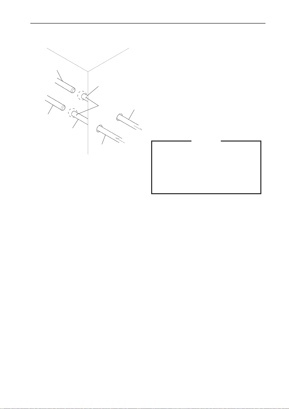
Fig. 6
1/2” ID
Suction Line
Liquid Line
1/4” ID
Expand
Suction Line
Liquid Line
Icemaker
pipe). Equivalent pipe lengths that exceed
20 m should be increased in size to 3/8”
OD liquid line and 5/8” OD suction line.


 User manual")