4 Operating modes
The units have the following operating modes:
■Supply air speed 2 (only TopVent®MH, MC, MHC)
■Supply air speed 1 (only TopVent®MH, MC, MHC)
■Recirculation
■Recirculation speed 1
■Standby
The TopTronic®C control system regulates these operating
modes automatically for each control zone in accordance
with the specications in the calendar. The following points
also apply:
■The operating mode of a control zone can be switched
over manually.
■Each TopVent®unit can operate individually in a local
operating mode: O, Supply air speed 2, Supply air speed
1, Recirculation, Recirculation speed 1 (depending on the
unit type)
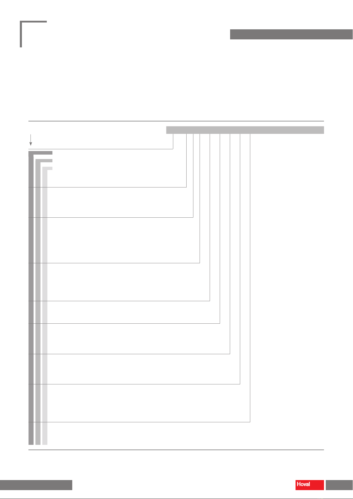
Code Operating mode Description
SA2 Supply air speed 2
The unit blows fresh air into the room. The fresh air ratio is adjustable.
Heating/cooling is controlled according to the heat/cool demand. The room
temperature set value day is active. The unit operates at speed 2 (high air flow rate).
Fan .................................. speed 2
Fresh air damper.............. 10 % open 1)
Heating/cooling ................ on 2)
1) Percentage is adjustable
2) Depending on heat or cool demand
SA1 Supply air speed 1
The same as SA2, but the unit operates at speed 1 (low air flow rate)
Fan .................................. speed 1
Fresh air damper.............. 10 % open 1)
Heating/cooling ................ on 2)
1) Percentage is adjustable
2) Depending on heat or cool demand
REC Recirculation
On/Off operation: During heat or cool demand, the unit draws in room air, heats
or cools it and blows it back into the room. The room temperature set value day is
active.
Fan .................................. speed 1 / 2 1)
Fresh air damper.............. closed
Heating/cooling ................ on 1)
1) Depending on heat or cool demand
DES ■Destratication:
To avoid heat build-up under the ceiling, it may be appropriate to switch on the
fan when there is no heat demand (either in permanent operation or in on/off
operation depending on the temperature stratication, as desired).
Fan .................................. speed 2
Fresh air damper.............. closed
Heating/cooling ................ off
REC1 Recirculation speed 1
The same as REC, but the unit operates only at speed 1
(low air flow rate)
Fan .................................. speed 1
Fresh air damper.............. closed
Heating/cooling ................ on 1)
1) Depending on heat or cool demand
DES ■Destratication:
The same as for REC, but the unit operates only at speed 1
Fan .................................. speed 1
Fresh air damper.............. closed
Heating/cooling ................ off
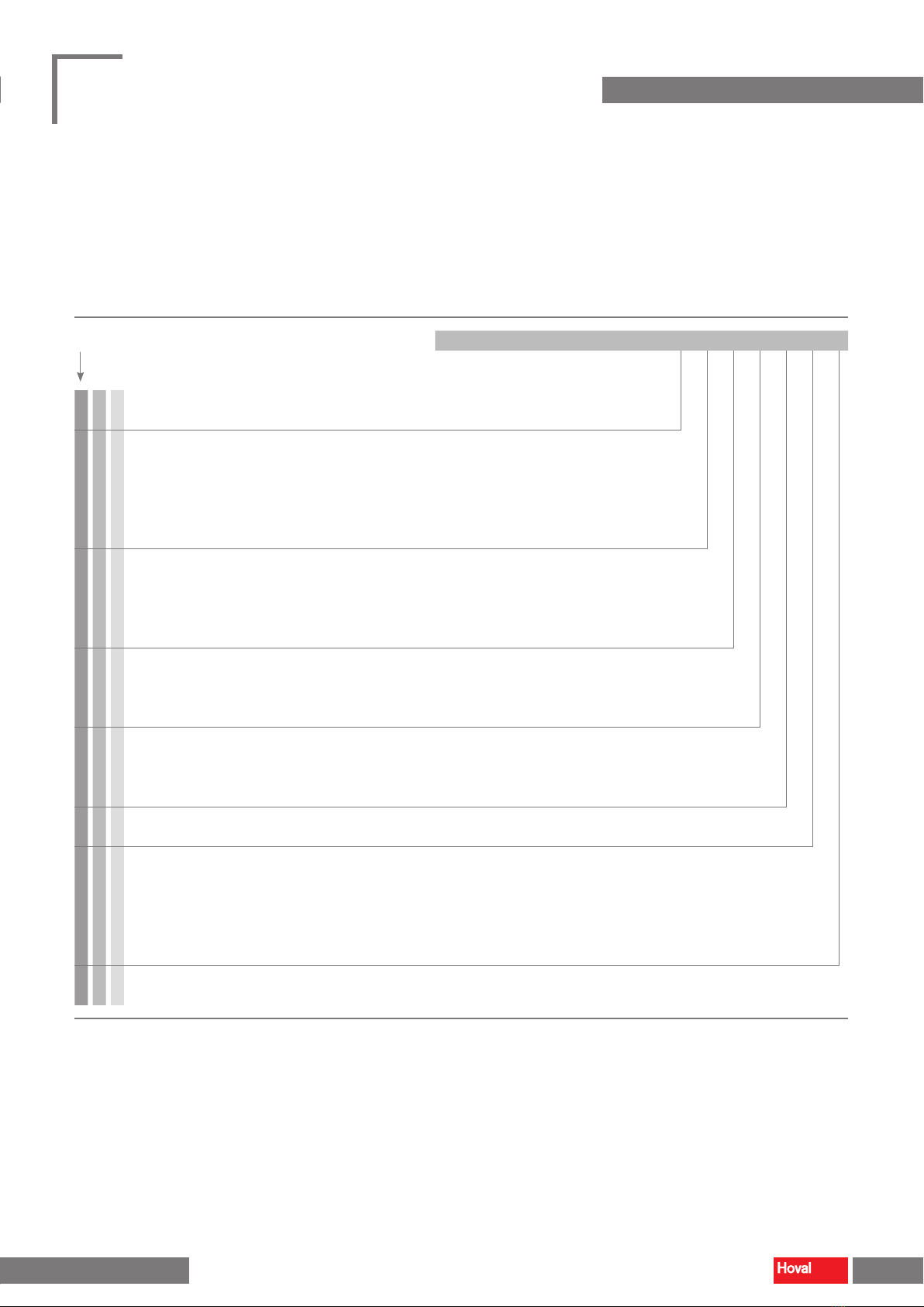
ST Standby
The unit is ready for operation. The following operating modes are activated if required:
CPR ■Cooling protection:
If the room temperature drops below the set value for cooling protection, the unit
heats up the room in recirculation operation.
Fan .................................. speed 2
Fresh air damper.............. closed
Heating ............................ on
OPR ■Overheating protection: (only cooling units)
If the room temperature rises above the set value for overheating protection, the
unit cools down the room in recirculation operation.
Fan .................................. speed 2
Fresh air damper.............. closed
Cooling............................. on
NCS ■Night cooling: (only TopVent® MH, MC, MHC supply air units)
If the room temperature exceeds the set value for night cooling and the current
fresh air temperature permits it, the unit blows cool fresh air into the room and
extracts warmer room air.
Fan .................................. speed 2
Fresh air damper.............. open
Heating/cooling ................ off
L_OFF Off (local operating mode)
The unit is switched off. Frost protection for the unit remains active.
Fan .................................. off
Fresh air damper.............. closed
Heating/cooling ................ off
–Forced heating (only TopVent® MH, MC, MHC supply air units)
The unit draws in room air, warms it and blows it back into the room.
Forced heating can be activated and set as required by the Hoval service technician.
For example, it is suitable for heating the hall before taking the control system into
operation or if the controller fails during the heating period.
Fan .................................. speed 2 1)
Fresh air damper.............. closed 1)
Heating ............................ on 1)
1) Adjustable by the Hoval service technician
Table 1: Operating modes
6 7
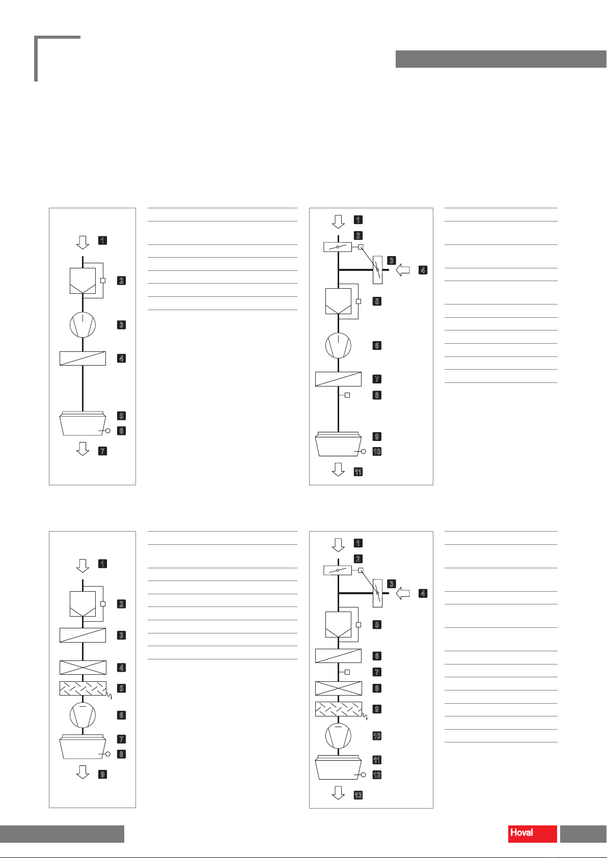
TopVent ®TH |TC |THC |MH |MC |MHC
Operating instructions
Construction and operation Operating modes
4 218 828-en-01