Howard Wright M9 TRANSFER User manual

INSTRUCTIONS FOR USE
M9TRANSFER

Instructions For Use Purpose
These instructions contain helpful information and important safety instructions for safe and proper operation and
servicing of the M9Transfer stretcher. Read it carefully and fully understand before operating or servicing the stretcher.
Standard Warranty
Thank you for purchasing your product from Howard Wright Limited.
Please refer to our website for our warranty terms:
• www.howardwrightcares.com
• www.howardwrightcares.co.uk
Howard Wright Limited’s Policy
Howard Wright Limited has a policy of continuous improvement and reserves the right to change product specifications
and information referred to in this document without notice.
All rights reserved.
No part of this publication may be reproduced without the prior written permission of Howard Wright Limited.
© Copyright – Howard Wright Limited, 2013.
This product shall be accepted and used in accordance with national requirements.
IMPORTANT: Any serious event should be reported by the user and/or patient to Howard Wright Limited, and
when within the European Union, the Competent Authority of the member state.
NOTE: In these instructions, the term patient refers to one who receives medical attention, care, or
treatment.
17 Paraite Road, Bell Block PO Box 2786
PO Box 3003, Fitzroy Taren Point,
New Plymouth, 4341 New South Wales
New Zealand 2229, Australia
T. +64 (6) 755 0976 T. 1800 120 727
F. +64 (6) 755 0908 F. 1800 120 717
Advena Limited. Tower Business
Centre, 2nd Flr., Tower Street,
Swatar, BKR 4013. Malta.
Advena Limited.
Pure Offices, Plato Close,
Warwick, CV34 6WE, UK.
UK
Responsible
Person
EC REP

M9 Transfer Instructions For Use (M999-19, Version 10, 2021-12) 1
CONTENTS
CHAPTER
1. INTRODUCTION......................................................................................................................................................................... 2
2. PRECAUTIONS...........................................................................................................................................................................4
3. ABBREVIATIONS, SYMBOLS & TERMINOLOGY............................................................................................................6
4. PART IDENTIFICATION ............................................................................................................................................................8
5. UNPACKING & COMMISSIONING .....................................................................................................................................9
6. OPERATION...............................................................................................................................................................................10
7. ACCESSORIES.........................................................................................................................................................................21
8. CLEANING .................................................................................................................................................................................27
9. PACKING FOR TRANSPORT OR STORAGE..................................................................................................................29
10. ELECTRIC CONTROL PROBLEM SOLVER................................................................................................................. 30
11. MAINTENANCE & SERVICING .........................................................................................................................................31
12. SPECIFICATIONS................................................................................................................................................................. 34
13. ELECTROMAGNETIC COMPATIBILITY .........................................................................................................................37
14. CONFORMITY....................................................................................................................................................................... 38
15. INDEX ....................................................................................................................................................................................... 39
PAGE

2 M9 Transfer Instructions For Use (M999-19, Version 10, 2021-12)
1.1 HOWARD WRIGHT LIMITED
Congratulations on choosing a Howard Wright Limited product. Established in the 1950’s, Howard Wright Limited
has built a reputation based on quality product and design innovation. Today Howard Wright Limited equipment is
found in healthcare institutions worldwide.
1.2 INTENDED USE
The M9 Stretchers are mainly used in assisting the diagnosis, monitoring, prevention, treatment and alleviation of
disease, or compensation for an injury or disability.
The M9 Stretchers are designed to be used by trained health professionals and, to a limited extent, members of
the public.
The M9 Stretchers are used generally within a hospital emergency department, day surgery clinic, X-Ray (M9 Trauma)
or throughout the hospital as a means of treatment for patients, resting and observation of patients and transporting
patients from one department or area to another.
The M9 Stretchers are intended to support adult patients aged 12 years and over with a minimum weight of 15kg.
The M9 Stretchers may accommodate one patient up to a weight not exceeding 250kg (including mass of mattress
and accessories).
1.3 TECHNICAL SUMMARY
1.3.1 VERSIONS
One version of the M9 Transfer stretcher is available:
• M9 Transfer (Horizontal siderails)
This stretcher is supplied with electric operation only.
Various options and accessories are available for the M9 Transfer stretcher. Please contact Howard Wright Limited
for more information.
1.3.2 CONSTRUCTION
Howard Wright Limited products are manufactured from high quality durable engineering materials including steel,
aluminium and stainless steel with a durable epoxy/polyester hybrid powder coated finish. High quality durable
engineering plastics including Nylon, ABS, TPR & Polypropylene are also used.
M9 Transfer stretchers have a LINAK control box. This uses mains power at 220-240 V AC (50-60 Hz) to operate
LINAK actuators at 24 V DC. An onboard sealed lead-acid battery provides power when mains power is not available
(e.g. when moving the stretcher). Control buttons are located on a remote handset for adjustment of the backrest,
deck height, deck tilt, legraise and an auto-contouring preset function.
1. INTRODUCTION

M9 Transfer Instructions For Use (M999-19, Version 10, 2021-12) 3
1. INTRODUCTION
1.4 APPLICATION ENVIRONMENT
The stretcher is only intended for use in these environments:
APPLICATION ENVIRONMENT 1:
Intensive/critical care provided in a hospital where 24 hour medical supervision and constant
monitoring is required and provision of life support system/equipment used in medical procedures is
essential to maintain/improve the vital functions of the patient.
APPLICATION ENVIRONMENT 2:
Acute care provided in a hospital or other medical facility where medical supervision and monitoring
is required and medical equipment used in medical procedures may be provided to help maintain or
improve the condition of the patient.
APPLICATION ENVIRONMENT 5
Outpatient (ambulatory) care, which is provided in a hospital or other medical facility, under medical
supervision where ME EQUIPMENT, is provided for the need of persons with illness, injury or
disability for treatment, diagnosis or monitoring
NOTE: This includes use in nursing homes, rehabilitation and geriatric facilities.
1.5 SAFE WORKING LOAD (SWL)
Maximum patient weight = SWL minus weight of accessories
1 x O2 cylinder = 12 kg
1 x IV pole = 1.2 kg
1 x PH pole = 6.1 kg
1 x Mattress = 12 kg
≈ 30 kg
MAXIMUM PATIENT WEIGHT = SWL - 30 kg
MAXIMUM SWL = 220 kg
NOTE: This is an indicative list. Other accessories can be used and the weight of these must be deducted.
220kg 250kgMAX
Figure 1. Safe Working Load

4 M9 Transfer Instructions For Use (M999-19, Version 10, 2021-12)
2.1 CONVENTIONS
The following conventions are used in this publication:
WARNING: Gives instructions or information intended to ensure the safety of the patient, caregiver and other
personnel.
CAUTION: Gives instructions or information intended to avoid damage to the stretcher or its accessories.
NOTE: Gives additional instructions or information intended to make the stretcher easier to use.
2.2 USER EDUCATION AND TRAINING
WARNING: If the patient suffers from disorientation, depression or similar then the electric functions should be
locked out to prevent the patient operating the stretcher.
OPERATOR: Must be trained in the use of the stretcher and fully understand the instructions for use.
PATIENT: Follow the hospital risk management policy. The patient must be capable and fully understand the
handset functions before they can operate the electric functions by themselves.
2.3 GENERAL WARNINGS & CAUTIONS
WARNING: Read and understand these instructions for use before using the stretcher.
WARNING: Adhere to the hospitals risk management policy when placing a patient on the stretcher.
WARNING: Leave the stretcher in its lowest position when the patient is unattended.
WARNING: Do not use the stretcher for cyclic or repetitive manipulations of the patient.
WARNING: If the stretcher is found to have sustained any damage it must be removed from use immediately.
WARNING: Ensure there is no risk of crushing or entrapment to the patient, other personnel, stretcher
components, or other objects when using the stretcher.
WARNING: Do not position the stretcher under any object.
WARNING: Residual current devices (RCD) are not supplied as standard with the stretcher. Consult with your
Biomedical Engineer/advisor concerning your RCD requirements.
WARNING: The stretcher is intended to support one patient at a time only.
WARNING: Do not connect the power cord if the plug or cord insulation is damaged. The power cord must be
replaced. However, the stretcher can still operate on battery
WARNING: The safe working load of the stretcher is 250kg (this includes the mass of the patient mattress and
any accessories).
WARNING: Do not allow people to sit on the backrest or legraise when it is in the raised position.
WARNING: Follow the cleaning and disinfection instructions.
WARNING: Only connect the stretcher to a mains supply with protective earth.
WARNING: Before using a mobile patient hoist, check underbed clearance.
2. PRECAUTIONS

M9 Transfer Instructions For Use (M999-19, Version 10, 2021-12) 5
WARNING: Do not use in an oxygen rich environment or any flammable gas environment.
WARNING: Do not modify any component or accessory without prior authorisation from Howard Wright Limited.
WARNING: Do not transport patients where the stretcher may become unstable
For example, inclines over 10 degrees.
WARNING: When routing cables from other equipment onto the stretcher, take precaution to avoid
the cables being squeezed between stretcher components.
WARNING: Always handle the power cord with care and keep it clear of any moving parts.
WARNING: Ensure the power cord and plug are always accessible.
WARNING: The supply plug is the only disconnection device.
CAUTION: Always stow the power cord and other equipment before transporting the stretcher.
CAUTION: The leg-raise panel must be physically supported when cleaning the underside.
2. PRECAUTIONS

6 M9 Transfer Instructions For Use (M999-19, Version 10, 2021-12)
3.1 ABBREVIATIONS
ABS Acrylonitrile Butadiene Styrene
AC Alternating Current
ACH Attendant Control handset
AS/NZS Australian/New Zealand Standard
CE European Conformity
CPR Cardiopulmonary Resuscitation
DC Direct Current
EEC European Economic Community
EMC Electromagnetic Compatibility
IEC International Electrotechnical Commission
IP Ingression Protection
ISM Industrial, Scientific and Medical
IV Intravenous
LH Low Height
PAT Portable Appliance Test
PE Polyethylene
PH Patient Help
POAG Potential Equalisation Terminal
PP Polypropylene
PREMA Pressure RElieving MAttress
PU Polyurethane
PVC Polyvinyl Chloride
RCD Residual Current Device
SN Serial Number
SWL Safe Working Load
TPR Thermoplastic Rubber
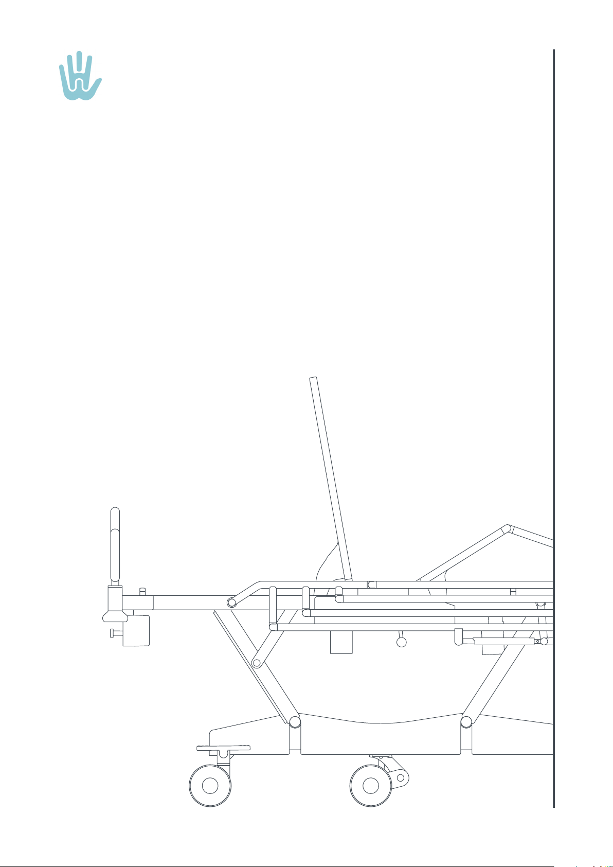
3.2 STRETCHER ORIENTATION TERMINOLOGY
NOTE: The terms head end, foot end, left and right used in this publication are referenced from the perspective
of a supine patient.
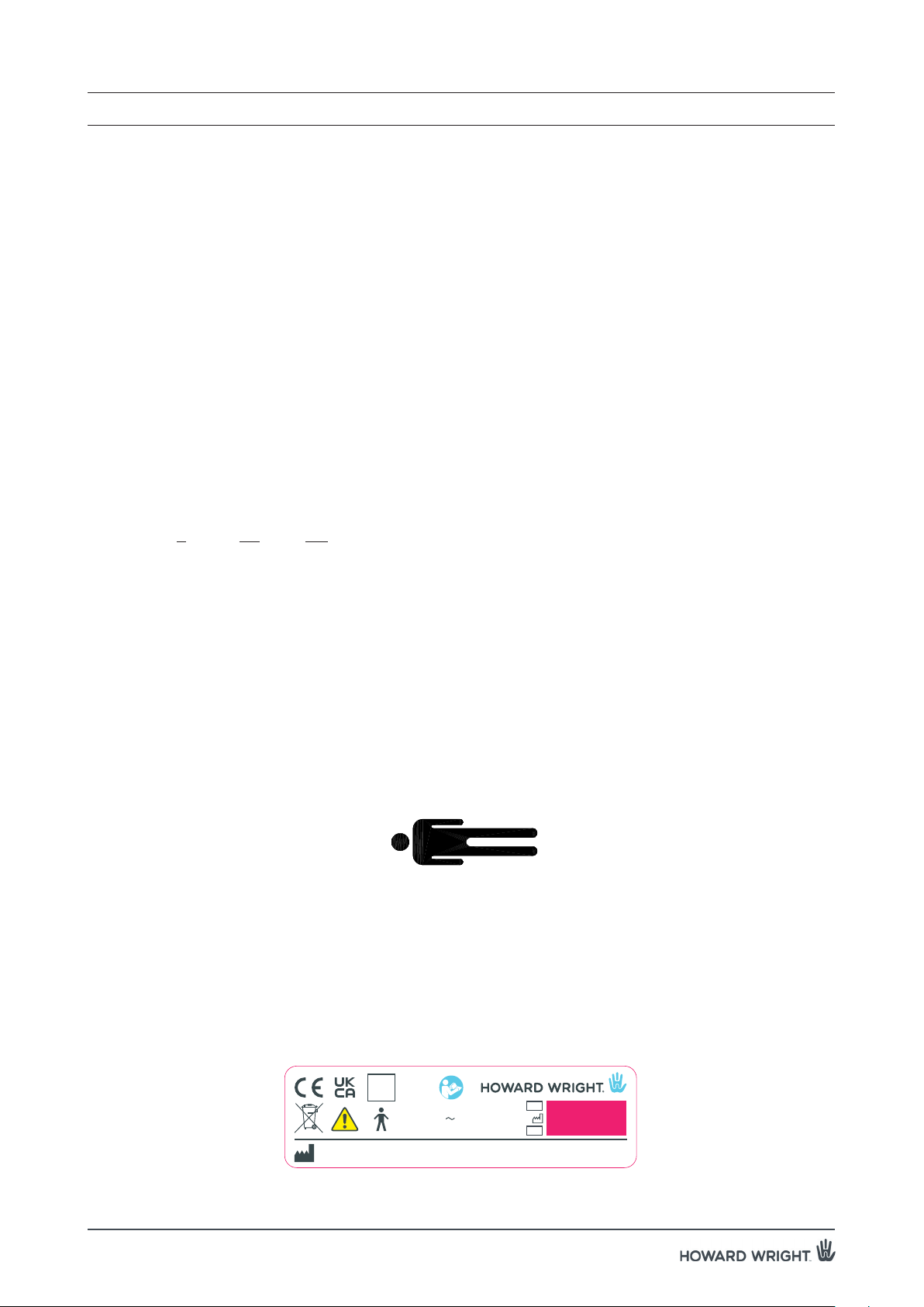
3.3 SERIAL NUMBER LABEL SYMBOLS
The serial number label is located at the foot end left side of the deck frame.
NOTE: The colour red is used for emergency controls and warning symbols. The brake pedal is red and
indicates the brake position.
Figure 2. Stretcher orientation terminology
3. ABBREVIATIONS, SYMBOLS & TERMINOLOGY
Right
Left
Foot end
Head end
Figure 3. Stretcher serial number label - M9 Transfer Stretchers
M930-06 REV E
Keep clear during backrest & CPR operation
Howard Wright Limited, 17 Paraite Road, Bell Block, New Plymouth, New Zealand.
Australia: 1800 120 727 New Zealand: 0508 751 751 UK: 0845 094 9894
Power Input: Max. 2.0A
220-240V 50-60Hz
Mode: Max. 2min/20min
220kg 250kgMAX
220kg 250kgMAX
Potential
Equalisation
Terminal
tneverpotnoitcnuftuokcolesU
ehtfotnemevomdednetninu
mroftalptroppussserttam
160mm
MAX 700mm
2000mm
Mandatory Mattress Size:
Howard Wright Limited, Paraite Road, New Plymouth, NEW ZEALAND
Part # 1:M930-06
Part # 2:
M9 TRANSFER LABEL SET
Description:
Parent Product: M9
Drawing Size: A2
Material:Rev
C
Colours:Pantone 637
Drawn
DAB
ChkdDate
17.05.21
New Artwork:
Adhesive:
Tooling: New Artwork / Use Knife 6891K1SETUP
Polycarb .175 Matt HP40
TA9474LE
Drawing Scale: 1:1
Grey White Background - matched to HWL powdercoat sample.
DIELINE
Permark UV 624
TRANSFER TRANSFER
Control Box Service
Do not use in oxygen rich environments
Class 1 Medical Electrical Equipment
Use lock out function to prevent unintended
movement of the mattress support platform
Protective earth conductor is fitted to the fixed
wiring. Ensure that the power and handset cords
are positioned so they cannot become damaged
during bed adjustment.
Keep plugged in
whenever possible
Power Input: Max. 2.0A
Mode: Max. 2min/20min
220-240V 50-60Hz
ECR763 - MD UKCA added
Note: Pink box is a clear window, no print colour.
Keep clear during backrest & CPR operation
tneverpotnoitcnuftuokcolesU
ehtfotnemevomdednetninu
mroftalptroppussserttam
IPX4
MD
AJB
EC REP
Advena Limited.
Tower Business Centre, 2nd Flr.,
Tower Street, Swatar,
BKR 4013 Malta.
Advena Ltd.
Pure Offices, Plato Close,
Warwick, CV34 6WE
United Kingdom.
UK
Responsible
Person
D DAB
15.06.21 ECR763 - EC REP added was seperate label. AJB
:
:
:
SN
#
D DAB
12.10.21 ECR763 - Symbols, 17 & UV653 added.
Permark UV653

M9 Transfer Instructions For Use (M999-19, Version 10, 2021-12) 7
3. ABBREVIATIONS, SYMBOLS & TERMINOLOGY
Warning.
IPX4
Ingression protection (IP) rating as per BS EN 60529:1992, specification of degrees
of protection provided by enclosures.
•The number (4) refers to the degree of “water ingression protection”
Indicates compliance with the applicable European requirements.
Type B applied part.
MD Indicates the product is a Medical Device.
WEEE, Waste Electrical and Electronic Equipment.
Read and understand the instructions for use (IFU) before using the stretcher.
Power Input: Input current (maximum), supply voltage range, supply frequency range.
~Alternating current.
Mode: The stretcher is intended for intermittent operation. The ratio of the operating time to the
sum of the operating time and ensuing time should not exceed that specified.
#Reference code (model number).
Date of manufacture.
Serial number.
Manufacturer.
European Authorised Representative.
3.4 OTHER SYMBOLS & TERMINOLOGY
220kg 250kgMAX
Maximum patient weight, kg.
220kg
250kg
MAX
Maximum safe working load (SWL), kg.
Warning: potential squeezing/shearing point.
Equipotentiality (potential equalisation).
Do not sit.

8 M9 Transfer Instructions For Use (M999-19, Version 10, 2021-12)
Figure 4. Part Identification - M9 Transfer stretcher
4.1 PART IDENTIFICATION - M9 TRANSFER STRETCHER
Potential equalisation
(POAG) terminal
Mattress
retainer
Legraise
Seat panelBackrest
Corner
socket Bed end
Deck
Corner buffer &
corner socket
Castor
Castor
pedal
Bogie
CPR
lever
Steer castor
Siderail
release
4. PART IDENTIFICATION
Siderail
Drainage
bag rail
Handset
Control
box
Area of applied part
5th wheel
Deck
stop
Accessory
mount rail
Push
handles

M9 Transfer Instructions For Use (M999-19, Version 10, 2021-12) 9
To unpack and commission the stretcher:
WARNING: Acceptance testing to national regulations needs to be undertaken after the product is delivered to
the healthcare facility i.e. after transit. This is the responsibility of the purchaser.
WARNING: Use an isolating transformer or an earth leakage device between the power cord and the mains
supply.
WARNING: Ensure that the power and handset cords are properly stowed and clear during any adjustment of
stretcher components to prevent cord and handset damage.
WARNING: Do not attempt to lift the stretcher by the deck once the transport ties have been removed.
CAUTION: Ensure that all transport ties have been cut and removed before using the stretcher.
CAUTION: Connect the stretcher to the mains power supply to maximise battery life. Fully discharging the
battery will reduce its life.
If the stretcher is not used for a long period of time it is recommended that the batteries charged for
a minimum of six hours once every three months.
1. Remove any external packaging.
2. Cut and remove all transport ties.
3. Read and understand the stretcher instructions for use manual.
4. Install the bed end.
5. Manoeuvre the stretcher into position and connect the power cord to the mains supply
(220-240 V AC, 50-60 Hz).
6. Check that the stretcher is operating correctly (see section 11.5 User Maintenance Checklist).
NOTE: To manoeuvre the stretcher, release the brakes by setting the castor pedal into the neutral or steer
position.
5. UNPACKING & COMMISSIONING

10 M9 Transfer Instructions For Use (M999-19, Version 10, 2021-12)
6.1 ELECTRIC CONTROLS
WARNING: Ensure there is no risk of crushing or entrapment to the patient, other personnel, stretcher components,
or other objects when using the stretcher. Do not position the stretcher under any object.
WARNING: If the patient suffers from disorientation, depression or similar then leave the mattress platform flat
and lock out all electric functions.
WARNING: Lock out tilt and hi/lo functions and any other function you do not wish the patient to have access to
when the patient has access to the handset.
CAUTION: Do not operate the stretcher controls for more than 2 minutes over a 20 minute period (i.e. do not
exceed the mode/duty cycle).
Handsets are intended to be used by trained health professionals and patients who have been instructed on safe
and proper use.
Stretcher adjustments are powered by four electric actuators. The actuators power the following functions:
1. Backrest
2. Deck height
3. Legraise
4. Deck tilt
5. Auto-contour function
The actuators are controlled by buttons on the handset. Each function has a lock out feature (see 6.2.6 Lock Out
Function).
6.1.1 HANDSET LOCATION
The handset is permanently attached to the head end of the deck through a flexible coiled cable. It can be handheld
or positioned at either side of the stretcher for easy access by the patient or caregiver. The handset can be stored
on a siderail or top rail.
6.1.2 BUTTON OPERATION
Adjustment occurs only when a button is pressed. Adjustment will stop when the button is released or when the
moving stretcher section reaches the end of its adjustment.
6. OPERATION
Howard Wright Limited, Paraite Road, New Plymouth, NEW ZEALAND
Part # 1:
Description:
Parent Product: M9
Drawing Size: A4
Material:Rev
P1
Colours: Pantone 637
Drawn ChkdDate New Artwork:
Adhesive:
Tooling: New Artwork
Drawing Scale: 1:1
RAL7035 RAL7015
13/11/13 New Artwork: P1285 ZFM ELRM9700 ARTWORK
10% Pantone 637U
25% Pantone 637U
45% Pantone 637U
60% Pantone 637U
100% RAL7015
The gradient of figures should be printed as dots
with a very fine screen film thus only using one
colour. The dots should represent the following
colours.
BACKGROUND: RAL7035
LOGOS + BORDERS: RAL7015
HW HAND LOGO:
Blue is 100% Pantone 637U
PLEASE USE SAME COLORS AND GRADIENTS AS ELRM9702
Figure 5. Handset with lockout Figure 6. Handset (only available with
Attendant Control Handset -ACH)

M9 Transfer Instructions For Use (M999-19, Version 10, 2021-12) 11
6.2 STRETCHER ADJUSTMENTS
6.2.1 BACKREST
CAUTION: Do not sit on raised backrest section.
To adjust the backrest up and down, press and hold the appropriate backrest adjustment button on the handset.
The backrest can be adjusted from 0° to 80°.
NOTE: If the kneebreak is fully raised the backrest will adjust to 70° not 80°. To raise the backrest to 80°
lower the kneebreak first.
6.2.2 DECK HEIGHT
WARNING: Leave the stretcher in its lowest position when the patient is unattended.
To adjust the deck up and down, press and hold the appropriate height adjustment button on the handset.
The deck height can be adjusted from 350mm to 800mm.
6.2.3 LEGRAISE
WARNING: Ensure legraise is fully lowered when not in use.
CAUTION: Do not sit on a raised legraise.
To adjust the legraise up and down, press and hold the appropriate legraise button.
The legraise can be adjusted from 0° to 32°.
NOTE: If the backrest is fully raised the kneebreak will adjust to13° not 32°. To raise the kneebreak to 32°
lower the backrest first.
NOTE: Raise the legraise for comfort and to prevent the patient from sliding down the stretcher.
6. OPERATION
Howard Wright Limited, Paraite Road, New Plymouth, NEW ZEALAND
Part # 1:
Description:
Parent Product: M9
Drawing Size: A4
Material:Rev
P1
Colours: Pantone 637
Drawn ChkdDate New Artwork:
Adhesive:
Tooling: New Artwork
Drawing Scale: 1:1
RAL7035 RAL7015
13/11/13 New Artwork: P1285 ZFM ELRM9700 ARTWORK
10% Pantone 637U
25% Pantone 637U
45% Pantone 637U
60% Pantone 637U
100% RAL7015
The gradient of figures should be printed as dots
with a very fine screen film thus only using one
colour. The dots should represent the following
colours.
BACKGROUND: RAL7035
LOGOS + BORDERS: RAL7015
HW HAND LOGO:
Blue is 100% Pantone 637U
PLEASE USE SAME COLORS AND GRADIENTS AS ELRM9702

12 M9 Transfer Instructions For Use (M999-19, Version 10, 2021-12)
6.2.4 DECK TILT
WARNING: Do not leave patients unattended while using the Trendelenburg function.
WARNING: Check the lock-out function is not activated if the deck doesn’t tilt when the tilt button is pressed.
To tilt the deck, press and hold the appropriate deck tilt button on the handset.
The deck can be adjusted to 16° Trendelenburg (head down) and 13.5° reverse Trendelenburg (foot down).
• When transitioning into Trendeleburg or reverse Trendelenburg, the deck will pause for 2 seconds in the
horizontal (flat) position before continuing.
6.2.5 AUTOCONTOUR POSITIONING FUNCTION
Press and hold the “Auto contour” button to adjust the backrest and legraise simultaneously into the chair position.
Press the “Deck flat” button to flatten the deck.
6.2.6 LOCKOUT FUNCTION
NOTE: The lock out feature using the lockout key is only available on the handset when the Attendant Control
Handset (ACH) is not fitted.
A lockout is provided for each function. A lockout key is provided and used to lock/unlock each function.
Rotate key clockwise to lock out individual functions and anti-clockwise to unlock each function.
6. OPERATION
Figure 7. Lockout key
Lockout key
Howard Wright Limited, Paraite Road, New Plymouth, NEW ZEALAND
Part # 1:
Description:
Parent Product: M9
Drawing Size: A4
Material:Rev
P1
Colours: Pantone 637
Drawn ChkdDate New Artwork:
Adhesive:
Tooling: New Artwork
Drawing Scale: 1:1
RAL7035 RAL7015
13/11/13 New Artwork: P1285 ZFM ELRM9700 ARTWORK
10% Pantone 637U
25% Pantone 637U
45% Pantone 637U
60% Pantone 637U
100% RAL7015
The gradient of figures should be printed as dots
with a very fine screen film thus only using one
colour. The dots should represent the following
colours.
BACKGROUND: RAL7035
LOGOS + BORDERS: RAL7015
HW HAND LOGO:
Blue is 100% Pantone 637U
PLEASE USE SAME COLORS AND GRADIENTS AS ELRM9702

M9 Transfer Instructions For Use (M999-19, Version 10, 2021-12) 13
6.3 ATTENDANT CONTROL HANDSET (OPTION)
WARNING: The Attendant Control Handset is to be used by trained health professionals only. It is not to be
used by the patient.
The Attendant Control Handset (ACH) is permanently attached to the foot end of the deck through a flexible coiled
cable.
Figure 8. Attendant Control Handset
6.3.1 STRETCHER ADJUSTMENTS
To adjust the stretcher position press and hold one of the appropriate function buttons (Backrest, Deck, Legraise, Tilt,
Auto Contour or Deck flat).
Adjustment will stop when the button is released or the moving stretcher section reaches the end of its range of
adjustment.
6.3.2 LOCK OUT
All functions displaying a padlock can be individually locked out. An orange LED light inside the padlock will indicate
which function is locked.
To lock the function, hold down the 'lockout key' button and then press the appropriate function button.
To unlock the function, hold down the 'lockout key' button and press the appropriate function button.
NOTE: If the Attendant Control Handset is not fitted, the lockout function will be available on the handset
6.3.3 BATTERY INDICATOR
The LED light on the battery symbol indicates when the stretcher is connected to the mains power supply and the
battery is charging.
When the battery is low an audible beep will be heard when the handset / ACH buttons are pressed.
NOTE: Plug the stretcher into the mains supply to recharge the battery immediately when an audible beep
is heard when the handset / ACH buttons are pressed.
NOTE: The stretcher should be plugged into the mains supply whenever possible to maintain performance
and battery life.
NOTE: Allowing the battery to fully discharge will greatly reduce the batteries life.
6.3.4 UNDERBED LIGHT
The underbed light is located beneath the deck. The light can be turned on and off by pressing the underbed light
button on the ACH.
6. OPERATION
Underbed light
Deck
Battery indicator
Legraise
Backrest
Deck tilt
Auto contour
Lockout key

14 M9 Transfer Instructions For Use (M999-19, Version 10, 2021-12)
6.4 BACKREST EMERGENCY RELEASE
WARNING: Keep clear of the backrest when the backrest emergency
release is activated.
WARNING: The speed of backrest descent will vary depending
on the weight of the patient.
WARNING: Release the CPR lever to stop backrest descent in a
hazardous situation.
CAUTION: If CPR lever is released before backrest is fully lowered, then
inspection of actuator is required to check for potential damage.
CAUTION: Only use the backrest emergency release in emergencies.
A red CPR lever is accessible on both sides of the stretcher to lower the
backrest quickly in the case of emergencies (CPR).
To lower the backrest in an emergency:
1. Move and hold the red CPR lever towards the head end.
2. The backrest will lower to the flat position.
3. Release the CPR lever.
CAUTION: Backrest may not fully raise once the CPR lever has been
used. If this occurs fully lower the backrest using the
handset to reset the actuator position.
6.5 BATTERY
WARNING: Do not expose the battery to open flames or immerse in liquid.
The battery allows the stretcher to be adjusted when the power cord is not connected to the mains supply.
Connect the power cord to the mains supply to charge the battery. If the stretcher is not used for a long period of
time, charge the battery for a minimum of six hours once every three months.
NOTE: Charge batteries 24 hours prior to first use.
NOTE: Keep the stretcher plugged in for optimum performance and higher running speed.
NOTE: The battery is a sealed lead-acid type and should be charged regularly to maximise battery life. Do not
discharge fully as this will reduce its life.
6.6 POTENTIAL EQUALISATION POAG
The potential equalisation terminal (POAG) is located at the head end, left
side of the deck. The POAG ensures the patient and any medical device is
at the same potential, i.e. voltage and current.
Intravascular or intracardiac procedures have a risk of stray electricity coming
into contact with the patient’s heart. With such procedures, the stretcher
must be protectively earthed from the POAG terminal to the equipotential
node within the building structure. This does not rely on the functional earth
connection of the mains plug.
6. OPERATION
Figure 9. CPR label
Figure 10. CPR lever
POTENTIAL
EQUALISATION
TERMINAL
Figure 11. Potential equalisation terminal

M9 Transfer Instructions For Use (M999-19, Version 10, 2021-12) 15
6.7 CASTORS WITH STEER CASTOR
WARNING: Ensure siderails are up during patient transportation.
WARNING: The castor pedal must be in the brake position when the
patient is either:
1. Unattended.
2. Getting on or off the stretcher.
WARNING: Disconnect the power cord before manoeuvring the stretcher.
Castor pedals are located at the foot end of the bogie which are colour coded
red and green for easy identification.
The castor pedals are foot-operated and can occupy three positions:
1. Brake position
• Push the red pedal down.
• All four castors are locked.
2. Neutral position
• Adjust pedals to horizontal position.
• All four castors are free to swivel and roll. The stretcher can be manoeuvred
in any direction.
3. Steer position
CAUTION: Ensure the steer castor trails the direction of stretcher
movement.
NOTE: The steer castor is located at the head end.
NOTE: The stretcher is best manoeuvred from the foot end.
1. Adjust the pedal into the neutral position.
2. Push the stretcher a short distance in the intended direction of travel.
3. Push the green pedal down.
4. Continue to push the stretcher. An audible ‘click’ will be heard when
the steer castor locks into position.
6. OPERATION
Figure 13. Castor pedal in neutral position
Figure 14. Castor pedal in steer position
Figure 12. Castor pedal in brake position
RED
pedal
GREEN
pedal
Horizontal
Foot end
Foot end
Foot end

16 M9 Transfer Instructions For Use (M999-19, Version 10, 2021-12)
6.8 CASTORS WITH 5TH WHEEL (OPTION)
The 5th wheel is free to swivel in the neutral position and locks in line with intended direction of travel in the steer
position. This allows the stretcher to be easily steered by one person.
1. Brake position
• Push the red pedal down.
• All four castors are locked.
2. Neutral position
• Pedals are horizontal.
• All four castors and 5th wheel are free to swivel and roll.
3. Steer position
• Push the green pedal down.
• Push the stretcher in the intended direction of travel and the 5th wheel will lock into position for steering.
6. OPERATION
Figure 15. 5th wheel
5th wheel

M9 Transfer Instructions For Use (M999-19, Version 10, 2021-12) 17
Figure 16. Push handle in raised position
6. OPERATION
Figure 17. Push handle in folded down position.
Figure 18. Bed end
6.9 BED ENDS
The stretcher is fitted with integrated fold down push handles at the head end. A bed end is an available option
for the foot end.
Push handles
To fold down:
1. Hold the handles and lift upwards.
2. Fold in and down into recess on the deck.
To raise:
1. Reverse the above actions.
Bed end (Option)
To install:
1. Hold the bed end with both hands.
2. Lower the legs into the sockets on the deck.
To remove:
1. Reverse the above actions.
Lift
Fold down

18 M9 Transfer Instructions For Use (M999-19, Version 10, 2021-12)
6.10 SIDERAILS
WARNING: Conduct a risk assessment to identify any risk to the patient from use of the siderails. If there is a risk
then the siderails should be strapped down to prevent them from being used.
WARNING: For safe use of siderails, consult your patient safety advisor.
WARNING: Siderails are used to prevent patient falls. They are not intended to be used as patient restraints.
WARNING: Ensure siderails are up during patient transportation.
WARNING: Check to ensure there is no risk of crushing or entrapment to the patient, other personnel, or other
objects when lowering the siderails.
WARNING: Use only Howard Wright Limited siderails with the stretcher.
WARNING: Do not use aftermarket siderails. This will create a patient entrapment hazard.
The M9 stretcher siderails fold down and have gas strut assisted raising.
The siderails occupy two positions: full height (raised) or collapsed height (lowered).
NOTE: See section “12. SPECIFICATIONS” for siderail dimensions.
To raise:
1. Lift the top rail to its full height position.
2. Ensure that the gas strut has locked the siderail in the raised position. This can be seen visually and heard audibly as
the release lever drops into position.
6. OPERATION
Figure 19. To raise the siderail from the collapsed position
Lift to lower siderail
1. Lift top rail
Horizontal bar siderail
Release lever
Table of contents
Other Howard Wright Medical Equipment manuals
Popular Medical Equipment manuals by other brands

Essilor Instruments
Essilor Instruments Retina 800 user manual

Detax
Detax addition ultra Instructions for use

Joerns
Joerns Arise LAL 1000 EX User & service manual

Abiomed
Abiomed Impella 2.5 Instructions for use

PARAMOUNT BED
PARAMOUNT BED PY-700 Series instruction manual

Kodak
Kodak DirectView CR 825 installation instructions