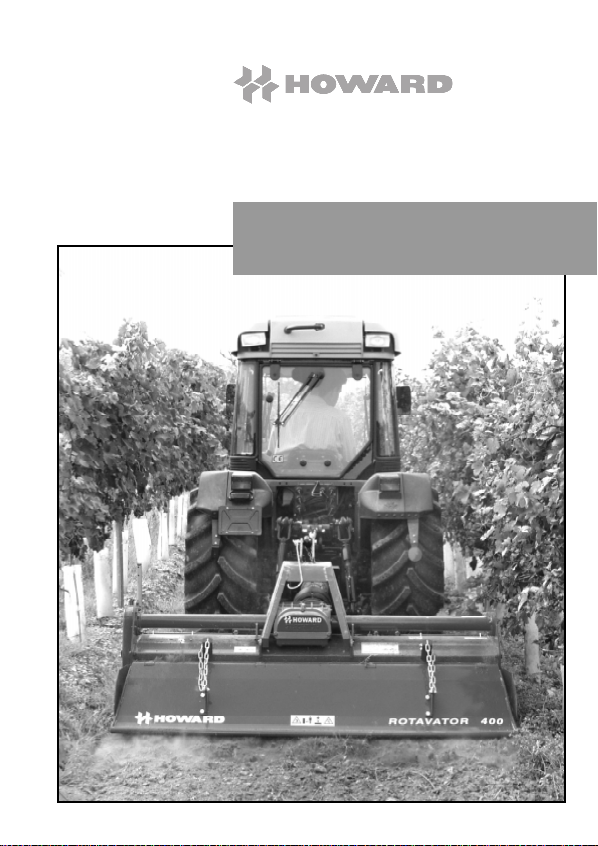
Rotavator 400
16
AT ALL TIMES
• Use the Rotavator only for the purpose for which it has
been designed, and in accordance with the instructions
in this operators manual.
• Ensure that only responsible, properly instructed people
operate this machinery. Inexperienced operators will
require training, followed initially by careful supervision.
• Children are not permitted to operate this machinery.
• Keep children well clear and appropriately supervised
when connecting/disconnecting the tractor, operating or
maintaining this machinery.
• Donotwearclothesthatare loose fitting or with drawstring
ties which can catch in moving parts.
• Wear appropriate protective clothing and equipment.
Boots are a minimum, however if your tractor is not fitted
with a controlled environment cab you may also need
protection from prolonged exposure either to noise, dust
or sunlight.
• Interpret ‘Left’ and ‘Right’ as if seated in the operators
seat and facing forward.
BEFORE OPERATION
• Read and understand this manual.
• The tractor to be connected to the Rotavator:
- Must be the tractor that the Rotavator has been
commissioned to operate with. Check that it has been
correctly maintained and has not been re-configured
(for example front weights removed etc) which may
reduce stability and control.
- Consult the Tractor Manufacturers Manual for
instructionson mounting implements andsafe working
methods.
- Isrecommendedto be fitted with a RollOverProtection
System (ROPS).
- Must be one the operator is familiar with.
• Priorto starting the tractor ensurethePTOisdisengaged
and the tractor is in neutral.
• Do not allow anyone to stand between the tractor and
Rotavator while backing the tractor up to attach it.
- Quick hitch systems are recommended for both Safety
and convenience.
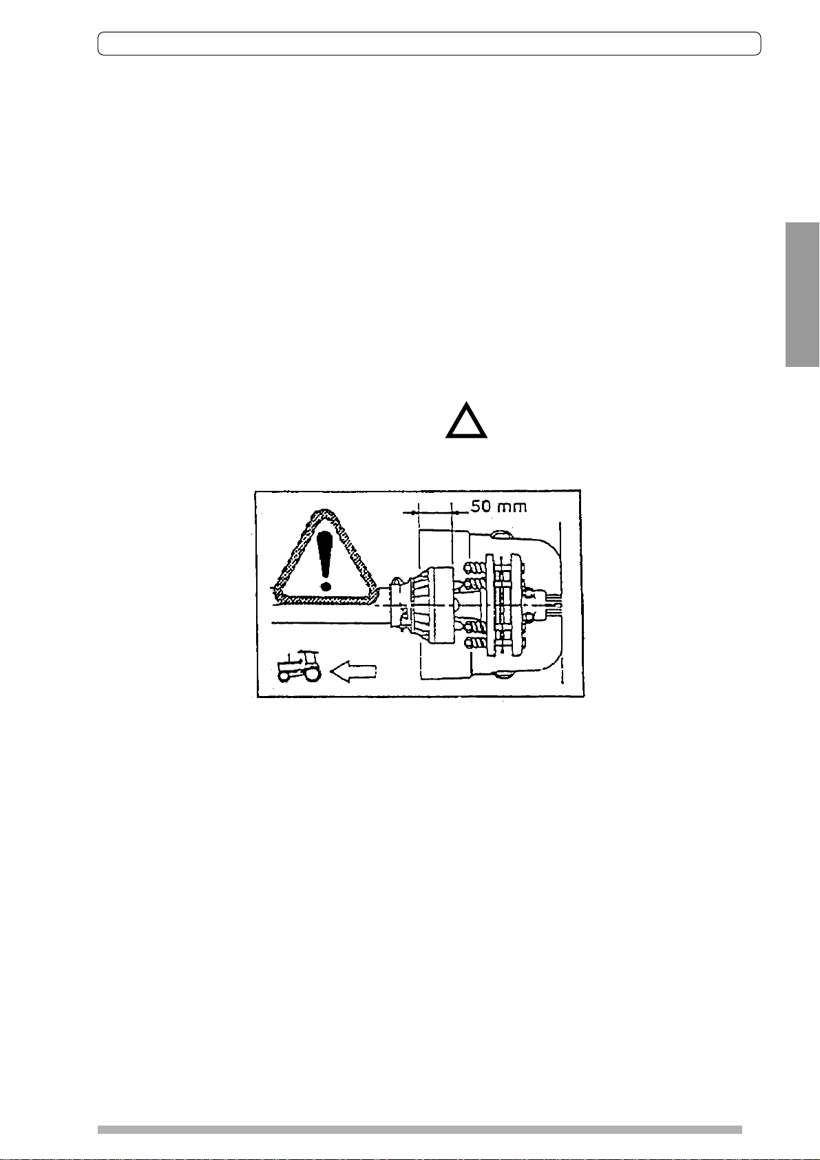
- Before attempting to connect the universal drive shaft
to the tractor, lower the Rotavator to the ground, stop
the tractor, apply the park brake and remove the key.
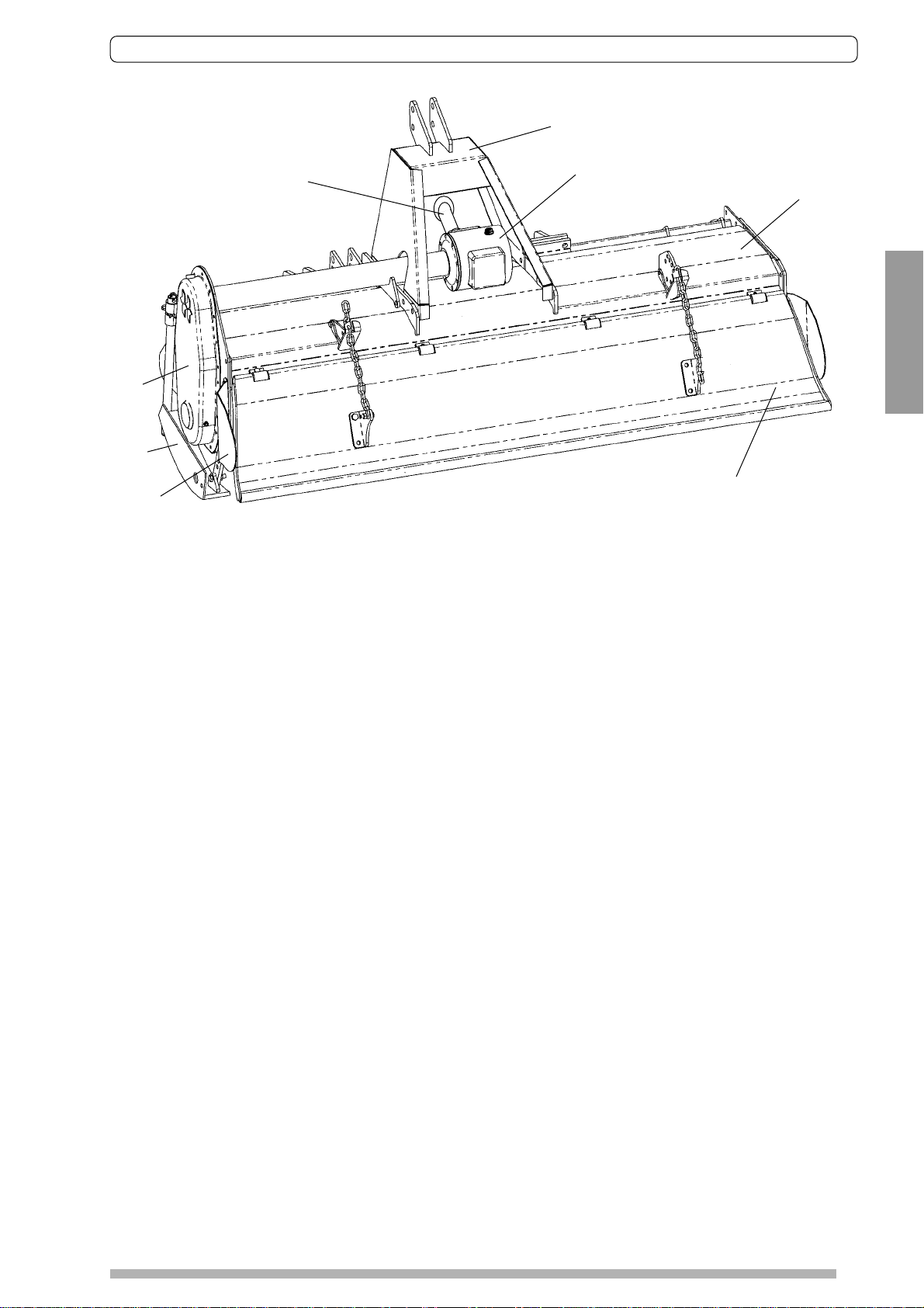
• Visually inspect the Rotavator and check:
- Hitch pins and drive shaft are secure.
- No components are excessively worn, cracked or
otherwise defective and all bolts are tight.
- Guards, covers, warning labels and safety devices are
all correctly fitted and operative.
- Maintenance as per schedule has been carried out.
- No tools or other unsecured items have been left on
the Rotavator.
• Practice operation of the tractor and Rotavator
combination.
- Take sufficient time to become completely familiar with
all controls, particularly those required to bring both
tractor and Rotavator to an emergency stop if so
required.
- Progressslowlyinitiallyandcheckstability,steeringand
braking are satisfactory.
• Ensure the work area is clear, especially of children or
animals.
• Inspect the work area for hidden obstructions which may
constitute a hazard.
DURING OPERATION
• Ensure the work area is clear, especially of children or
animals.
• Do not attempt to start the tractor or engage the PTO
until correctly seated in the driver’s seat.
• Never leave the tractor running unattended.
• Do not allow passengers on the Rotavator. [Or on the
tractor unless approved seating is available.]
• Never attempt to make adjustments or perform
maintenance functions while the Rotavator is operating.
• Observe all safe driving procedures:
- Reduce speed when working on sloping ground or
during sharp turns.
- Donotattempttoworkonsteeplyslopinggroundwhere
there is a risk of the tractor overturning.
- Do not attempt to work near the edge of drop-offs or
banks.
- Avoid sudden starts and stops.
• After striking an obstacle, stop the tractor and implement
and inspect it for damage. Repair as necessary before
continuing.
• Disengage the PTO when transporting the implement or
when not in use.
• When halting operation, even temporarily, lower the
Rotavator to the ground, stop the tractor, apply the park
brake and remove the key.
• Allow the Rotavator sufficient time to cool down before
performing any maintenance, or changing gears in the
Selectaspeed gearbox. [Oil and other transmission
components may be hot enough to inflict burns.]
• Note:
- By virtue of its mode of operation it is not possible to
totally enclose a Rotavator with guards.
- Contact with the blades while operating can result in
severe injury or death.
- Do not allow anybody (operators, maintenance
personnel,bystandersorespeciallychildren)anywhere
nearthebladeswhilsttheimplement is operating. Note
that children will often be attracted to placing objects
into the blades if you leave it running - this machine is
not a toy.
- Be aware that Rotavator blades will not only cut, but
drag limbs etc. into further danger.
- Ensure thatall shielding is in place before operating. If
guardsareremovedformaintenancework,ensurethey
are replaced correctly upon completion. Repair or
replace any damaged guards.
- NEVER place hands or feet under the Rotavator, nor
endeavour to make any repairs or adjustments while
the blades are rotating; they are capable of inflicting
serious injury.
- NEVERtouchthebladesorattempttofreeanyjammed
obstacle while the tractor engine is running.The clutch
may be slipping and removal of any obstruction may
allow the blades to rotate, the result possibly being
serious injury.