HP PCIe U320 User manual

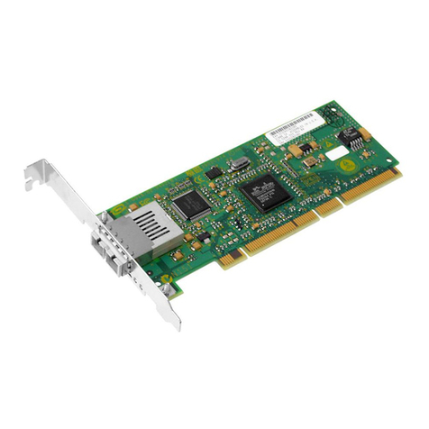
HP StorageWorks U320e SCSI Host Bus
Adapter
User guide
AH627-96001
Part number: AH627–96001
1st edition: March 2007

Legal and notice information
© Copyright 2007 Hewlett-Packard Development Company, L.P.
Confidential computer software. Valid license from HP required for possession, use or copying. Consistent with FAR 12.211 and
12.212, Commercial Computer Software, Computer Software Documentation, and Technical Data for Commercial Items are licensed
to the U.S. Government under vendor's standard commercial license.
The information contained herein is subject to change without notice. The only warranties for HP products and services are set forth
in the express warranty statements accompanying such products and services. Nothing herein should be construed as constituting
an additional warranty. HP shall not be liable for technical or editorial errors or omissions contained herein.
Microsoft, Windows, Windows XP, and Windows NT are U.S. registered trademarks of Microsoft Corporation.
Adobe and Acrobat are trademarks of Adobe Systems Incorporated.
UNIX is a registered trademark of The Open Group.
ATTO is a trademark of ATTO Technology, Inc.

Contents
Aboutthisguide .......................... 7
Intendedaudience...................................... 7
Documentconventionsandsymbols .............................. 7
HPtechnicalsupport..................................... 8
Customerselfrepair ..................................... 8
Productwarranties...................................... 8
Subscriptionservice ..................................... 8
HPwebsites......................................... 8
Documentationfeedback ................................... 9
1Features............................. 11
Summary of specifications .................................. 11
2Installation............................ 13
Systemrequirements .................................... 13
Installationoverview .................................... 13
Planningtheinstallation................................... 14
Preparingtheserver .................................... 16
Installingtheadapterhardware ............................... 17
Connectingthedevices................................... 17
Installingdrivers...................................... 18
Windows....................................... 18
Linux......................................... 18
Updating firmware..................................... 19
ValidatingtheSCSIbus(Windowsonly)............................ 19
3SCSIDomainValidationutility(Windowsonly) ........... 21
InstallingtheDomainValidationutility ............................ 21
RunningtheDomainValidationutility............................. 22
4Configurationtool........................ 25
Installing the ATTO ConfigurationTool ............................ 25
Using the ConfigurationTool ................................ 26
Navigating the ATTO ConfigurationTool ......................... 26
NVRAMsettings...................................... 27
5Troubleshooting.......................... 31
Investigatingtheadapterinstallation ............................. 31
InvestigatingtheSCSIcablesanddevices........................... 31
Windowsinstallationtroubleshooting............................. 32
Linuxinstallationtroubleshooting............................... 35
ConfigurationToolmessages ................................ 36
MaximizingperformanceinWindows ............................ 37
Usethelatestdriver .................................. 37
Setregistryforlargeblocktransfers............................ 37
Increasetransfersize.................................. 38
AnalyzeyourI/Os................................... 38
User guide 3

6 Technical specifications ..................... 39
ARegulatorycomplianceandsafety.................. 41
Regulatorycompliance................................... 41
Regulatory compliance identificationnumbers ....................... 41
Regulatorycompliancelabellocation......................... 41
FederalCommunicationsCommissionnotice........................ 41
ClassAequipment................................. 41
ClassBequipment................................. 42
Declaration of conformity for products marked with the FCC logo, United States only . . . . . 42
Modifications................................... 42
Cables...................................... 42
Laserdevice ..................................... 42
Lasersafetywarning................................ 43
Internationalnoticesandstatements ............................. 43
Canadiannotice(avisCanadien) ............................ 43
ClassAequipment................................. 43
ClassBequipment................................. 43
EuropeanUnionregulatorynotice ............................ 43
BSMInotice...................................... 43
Japanesenotice.................................... 44
Koreannotices .................................... 44
Safety .......................................... 44
Taiwanbatteryrecyclingnotice ............................. 44
Powercords...................................... 44
Japanesepowercordnotice............................... 45
Wasteelectricalandelectronicequipmentdirective....................... 45
Czechoslovakiannotice................................. 45
Danishnotice..................................... 45
Dutchnotice ..................................... 46
Englishnotice..................................... 46
Estoniannotice .................................... 46
Finnishnotice..................................... 47
Frenchnotice ..................................... 47
Germannotice .................................... 47
Greeknotice ..................................... 48
Hungariannotice ................................... 48
Italiannotice ..................................... 49
Latviannotice..................................... 49
Lihuaniannotice.................................... 50
Polishnotice ..................................... 50
Portuguesenotice ................................... 51
Slovakiannotice.................................... 51
Sloveniannotice.................................... 51
Spanishnotice .................................... 52
Swedishnotice .................................... 52
B Electrostatic discharge ...................... 53
Preventingelectrostaticdamage ............................... 53
Groundingmethods .................................... 53
Glossary............................. 55
Index .............................. 59
4
Figures
1..Kitcontents .................................. 13
2..Removingthebracketscrews........................... 15
3..Removing the stand-offs ............................. 16
4..Card with low-profilebracket........................... 16
5..ConnectingtheSCSIcableandterminator..................... 17
6..DomainValidationUtility ............................ 22
7..ATTOTechnologyBanner ............................ 32
8..Adapter in Windows Device Manager . . . . . . . . . . . . . . . . . . . . . . . 32
User guide 5

Tables
1..Documentconventions............................... 7
2..SCSIcapabilities................................ 14
3..Tabs displayedbydevicetype .......................... 26
4..Windowsinstallationtroubleshootingtable..................... 32
5..Linuxtroubleshootingtable............................ 35
6..MessagesfromNVRAMtabactions. ....................... 36
7..Messages fromFlashtabactions ......................... 37
6

About this guide
This guide provides information about:
•installing and connecting devices to the HP StorageWorks U320e SCSI Host Bus Adapter
•configuring the HP StorageWorks U320e SCSI Host Bus Adapter
•troubleshooting the HP StorageWorks U320e SCSI Host Bus Adapter
Intended audience
This guide is intended for the person who installs, administers, and troubleshoots servers and storage
systems. HP assumes you are qualified in servicing computer equipment and trained in recognizing
hazards in products with hazardous energy levels.
Document conventions and symbols
Table 1 Document conventions
Convention Element
Blue text: Table 1 Cross-reference links and e-mail addresses
Blue, underlined text: http://www.hp.com Website addresses
Bold text •Keys that are pressed
•Text typed into a GUI element, such as a box
•GUI elements that are clicked or selected, such as
menu and list items, buttons, tabs, and check boxes
Italic text Text emphasis
Monospace text •File and directory names
•System output
•Code
•Commands, their arguments, and argument values
Monospace, italic text •Code variables
•Command variables
Monospace, bold text Emphasized monospace text
WARNING!
Indicates that failure to follow directions could result in bodily harm or death.
CAUTION:
Indicates that failure to follow directions could result in damage to equipment or data.
IMPORTANT:
Provides clarifying information or specific instructions.
User guide 7

NOTE:
Provides additional information.
TIP:
Provides helpful hints and shortcuts.
HP technical support
For worldwide technical support information, see the HP support website:
http://www.hp.com/support
Before contacting HP, collect the following information:
•Product model names and numbers
•Technical support registration number (if applicable)
•Product serial numbers
•Error messages
•Operating system type and revision level
•Detailed questions
Customer self repair
This product was designed for customer self repair. Under this product's warranty, if a part needs
replacing, HP ships the part directly to you so that you can install it at your convenience.
For more information about CSR, contact your local service provider. For North America, see the CSR
website:
http://www.hp.com/go/selfrepair
Product warranties
For information about HP StorageWorks product warranties, see the warranty information website:
http://www.hp.com/go/storagewarranty
Subscription service
HP recommends that you register your product at the Subscriber's Choice for Business website:
http://www.hp.com/go/e-updates
After registering, you will receive e-mail notification of product enhancements, new driver versions,
firmware updates, and other product resources.
HP websites
For additional information, see the following HP websites:
•h
ttp://www.hp.com
•http://www.hp.com/go/storage
•http://www.hp.com/service_locator
•http://www.hp.com/support/manuals
8About this guide

•http://www.hp.com/support/downloads
Documentation feedback
HP welcomes your feedback.
To make comments and suggestions about product documentation, please send a message to
storagedocs.feedback@hp.com. All submissions become the property of HP.
User guide 9

10 About this guide

1 Features
The HP StorageWorks U320e SCSI Host Bus Adapter represents the seventh generation of parallel SCSI
technology, an I/O interface that is committed to increased performance while maintaining backward
compatibility and legacy support. The HP StorageWorks U320e SCSI Host Bus Adapter is a dual channel
Ultra 320 SCSI PCIExpress (PCIe) host adapter.
Summary of specifications
Feature Details
Card type Low-profile PCI express
Slot connector PCIe x4
Devices supported HP StorageWorks MSL Tape Libraries, 1/8 G2 Tape Autoloader
Device modes supported LVD and SE
Number of peripherals that can
be connected
15 per channel (see Table 2,page14)
Number of SCSI busses 2
SCSI modes supported Ultra320, Ultra160, Ultra2
SCSI data transfer rate Up to 320 MB/s per channel
LUN support 0–7 LUNs by default
For more information about the adapter features, specifications, and compatibility, see the "Technical
specifications" on page 39.
User guide 11

12 Features

2 Installation
CAUTION:
Back up your system data before changing or installing hardware.
Follow the steps in this chapter to install the host bus adapter.
11312
Figure 1 Kit contents
The HP StorageWorks U320e SCSI Host Bus Adapter package includes:
•Host bus adapter
•Half-height bracket
•CD containing documentation, drivers, and utilities
•Getting started poster and warranty card
System requirements
To install and use the HP StorageWorks U320e SCSI Host Bus Adapter you will need:
•A computer with an available x4 PCI Express expansion slot or larger, such as x8 or x16.
•The HP StorageWorks U320e SCSI Host Bus Adapter package.
CAUTION:
The host bus adapter contains components that are sensitive to electrostatic discharge (ESD). The host bus
adapter can be damaged by electrostatic discharge. Keep parts in electrostatic containers until needed.
Ensure that you are properly grounded when touching static-sensitive components.
Installation overview
WARNING!
To reduce the risk of personal injury or damage to the equipment, consult the safety information and user
documentation provided with the server before attempting the installation.
Many servers are capable of providing energy levels that are considered hazardous and are intended
to be serviced only by qualified personnel who have been trained to deal with these hazards. Do not
remove enclosures or attempt to bypass any interlocks that may be provided for the purpose of removing
these hazardous conditions.
User guide 13

WARNING!
When installing the adapter in a server in a rack, to reduce the risk of personal injury or damage to the
equipment, adequately stabilize the rack before extending a component outside the rack. Extend only
one component at a time. A rack may become unstable if more than one component is extended.
The installation procedure involves the following steps:
1. Planning the installation (see page 14)
2. Preparing the server (see page 16)
3. Installing the adapter hardware (see page 17)
4. Connecting the devices (see page 17)
5. Validating the SCSI bus (see page 19)
Planning the installation
To minimize system downtime, plan the installation before powering off the server:
1. Plan the SCSI busses.
The adapter has two channels. When planning your SCSI busses, keep the following in mind:
• Total bus cable length varies by the type of attached devices. See Table 2 for details on maximum
cable length. See the documentation for your devices to find the cable length inside the device.
Table 2 SCSI capabilities
Max.buslengthinmeters
SCSI standard Bus speed
MB/sec. max.
Bus width bits
Single-ended LVD
Max. device
support1
SCSI-1 586
—8
Fast SCSI 10 8 3 —8
Fast Wide SCSI 20 16 3 —16
Wide Ultra/WIDE
SCSI
40 16 1.5 —8
Wide Ultra/WIDE
SCSI
40 16 3 —4
Ultra2 SCSI 80 16 —12 16
Ultra160 SCSI 160 16 —12 16
Ultra320 SCSI 320 16 —12 16
1Including the HBA.
• Ifyoucombinewide16-bitandnarrow8-bitdevicesonthesameSCSIbus,connectthewide
devices first (closest to the connector).
• Refer to the documentation for your SCSI devices to determine whether they are Ultra2, Ultra160,
or Ultra320 SCSI.
NOTE:
HP recommends not mixing Single-Ended and LVD devices on the same bus because the host adapter
card will operate with Single-Ended signaling at UltraSCSI speeds, which will significantly decrease the
speedofhigh-performancetapedrives.
2. Plan the SCSI device termination.
14 Installation

The last device in the bus — that farthest from the adapter — must be properly terminated for each
SCSI bus. When planning device termination, keep the following in mind:
• Use an LVD terminator if you are only using LVD devices.
Although you can use a Single-Ended terminator, all devices will be limited to Ultra SCSI speeds and
cable lengths. Single-Ended devices require a Single-Ended terminator. If you use an LVD terminator
with Single-Ended devices, the system may hang or devices may not be seen on the SCSI bus. Some
termination manufacturers provide automatically sensing terminators.
• LVD Ultra2 and Ultra160 SCSI devices cannot supply their own termination.
• Wide (16-bit) and narrow (8-bit) devices can be connected together on the same connector of the
host adapter card, but wide devices must be attached first, followed by narrow devices.
To terminate the SCSI bus, the cable or adapter used to convert from a wide (68-pin) connector to
a narrow (50-pin) connector provides partial termination, allowing the upper 8-bits (or byte) of the
wide SCSI bus to be properly terminated. A narrow terminator should be used on the last narrow
device to terminate the rest of the SCSI bus. A SCSI bus without partial termination between the
wide and narrow devices may at first appear to work correctly, but occasional I/O errors occur
without proper termination.
• Termination power: Host adapters supply termination power to the bus at all times and many
SCSI devices are also able to supply termination power. SCSI signal quality, particularly with long
or marginal quality cables, may be improved if the device supplies the termination power. See
your device documentation for information on your device's ability to supply termination power.
3. Review system documentation to select an appropriate slot to install the adapter.
The combined power consumption of the expansion slots must not exceed the limits for your system.
If you have more than one expansion card installed, ensure power consumption is within the limits
outlined for your system.
4. If the selected installation slot is low profile, replace the mounting bracket on the adapter.
a. Remove the two screws on top of the board that secure the bracket to the board, as shown in
Figure 2.
11314
Figure 2 Removing the bracket screws
User guide 15

b. Use a small, flat screwdriver to remove the four stand-offs on the external connectors, as
shown in Figure 3.
11315
Figure 3 Removing the stand-offs
c. Remove the bracket and replace it with the low-profile bracket. Verify that the new bracket
is oriented correctly, as shown in Figure 4.
11316
Figure 4 Card with low-profile bracket
d. Replace the four stand-offs to secure the bracket to the board.
e. Attach the two screws to the high-profile bracket in case you need the larger bracket to install
the adapter in another server.
Preparing the server
To prepare the server for the new adapter:
1. Back up all data.
2. Perform anormalsystemshutdown.
3. Power down the server.
4. Power down all peripheral devices that are connected to the server.
5. Unplug the server’s AC power cords from the power outlet and then from the server.
6. Disconnect all peripheral devices from the server.
16 Installation

Installing the adapter hardware
CAUTION:
Electrostatic discharge can damage electronic components. Be sure you are properly grounded before
beginning this procedure. For more information, see "Appendix: Electrostatic discharge"onpage53.
To install the host bus adapter hardware:
1. Open the server case.
WARNING!
Toreducetheriskofpersonalinjuryfromhotsurfaces,allowthedrivesandtheinternal
system components to cool before touching them.
2. Install the adapter in the selected PCIe expansion slot. Consult your computer's documentation if you
have questions about how to install an expansion card in your system.
3. Close the computer case.
Connecting the devices
To connect the devices:
1. Connect SCSI devices with SCSI cables.
Insert a SCSI cable into a connector on the HP U320e SCSI Host Bus Adapter, as shown in Figure 5.
Verify that the connector is properly seated and tighten the screws on the connector. Connect the
other end of the cable to the firstdeviceinthebus. Connecttherestofthedevicestoeachother,if
applicable. Repeat to connect the devices to the second bus, if applicable.
11318
2 3
1
Figure 5 Connecting the SCSI cable and terminator
1. SCSI cable connection on the adapter
2. SCSI cable connection on the device
3. SCSI terminator
2. Connect a terminator to each device at the end of a SCSI bus.
3. Reconnect the power cables.
User guide 17

4. Poweruptheserverandperipherals.
The HP U320e SCSI Host Bus Adapter comes pre-configured to operate properly in a variety of common
setups. However, some systems may benefit by tuning the adapter for a specific application. See Chapter
4on page 25 for information on changing host adapter settings.
Installing drivers
After installing the HP StorageWorks U320e SCSI Host Bus Adapter, you must configure your system to
recognize and use it by installing drivers for your operating system.
NOTE:
IfyoualreadyhaveoneormoreHPStorageWorksU320eSCSIHostBusAdaptersinstalledintheserver
and you are installing additional adapters, you do not need to install drivers unless you are updating
apreviouslyinstalleddriver.
Windows
To install the Windows driver from the product CD:
1. Load the product CD into the computer. The CD will display an HTML page.
2. Click the arrow next to Drivers in the Extras section.
3. Double-click the driver package for your operating system to extract the files.
4. Navigate to the location where you extracted the files.
5. Double-click setup.exe.
6. Click Install.
To install the Windows driver from the HP website:
1. Download the driver package for your operating system from http://www.hp.com/support/u320e.
The driver package is a self-extracting archive.
2. In Windows Explorer, navigate to the location of the downloaded driver package. Double-click the
driver package to extract the files.
3. Navigate to the location where you extracted the files.
4. Double-click setup.exe.
5. Click Install.
Linux
To install the Linux driver package from the product CD:
1. Load the product CD into the computer. The CD will display an HTML page.
2. Click the arrow next to Drivers in the Extras section.
3. Copy the Linux driver package to the file system.
4. Unzip the driver package and view the readme.txt file for release notes and installation
instructions.
HP provides patches for the AH627A driver in the Linux 2.4 and 2.6 kernels to allow the driver to
operate on the HP StorageWorks U320e SCSI Host Bus Adapter.
To install the Linux driver package from the HP website:
1. Download the Linux driver package from http://www.hp.com/support/u320e.
18 Installation

2. Unzip the driver package and view the readme.txt file for release notes and installation
instructions.
HP provides patches for the AH627A driver in the Linux 2.4 and 2.6 kernels to allow the driver to
operate on the HP StorageWorks U320e SCSI Host Bus Adapter.
Updating firmware
The HP StorageWorks U320e SCSI Host Bus Adapter ships with the latest firmware installed. If you are
installing a new adapter, you do not need to update the firmware. If you are upgrading a previously
installed driver, update the adapter firmware to ensure proper operation.
Visit http://www.hp.com/support/u320e for the latest drivers and firmware.
To update the firmware, also called flash, using the ATTO Configuration tool:
1. Install the Configuration Tool on your system. (See Installing the ATTO Configuration Tool, page 25.)
2. Download the flash bundle from http://www.hp.com/support/u320e and extract the firmware
files to your desktop.
3. Launch the Configuration Tool.
4. In the Device window, select the ATTO Express PCI UL5D adapter.
5. In the Flash window, click Browse to find the flash bundle that you previously downloaded to your
desktop.
6. Click Update to update the flash ROM in the adapter.
7. Reboot your system for the flash changes to take effect.
Validating the SCSI bus (Windows only)
On Windows, install and run the SCSI Domain Validation utility to verify the connections in the SCSI
busses. See "SCSI Domain Validation utility (Windows only)" on page 21 for more information.
User guide 19

20 Installation
This manual suits for next models
1
Table of contents
Other HP Adapter manuals

HP
HP Bt500 User manual

HP
HP 561T User manual

HP
HP Dual Output USB Graphics Adapter User manual

HP
HP HP 3005PR User manual

HP
HP 41802A Quick start guide

HP
HP StoreFabric CN1100R User manual

HP
HP Photosmart 7100 User manual

HP
HP 665249-B21 User manual

HP
HP 11869A User manual

HP
HP 4X - DDR InfiniBand Mezzanine HCA Instruction sheet