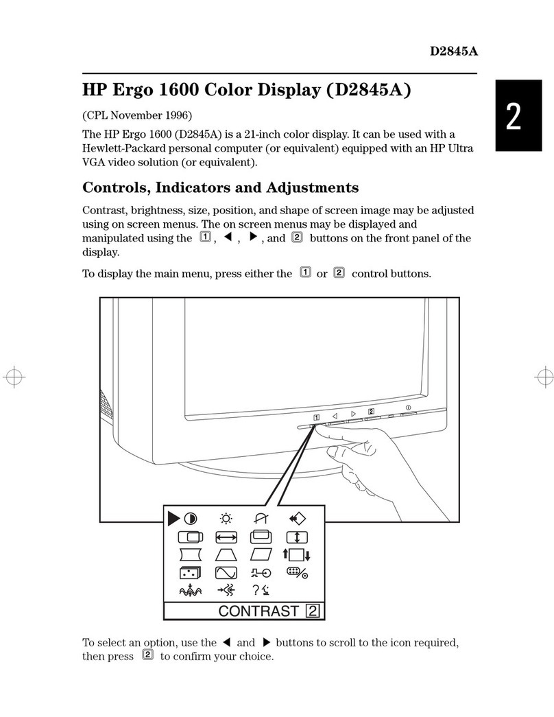
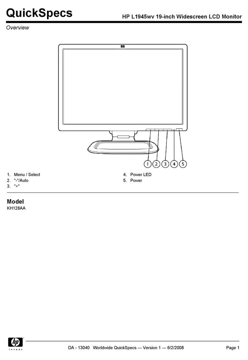
HP Presario CQ1569 User manual

15.6" LCD Color Monitor HP CQ1569
1
Service
Service
Service
HorizontalFrequency
24-83kHz
TABLE OF CONTENTS
Description Page Description Page
SAFETY NOTICE
ANY PERSON ATTEMPTING TO SERVICE THIS CHASSIS MUST FAMILIARIZE HIMSELF WITH THE CHASSIS
AND BE AWARE OF THE NECESSARY SAFETY PRECAUTIONS TO BE USED WHEN SERVICING ELECTRONIC
EQUIPMENT CONTAINING HIGH VOLTAGES.
CAUTION: USE A SEPARATE ISOLATION TRANSFOMER FOR THIS UNIT WHEN SERVICING
Table Of Contents.......……..............................…........1
Revision List.…........................................……......2
1. Monitor Specification..............................………........3
2. LCD Monitor Description…………………………….......4
3. Operation Instruction…………...............……...........5
3.1. General Instructions...........................…...........5
3.2. Control Button…………….…..............……...............5
3.3 Adjusting the Picture...........................…............6
4. Input/Output Specification............……………............9
4.1. Input Signal Connector............………….................9
4.2. Factory Preset Display Modes......…..................10
5. Panel Specification.....………………..................11
5.1. General Feature…….....………………..................11
5.2. Optical Characteristics………………………………11
6. Block Diagram……...................…………................12
6.1 Software Flow Chart………………………………...12
6.2.Electrical Block Diagram……………..….......14
7. Schematic……………......................................16
7.1 Main Board....……….......................................16
7.2 Power Board.….……....................................20
7.3 Key Board…………………………………………..23
7.4 Audio Board………………………………… …… .. 24
8.PCB Layout..…….................................. ........ ..... ...24
8.1. Main Board………........................................25
8.2. Power Board….......................................26
8.3. Key Board………............….......................28
9. Maintainability……….......................................29
9.1. Equipments and Tools Requirement..............29
9.2. Trouble Shooting……….............................30
9.2.1 Main Board…………..............................30
9.2.2 Power Board………..............................32
9.2.3 Key Board…………..............................34
10 White-Balance, Luminance adjustment...35
11.Mechanical Instructions……………..…...….......37
12. Monitor Exploded View………………..…....….......41
13. BOM List………………………………..……………42
14. Different Parts List.........…………..........................53
15.6" LCD Color Monitor HP CQ1569
2
Revision List
Version Date Revision History TPV Model Name
T6RGM5NMY5CPANE
T6RGM5NMY5CPACE
T6RGM5NMY5CQANE
T6RGM5NMY5CQACE
T6RGM5NKY5CPANE
T6RGM5NKY5CPACE
T6RGM5NDY5CPANE
T6RGM5NDY5CPACE
T6RGM5NQY5CQANE
T6RGM5NQY5CQACE
T6RGM5NLY5CPANE
T6RGM5NLY5CPACE
T6RGM5NQY5CPANE
T6RGM5NQY5CPACE
T6RGM5NQY5CMANE
T6RGM5NQY5CMACE
T6RGM5NTY5CPANE
T6RGM5NTY5CPACE
T6RGM5NCY5CPANE
A00 Feb.-17-2009 Initial release
T6RGM5NCY5CPACE

15.6" LCD Color Monitor HP CQ1569
3
1. Monitor Specification

15.6" LCD Color Monitor HP CQ1569
4
2. LCD Monitor Description
The LCD Monitor will contain main board, power board, a key board which house the flat panel control logic, brightness
control logic and DDC.
The power board will provide AC to DC Inverter voltage to drive the backlight of panel and the main board chips each
voltage.
Video signal, DDC
Power Board
(
Include ada
p
ter board
)
Flat Panel and
CCFL backlight
Main Board RS232 Connector
For white balance
adjustment in
factory mode
HOST Computer
CCFT Drive.
AC-IN
110V-240V
Monitor Block Diagram
Keyboard

15.6" LCD Color Monitor HP CQ1569
5
3. Operation Instructions
3.1 General Instructions
The monitor settings can be adjusted from the On-Screen Display (OSD) menu. To access the OSD
and adjust screen settings base on your viewing preference, do the following:
1. If the monitor is not already on, press the power button to turn on the monitor. The power indicator
will light up.
2. To access the OSD menu, press the Menu button.
3. To navigate through the Main Menu, press the – or + buttons. Once the desired function is
highlighted, press the Menu button to activate the Submenu. Press the Menu button to select the
highlighted function.
4. Press the – or + button to change the settings of the selected function. Press the – or + button to
select another function in the Submenu.
5. Press Auto/OK to select the highlighted function.
3.2 Control Button

15.6" LCD Color Monitor HP CQ1569
6
3.3 Adjust the Picture

15.6" LCD Color Monitor HP CQ1569
7

15.6" LCD Color Monitor HP CQ1569
8

15.6" LCD Color Monitor HP CQ1569
9
4. Input/Output Specification
4.1 Input Signal Connector
4.1.1 D-SUB connector
Pin Signal Pin Signal
1 Red Video 9 +5V Supply
2 Green Video 10 Logic Ground
3 Blue Video 11 NC
4 NC 12 DDC-Serial Data
5 DDC-Return 13 H-Sync.
6 Red Ground 14 V-Sync.
7 Green Ground 15 DDC-Serial Clock

15.6" LCD Color Monitor HP CQ1569
10
8 Blue Ground
VGA connector layout
PIN 1 PIN 5
PIN 11
4.2 Factory Preset Display Modes

15.6" LCD Color Monitor HP CQ1569
11
5. Panel Specification
5.1 General Feature
5.2 Optical Characteristics

15.6" LCD Color Monitor HP CQ1569
12
6. Block diagram
6. 1 Software Flow Chart
1
2
N
Y
5
Y
N
10
Y
N
12
Y
N
7
Y
N
6
4
3
8
9
14
11
13
Y
N
15
Y
N
16
17
19
Y
N
18

15.6" LCD Color Monitor HP CQ1569
13
REMARK:
1) MCU initialize.
2) Is the EEprom blank?
3) Program the EEprom by default values.
4) Get the PWM value of brightness from EEprom.
5) Is the power key pressed?
6) Clear all global flags.
7) Are the AUTO and SELECT keys pressed?
8) Enter factory mode.
9) Save the power key status into EEprom.
Turn on the LED and set it to green color.
Scalar initialize.
10) In standby mode?
11) Update the lifetime of back light.
12) Check the analog port, are they’re any signals coming?
13) Does the scalar send out an interrupt request?
14) Wake up the scalar.
15) Are there any signals coming from analog port?
16) Display "No connection Check Signal Cable" message. And go into standby mode after the message
disappear.
17) Program the scalar to be able to show the coming mode.
18) Process the OSD display.
19) Read the keyboard. Is the power key pressed?

15.6" LCD Color Monitor HP CQ1569
14
6.2 Electrical Block Diagram
6.2.1 Scalar Board
Scalar HUM56AWL-LF
(Include ADC、OSD、MCU)
(U401)
FLASH MEMORY
PM25LV010A (U402)
D-Sub Connector
(CN101)
EPR_SDA
EPR SCL
Panel Interface
(CN405)
EEPROM
M24C02
(U405)
H sync
V sync
RGB
EEPROM
M24C04
(U402)
DB15_SDA,
DB15 SCL

15.6" LCD Color Monitor HP CQ1569
15
6.2.2 Inverter / Power Board
CN902
DIM
EMI filter Bridge
Rectifier
and Filter
Start Circuit
PWM
Control IC
Transformer Rectifier
diodes
AC input
12V
ON/OFF
Control
PWM
Control IC
Feedback
Circuit
LC
Resonance
Transformer MOSFET
Over
Voltage
Lamp
ON/OFF
Feedback
Circuit
Over
Voltage
Protect
5V

15.6" LCD Color Monitor HP CQ1569
16
7. Schematic
7.1 Main Board
DSUB_5V
TSUM16FR SCHEMATIC
PA[0..1]
CMVCC1
CMVCC1
XGA/SXGA
VCC1.8
R15.6 A
OTS R-series A
37Friday , October 24, 2008
715Gxxxx-A <
称爹
>
01.Top
Gxxxx-A-X-X-1-081021
OEM MODEL Size
Rev
Date Sheet of
TPV MODEL
PCB NAME
称爹
T P V ( Top Victory Electronics Co . , Ltd. )
Key Component
絬
隔
瓜
絪
腹
VCC3.3
VCC1.8
PB[0..9]
PANEL_VCC1
PA[4..9]
LVDS OUTPUT
PANEL_VCC1
CMVCC1
VCC3.3
DSUB_5V
02.Input
DSUB_R+
DSUB_G+
DSUB_B+
DSUB_V
DSUB_R-
DSUB_G-
DSUB_B-
DET_CABLE
DSUB_H
DSUB_SOG
DDC1_SDA
DDC1_SCL
DSUB_5V
VCC3.3
CMVCC1
03.Scalar
DSUB_R+
DSUB_G+
DSUB_SOG
DSUB_B+
DSUB_R-
DSUB_G-
DSUB_B-
DSUB_H
DSUB_V
Adj_BACKLIGHT
VCC1.8
VCC3.3
PA[0..1]
PB[0..9]
DDC1_SDA
DDC1_SCL
DET_CABLE
on_BACKLIGHT
PPWR_ON#
PANEL_ID#
Volume#
Mut e
CMVCC
PA[4..9]
CMVCC1
VCTRL
CMVCC
05.Power
on_BACKLIGHT
Adj_BACKLIGHT
VCC1.8
CMVCC
VCC3.3
Mute
Volume#
PANEL_ID#
DSUB_5V
CMVCC1 VCTRL
PANEL_VCC1
CMVCC
VCC3.3
04.Output
PANEL_VCC1
PB[0..9]
PA[0..1]
PPWR_ON#
PA[4..9]

15.6" LCD Color Monitor HP CQ1569
17
C106
NC /0.047uF
C434
0.22uF16V
DSUB_V 5
NC
NC
CMVCC1
2N3904S-RTK/PS
C111
5pF/50V
V_Sy nc
VGA_G-
C104
5pF/50V
NC
VGA_G+
DSUB_SDA
C110
0.047uF
Q407
2N3904S-RTK/PS
R476
H_Sy nc DSUB_H 5
DGND
DDC1_SCL
D403
BAV70
3
1
2
C103
22pF
DDC1_SDA
VGA_B+
DDC1_SDA
DSUB_5V
R118
10K 1/16W 5%
GND POW ER
R114
100R 1/16W 5%
R106
2K2 1/16W 5%
R15.6 A
OTS R-series B
47Wednes day , October 29, 2008
715G3244-E <
称爹
>
02.Input
Gxx xx-A-X-X-1-081021
OEM MODEL Size
Rev
Date Sheet of
TPV MODEL
PCB NAME
称爹
T P V ( Top Victory Electronics Co . , Ltd. )
Key Component
絬
隔
瓜
絪
腹
ZD104
RLZ5.6B
R116
75R 1/16W 5%
VGA_B+
100R 1/16W 5%
R105
2K2 1/16W 5%
R113
100R 1/16W 5%
C108
5pF/50V
U405
R472
EDID external
VCC 3.3 5,7
10K 1/16W 5%
VGA_R+
R112
75R 1/16W 5%
VGA_B-
C107
0.047uF
4K7 1/16W 5%
DSUB_R+ 5
4K7 1/16W 5%
DSUB_5V 7
VGA_PLUG
H_Sy nc
R473
4K7 1/16W 5%
DSUB_B- 5
R120
10K 1/16W 5%
ZD 103
RLZ5.6B
NC
NC
R103 100R 1/ 16W 5%
DET_CABLE 5
NC
VGA_B+
DSUB_SCL
NC
VGA_R-
VGA_B-
R475 47R 1/16W 5%
VGA_G-
R476 47R 1/16W 5%
0.22uF
R474
R111
100R 1/16W 5%
VGA_R+
CN101
DB15
1
6
2
7
3
8
4
9
5
11
12
13
14
15
10
17 16
DSUB_SCL
VGA_PLUG
NC
R113
DSUB_G- 5
C113
0.047uF
V_Sy nc
U405
M24C02-WMN6TP
1
2
3
45
6
7
8A0
A1
A2
VSSSDA
SCL
WP
VCC
R121
10K 1/16W 5%
EDID internal
10K 1/16W 5%
4K7 1/16W 5%
VGA_G+
CMVCC1
VGA_R-
DDC1_SCL
FB101
BEAD
1 2
U102
AZC199-04S
1
2
3 4
5
6
I/O1
GND
I/O2 I/O3
VDD
I/O4
DSUB_SCL
R101 0R 05 1/10W 5%
DSUB_5V
R104
100R 1/16W 5%
DSUB_5V
NC
DSUB_SDA
NC
D403
DSUB_SDA
C101
0.047uF
FB103
BEAD
1 2
NC
DSUB_SOG 5
47R 1/16W 5%
R121
C102
22pF
DDC1_SDA5
NC
M24C02-WMN6TP
R110
R475
R473
R117
100R 1/16W 5%
R102 100R 1/ 16W 5%
C105
0.047uF
VGA_G+
FB102
BEAD
1 2
R108
100R 1/16W 5%
NC
C109
0.047uF
DSUB_R- 5
R107
75R 1/16W 5%
DSUB_G+ 5
VGA_R+
R472
4K7 1/16W 5%
DDC1_SCL5
Q407
100R 1/16W 5%
U103
AZC199-04S
1
2
3 4
5
6
I/O1
GND
I/O2 I/O3
VDD
I/O4
CMVCC1 5,7
BAV70
R110
100R 1/16W 5%
C434
R474
4K7 1/16W 5%
47R 1/16W 5%
VCC 3.3
R115
100R 1/16W 5%
DSUB_B+ 5
R120
R109
NC /390 OHM 1/16W

15.6" LCD Color Monitor HP CQ1569
18
C418
NC
R456 0R05 1/16W
DSUB_R-4
NC NC or 100R 1/16W 5%
R419 100R 1/16W 5%
R452 100R 1/16W 5%
Max condition for LED:
1. Vcc = 3.3 V
2. Current = 12 mA
FW need to be modified.
VCC3.3
PB[0..9] 6
VCC1.87
VCC1.8
PB5
DDC1_SCL4
KEY 2
R454
KEY2
R457 0R05 1/16W
POWER_KEY#
R418 100R 1/16W 5%
R405 100R 1/16W 5%
R417
10K 1/16W 5%
R462 NC
LVDS
LED_O
R403 390 OHM 1/16W
NC
PB9
TOUCH POWER
VCC3.34,7
R459
47K 1/16W 5%
C411 22pF
LED_GRN/BLUE
R413 100R 1/16W 5%
ZD404
NC/UDZSNP5.6B
1 2
PANEL_ID# 7
R414 120R 1/16W 5%
CMVCC14,7
PANEL_ID# and POWER_KEY#
could be optional.
Q401
AO3401
CMVCC
CMVCC1
MSC L
LED_G/ B
NC
R425, C418 depend on
case.
PB3
AVDD
VCC3.3
TOUCH POWER
+
C410
10uF/50V
C417
0.1uF/ 16V
R469
10K 1/16W 5%
According to MST's
request, reserve another
RST circuit.
CN406
NC/CONN
1
2
3
4
5
6
7
8
ZD402
NC/UDZSNP5.6B
1 2
U403
VCC1.8
DSUB_B-4
PB0
CN408
CONN
1
2
3
4
5
6
10K 1/16W 5%
X4 0 1
14.31818MHz
1 2
adj_BACKLIGHT 7
R458
10K 1/16W 5%
M24C04-WMN6TP
CMVCC1
NC
DSUB_R+4
PPWR_ON# 6
LED_OR ANGE
LED_ORANGE
C433
NC
R408
10K 1/16W 5%
FB401
300OHM
R425
NC
R404
10K 1/16W 5%
R467
120R 1/10W 5%
C406
0.1uF /16V
R454
10K 1/16W 5%
R460
NC
Q403
2N3906S-RTK/PS
0.22uF16V
PB1
EE_WP
Near to Connect
10K 1/16W 5%
WP
C408
0.22uF 16V
For NVRAM
PB8
Mut e 7
VCC3.3
R461 NC
VCTRL 7
CN402
NC/CONN
1
2
3
4
5
6
Without NVRAM
NC or 100R 1/16W 5%
MSC L
R426 NC
C412 22pF
R453
10K 1/16W 5%
C404
0.1uF /16V
C415
0.1uF/ 16V
DSUB_V4
Volume# 7
PB2
R451 100R 1/16W 5%
CMVCC1
NC
R421
NC
DSUB_H4
100R 1/16W 5%
DDC1_SDA4
NC
R424
U403
M24C04-WMN 6TP
1
2
3
45
6
7
8NC
E1
E2
VSSSDA
SCL
WC
VCC
POWER _KEY #
CMVCC
PB6
R466
10K 1/16W 5%
NC
R15.6 A
OTS R-series C
715G3244-E <
称爹
>
03.Scalar
Gxxx x-A-X-X-1-081021
OEM MO DEL Size
Rev
TPV MODEL
PCB N AME
称爹
T P V ( Top Victory Electronics Co . , Ltd. )
Key Component
絬
隔
瓜
絪
腹
U402
PM25LV010A
1
2
3
4
8
7
6
5
CE#
SO
WP#
GND
VDD
HOLD#
SCK
SI
C416
0.1uF/ 16V
100R 1/16W 5%
Q402
2N3906S-RTK/PS
C401
0.1uF/ 16V
DSUB_G+4
NC
R412 100R 1/16W 5%
KEY 1
R407
10K 1/16W 5%
R478 100R 1/16W 5%
R411 100R 1/16W 5%
R427
3.9K OH M 1/16W
+
C430
NC/10uF/50V
100R 1/16W 5%
DSUB_B+4
R428
3.9K OH M 1/16W
VCC3.3
MSD A
R464 NC
C429
0.22uF16V
ZD403
NC/UDZSNP5.6B
1 2
CMVCC7
10K 1/16W 5%
AVDD
R406
6K8 1/16W 5%
R420
VCC3.3
C409
0.1uF /16V
For RSTN detect
function
LED_GRN/BLUE
R420 NC
DSUB_G-4
DET_CABLE 4
NC
EE_WP
MSD A
R455
10K 1/16W 5%
R455
PB[0..9]
ZD401
NC/UDZSNP5.6B
1 2
C413
0.1uF/ 16V
CN407
NC/CONN
1
2
3
4
5
6
7
NC
VCC3.3
PB7
R463 NC
DSUB_SOG4
R451
FB404
NC
CN409
NC/CONN
1
2
3
4
5
6
7
R426
AVDD
R402
0R05 1/16W
R401
0R05 1/16W
R468 470R 1/ 16W 5%
R471 470R 1/ 16W 5%
C403
0.1uF /16V
CMVCC7
R452
CMVCC1
LED_O
LED_G/B
TSUM1PFR-LF
U401
13
10
11
8
12
9
7
16
17
4
15
14
21
23
22
24
27
56
1
2
35
36
37
38
39
40
41
42
43
44
45
46
47
48
49
50
34
33
5
6
32
31
52
30
18
19
62
20
28
55
58
59
60
61
63
64
25
26
54
51
53
29
57
3
RIN0P
GIN 0P
SOGIN0
BIN0P
RIN0M
GIN 0M
BIN0M
HSYNC0
VSYNC0
REXT
REFP
REFM
SDO
SCK
SCZ
SDI
PWM2/GPIO_P24
PWM1/GPIO_P25
XI N
XO U T
LVA2P
LVA2M
LVA1P
LVA1M
LVA0P
LVA0M
LVB3P
LVB3M
LVBCKP
LVBCKM
LVB2P
LVB2M
LVB1P
LVB1M
LVB0P
LVB0M
LVA3M
LVA3P
GND
AVDD_ADC
MOD E [ 1]
MOD E [ 0]
VCTRL
VDDC
DDCA_SDA/RS232_TX
DDCA_SCL/rs232_RX
PWM0/GPIO_P26
GPIO_P15/PWM0
GPIO_P27/PWM1
GPIO_P12
GPIO_P00/ SAR1
GPIO_P01/ SAR2
GPIO_P06
GPIO_P07
GPIO_P13
GPIO_P14
GPIO_P11/I2C _MDA
GPIO_P10/I2C _MCL
RST
VDDP
VDDC
GND
RSTN
GND
R424 100R 1/16W 5%
R453
When NVRAM is used,
POWER_KEY# and PANEL_ID#
will not be used at same
time.
KEY1
R410 120R 1/16W 5%
on_BACKLIGHT 7
C407
0.1uF /16V
R409
10K 1/16W 5%
C429
PB4
C414
0.1uF/ 16V
R470
120R 1/10W 5%

15.6" LCD Color Monitor HP CQ1569
19
2006-11-7 Add pull up 4K7 to MVCC
PB7
PB4
R435
4K7 1/16W 5%
FB402
120OHM
PPWR_ON#
PB3
PB4
PB0
Q411
NC/AO4411
1
2
3
4
8
7
6
5
S
S
S
G
D
D
D
D
PB9
R434
150R 1/4W 5%
G
PANEL_VCC1 7
PB5
PB[0..9]5
PB9
CN405
CONN
2
4
6
8
10
12
14
1
3
5
7
9
11
13
PANEL_VCC
PB[0..9] PB6
Q405
AO3401G
D
S
PB1
PB7
R433
10K 1/16W 5%
PB3
PB8
PANEL_VCC
PPWR_ON#5
PANEL_VCC1
PB2
AO3401L
Q404
PMBS3906
PB5
PB2
PB8
S
R15.6 A
OTS R-series A
715Gxxxx A
04 Output
Gxxxx-A-X-X-1-081021
OEM MOD EL Size
Rev
TPV MOD EL
PCB NAME
T P V ( Top Victory Electronics Co . , Ltd. )
Key Component
絬
隔
瓜
絪
腹
R477
150R 1/4W 5%
PB0
R436
100K 1/16W 5%
1
+
C421
100UF16V
C420
0.1uF/16V
2
3
PB1
PB6
C419
0.1uF/16V
D

15.6" LCD Color Monitor HP CQ1569
20
VCC3.3 4,5
Q406
2N3904S-RTK/PS
VCC3.3
VCC3.3
CMVCC
D401
BAT54C
3
1
2
OTHER
CN404
CONN
1
2
3
4
5
6
7
8
9
CMVCC1
R450 NC
NC(R0402)
2008/01/14
BAT99 : If 0.05A,VF=1.0V
BAV70 : If 0.05A,VF=1.0V
It's need to use Low Dropout Regulator.
NC
on_BACKLIGHT 5
R441
1K 1/16W 5%
R446
NC
VCC3.3
Volume
R440
4K7 1/16W 5%
C422
0.1uF/16V
VCC3.3
Mut e 5
Volume# 5
U404 can use package 223 or 252.
D402
SM340A
+
C435
100UF16V
VCC3.3
Q410
KN2907AS
NC
C432
0.1uF/16V
R448
4K7 1/16W 5%
D403
R442
100R 1/16W 5%
CMVCC
FB403 NC
adj_BACKLIGHT 5
VCC3.3
CMVCC1
LG
VCC1.8
U406
AP1117D33L-13
1
2
3
ADJ(GND)
VOUT
VIN
FB405 NC
VCTRL5
VCC3.3
BKLT-VBRI
DSUB_5V
U404
AP1117D33L-13
1
2
3
ADJ (GND)
VOUT
VIN
C428
0.1uF/16V
CMVCC1 4,5
CMVCC5
D401
PANEL_VCC1
+
C426
100UF16V
Q409
KN2907AS
PANEL_VCC1 6
Due to LG doen't request PC'99 Function.
BKLT-EN
R437
10K 1/16W 5%
C436
0.1uF/16V
DSUB_5V 4
R15.6
A
OTS R-series
77Friday , October 24, 2008
715Gxxxx-A <
称
05.Power
Gxxxx-A-X-X-1-081021
OEM MODEL Size
Rev
Date Sheet of
TPV MODEL
PCB NAME
称爹
T P V ( Top Victory Electronics Co . , Ltd. )
Key Component
絬
隔
瓜
絪
腹
+
C423
100UF16V
PANEL_ID# 5
CMVCC5
BAT54C
BKLT-EN
MVC C
VCC1.8 5
CMVCC1
C_PANEL_INDEX
CMVCC
Mut e
R465
NC
R447
10K 1/16W 5%
BAV99
+
C427
100UF16V
C425
NC
BKLT-VBRI Q408
2N3904S-RTK/PS
R439
10K 1/16W 5%
CMVCC
Volume
R449
NC
Table of contents
Other HP Monitor manuals

HP
HP Pavilion FX75 User manual

HP
HP EliteDisplay E273m Manual

HP
HP V244a Assembly instructions

HP
HP HC270cr Installation instructions

HP
HP NK571AA User manual

HP
HP L1506 User manual

HP
HP LD 220 User manual

HP
HP 24WM User manual

HP
HP LP2065 - 20.1" LCD Monitor User manual

HP
HP EliteDisplay Webcam Backlit LCD Monitor User manual