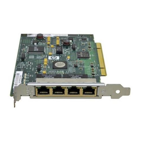
HP Edgeline EL1000 User manual

HPE Edgeline EL1000 System User
Guide
Part Number: 868773-002
Published: May 2017
Edition: 2
Abstract
This document is for the person who installs, administers, and troubleshoots servers and
storage systems. Hewlett Packard Enterprise assumes you are qualified in the servicing of
computer equipment and trained in recognizing hazards in products with hazardous energy
levels.

© 2017, 2017 Hewlett Packard Enterprise Development LP
Notices
The information contained herein is subject to change without notice. The only warranties for Hewlett
Packard Enterprise products and services are set forth in the express warranty statements accompanying
such products and services. Nothing herein should be construed as constituting an additional warranty.
Hewlett Packard Enterprise shall not be liable for technical or editorial errors or omissions contained
herein.
Confidential computer software. Valid license from Hewlett Packard Enterprise required for possession,
use, or copying. Consistent with FAR 12.211 and 12.212, Commercial Computer Software, Computer
Software Documentation, and Technical Data for Commercial Items are licensed to the U.S. Government
under vendor's standard commercial license.
Links to third-party websites take you outside the Hewlett Packard Enterprise website. Hewlett Packard
Enterprise has no control over and is not responsible for information outside the Hewlett Packard
Enterprise website.
Acknowledgments
Intel®, Itanium®, Pentium®, Intel Inside®, and the Intel Inside logo are trademarks of Intel Corporation in
the United States and other countries.
Microsoft® and Windows® are either registered trademarks or trademarks of Microsoft Corporation in the
United States and/or other countries.
Linux™is the registered trademark of Linus Torvalds in the U.S. and other countries.
SD™ and microSD™are trademarks or registered trademarks of SD-3C in the United States, other
countries or both.
NVIDIA™is a trademark of NVIDIA Corporation in the U.S. and other countries.

Contents
Component identification.......................................................................6
PCIe configuration........................................................................................................................ 6
Front panel components.................................................................................................... 6
Front panel LEDs and buttons........................................................................................... 6
Right side components.......................................................................................................7
System board components................................................................................................ 8
PXI/PXIe configuration..................................................................................................................8
Front panel components.................................................................................................... 8
Front panel LEDs and buttons........................................................................................... 9
Right side components.....................................................................................................10
System board components.............................................................................................. 10
DIP switch..............................................................................................................11
Hot-plug drive LED definitions.....................................................................................................11
Operations............................................................................................. 13
Install an AC power supply......................................................................................................... 13
Install the DC power supply........................................................................................................ 13
Power down the system..............................................................................................................17
Power up the system.................................................................................................................. 18
Mount the system........................................................................................................................18
Dismount the system...................................................................................................................18
Dismounting the system from a wall mount..................................................................... 18
Dismounting the system from a rack mount.....................................................................19
Dismounting the system from an ETSI rack mount..........................................................19
Dismounting the system from an Enterprise rack mount................................................. 19
Remove the access panel...........................................................................................................19
Installing the fans........................................................................................................................ 20
Installing the cartridge.................................................................................................................20
Install the mini-PCIe adapter board............................................................................................ 21
Setup...................................................................................................... 22
Optional services.........................................................................................................................22
Optimum environment.................................................................................................................22
Temperature requirements............................................................................................... 22
Power requirements......................................................................................................... 22
Installing hardware options ........................................................................................................ 23
Registering the product...............................................................................................................23
Hardware options installation..............................................................24
Installing the wall mounting option kit......................................................................................... 24
Installing the rack mounting option kit.........................................................................................24
Installing the ETSI rack mounting option kit................................................................................25
Installing the Enterprise rack mounting option kit....................................................................... 26
Installing the drive....................................................................................................................... 28
Installing the card options........................................................................................................... 28
Install the PCIe card.........................................................................................................28
Contents 3

Install the PXI/PXIe card ............................................................................................... 30
Installing the mini-PCIe module options......................................................................................31
Install a half-length mini-PCIe module option...................................................................31
Installing a full-length mini-PCIe module..........................................................................32
Configuration.........................................................................................33
Accessing the System Utilities menu.......................................................................................... 33
Viewing or updating the DHCP address using the serial console cable..................................... 34
Finding the IP address through DHCP........................................................................................34
Setting the static IP address using the serial console cable....................................................... 35
Software and configuration utilities.................................................... 37
Product QuickSpecs................................................................................................................... 37
Supported operating systems and drivers matrix .......................................................................37
HPE iLO...................................................................................................................................... 37
Active Health System....................................................................................................... 37
Active Health System data collection.................................................................... 38
Active Health System log.......................................................................................38
iLO RESTful API support..................................................................................................38
Integrated Management Log............................................................................................ 39
HPE Edgeline Component Pack................................................................................................. 39
HP Smart Update Manager..............................................................................................39
UEFI System Utilities.................................................................................................................. 39
Using UEFI System Utilities............................................................................................. 40
Flexible boot control......................................................................................................... 40
Restoring and customizing configuration settings............................................................41
Secure Boot configuration................................................................................................41
Embedded UEFI shell...................................................................................................... 41
Embedded Diagnostics option......................................................................................... 41
iLO RESTful API support for UEFI................................................................................... 42
Re-entering the server serial number and product ID...................................................... 42
Troubleshooting.................................................................................... 43
HPE Edgeline Troubleshooting Guide........................................................................................ 43
Battery....................................................................................................44
Battery specifications.................................................................................................................. 44
Replace the system battery........................................................................................................ 44
Warranty and regulatory information.................................................. 46
Warranty information...................................................................................................................46
Regulatory information................................................................................................................46
Safety and regulatory compliance....................................................................................46
Belarus Kazakhstan Russia marking............................................................................... 46
Turkey RoHS material content declaration.......................................................................47
Ukraine RoHS material content declaration..................................................................... 47
Electrostatic discharge.........................................................................48
Preventing electrostatic discharge.............................................................................................. 48
Grounding methods to prevent electrostatic discharge...............................................................48
4Contents
Specifications........................................................................................49
Product QuickSpecs................................................................................................................... 49
Environmental specifications ..................................................................................................... 49
Environmental specifications-system components support matrix...................................51
Mechanical specifications........................................................................................................... 51
Power supply specifications........................................................................................................51
PXI/PXIe specifications...............................................................................................................53
Electrical load regulation specifications........................................................................... 53
Chassis cooling specifications......................................................................................... 53
Pollution specifications.....................................................................................................53
Shock and vibration specifications................................................................................... 53
Acoustic emission specifications .....................................................................................53
HPE EMC compliance testing.......................................................................................... 55
System synchronization clock specifications................................................................... 55
Support and other resources...............................................................57
Websites..................................................................................................................................... 57
Accessing Hewlett Packard Enterprise Support......................................................................... 57
Information to collect........................................................................................................ 57
Accessing updates......................................................................................................................58
Customer self repair....................................................................................................................58
Remote support.......................................................................................................................... 58
Acronyms and abbreviations...............................................................60
Documentation feedback..................................................................... 61
Contents 5

Component identification
PCIe configuration
Front panel components
654
3
21
Item Description
1 iLO port
2 Network port 11
3 Network port 21
4 USB 3.0 ports
5 Drives
6 Cartridge
1Network connections are available in 1G and 10G. The 1G is shown.
Front panel LEDs and buttons
Item Description Status
1 iLO and network port link
LED • Green = Linked to network
• Off = No network connection
2 iLO and network port activity
LED • Flashing green = Network activity
• Off = No network activity
Table Continued
6 Component identification

Item Description Status
3 Cartridge UID LED/button • Blue = Cartridge ID is selected
• Flashing Blue = Cartridge firmware update is in
progress or iLO IRC is in use
• Off = Cartridge ID is not selected
4 Cartridge health LED • Green = Normal operation
• Flashing Amber = Degraded condition
• Flashing Red = Critical condition
• Off = No power
5 Cartridge power LED • Green = Normal operation
• Flashing green = iLO booting
• Amber = Standby operation
• Off= No power
Right side components
1
2 3 4
Item Description
1 Antenna connectors
2 PCIe slot 1
3 PCIe slot 2
4 Power supply
Right side components 7

System board components
Item Description
1 Fan 1
2 Fan 2
3 Fan 3
4 Power distribution board
5 System battery
PXI/PXIe configuration
Front panel components
21
1 6 7 82 3 4 5
Item Description
1 iLO port
2 Network port 11
3 Network port 21
Table Continued
8 System board components

Item Description
4 USB 3.0 ports (4)
5 Drives (2)
6 Cartridge
7 PXI/PXIe slot 3
8 PXI/PXIe slot 2
1Network connections are available in 1G and 10G. The 1G is shown.
Front panel LEDs and buttons
21
543
1 2
Item Description Status
1 iLO and network port link
LED • Green = Linked to network
• Off = No network connection
2 iLO and network port activity
LED • Flashing green = Network activity
• Off = No network activity
3 Cartridge UID LED/button • Blue = Cartridge ID is selected
• Flashing Blue = Cartridge firmware update is in
progress or iLO IRC is in use
• Off = Cartridge ID is not selected
4 Cartridge health LED • Green = Normal operation
• Flashing Amber = Degraded condition
• Flashing Red = Critical condition
• Off = No power
5 Cartridge power LED • Green = Normal operation
• Flashing green = iLO booting
• Amber = Standby operation
• Off= No power
Front panel LEDs and buttons 9

Right side components
1 32 4 5 6 7 8
Item Description
1 Antenna connector
2 Antenna connector
3 Antenna connector
4 Antenna connector
5 REF in connector
6 REF out connector
7 Antenna connector
8 Power supply
System board components
1
2
3
5 64
Item Description
1 Fan 1
2 Fan 2
Table Continued
10 Right side components

Item Description
3 Fan 3
4 DIP Switch1
5 Power distribution board
6 System battery
1The fan cage might have to be removed to access the switch
DIP switch
Position Default Function
S1 Off • Off = Fan normal mode
• On = Fan high mode
Hot-plug drive LED definitions
When a drive is configured as part of a SmartArray and connected to a powered-up controller, the drive
LEDs indicate the condition of the drive. If no SmartArray adapter is present, then these drives will not be
hot pluggable, but will still show the activity LEDs.
Item LED Status Definition
1Locate Solid blue The drive is being identified by a host application.
Flashing
blue
The drive carrier firmware is being updated or requires an
update.
2Activity
ring
Rotating
green
Drive activity
Off No drive activity
3Do not
remove
Solid white Do not remove the drive. Removing the drive causes one or
more of the logical drives to fail.
Off Removing the drive does not cause a logical drive to fail.
Table Continued
DIP switch 11

4Drive
status
Solid green The drive is a member of one or more logical drives.
Flashing
green
The drive is rebuilding or performing a RAID migration, strip size
migration, capacity expansion, or logical drive extension, or is
erasing.
Flashing
amber/
green
The drive is a member of one or more logical drives and predicts
the drive will fail.
Flashing
amber
The drive is not configured and predicts the drive will fail.
Solid amber The drive has failed.
Off The drive is not configured by a RAID controller.
12 Component identification

Operations
This chapter describes the hardware operations carried out prior to and after installing or removing a
hardware option, or performing a server maintenance or troubleshooting procedure.
Before performing these hardware operations, review and observe the server warnings and cautions.
Install an AC power supply
Procedure
1. Align the power supply to the system.
2. Insert the power supply until it locks in place.
3. Connect the power cord and tie wrap the cable.
Install the DC power supply
Procedure
1. Remove the ring tongue from the top of the power supply.
2. Crimp the ring tongue to the ground cable from the -48V power source.
Operations 13

3. Remove the black connector from the rear of the power supply.
4. Loosen the screws on the connector.
14 Operations

5. Attach the (earthed) cable to the ground screw and washer and tighten to 13 lb-in of torque. The
ground cable must be connected before connecting the -48V wire and return wire.
6. Insert the -48V wire into the left side of the connector and tighten the screw to 10 lb-in of torque.
7. Insert the return wire into the right side of the connector and tighten the screw to 10 lb-in of torque.
Operations 15

8. Insert the power supply into the power supply bay until it clicks into place.
9. Insert the connector into the power supply.
16 Operations

10. Attach the cables to the power supply handle with the hook-and-loop strap.
11. Route the power cord. Use best practices when routing power cords and other cables. A cable
management arm is available to help with routing. To obtain a cable management arm, contact a
Hewlett Packard Enterprise authorized reseller.
12. Make sure the -48V DC power source is off or the PDU breaker is in the off position, and then
connect the power cord to the -48V DC power source or PDU.
13. Turn on the -48V power source or switch the PDU breaker to the on position to supply -48V to the
power supply.
14. Be sure that the green power supply LED is on.
Power down the system
About this task
Before powering down the system for any upgrade or maintenance procedures, back up critical system
data and programs.
Before performing chassis maintenance, shut down all cartridges installed in the system.
Power down the system 17

Procedure
• Use one of the following methods to power down the system:
◦ Press and release the Power On/Standby button of the cartridges installed in the system.
This method initiates a controlled shutdown of applications and the OS before the system enters
standby mode.
◦ Press and hold the Power On/Standby button of the cartridges installed in the system for more than
4 seconds to force the system to power down.
This method forces the system to power down without properly exiting applications and the OS. If
an application stops responding, you can use this method to force a shutdown.
Verify the system is in standby mode and the system power LED is off.
Power up the system
About this task
If the system is connected to a power source, it powers up automatically by default. Generally, it has to be
powered up only after a manual shutdown. However, using iLO, cartridges can be individually configured
to not power up automatically.
Procedure
• Use one of the following methods to power up the system:
◦ Press the Power On/Standby button of the cartridge installed in the system.
◦ Remotely power up the system through iLO.
Mount the system
The following kits are available to mount your system:
•Wall mounting kit
•Rack mounting kit
•ETSI rack mounting kit
•Enterprise rack mounting kit
Dismount the system
Dismount the system, based on the mount installed:
•Dismounting the system from a wall mount
•Dismounting the system from a rack mount
•Dismounting the system from an ETSI rack mount
•Dismounting the system from an Enterprise rack mount
Dismounting the system from a wall mount
About this task
To dismount the system from a wall mount, slide the EL1000 system off the wall-mounting screws.
It is not necessary to remove the wall mounting plate from the EL1000 system. Hewlett Packard
Enterprise recommends having a cart to place the system upon, which allows you to service the system
without removing the wall mounting plate or cables.
Should you need to service the system in another location, perform the following steps.
18 Power up the system

Procedure
1. Remove the four T-15 Torx screws securing the wall mounting plate to the bottom of the system.
2. Disconnect all cables.
Dismounting the system from a rack mount
Procedure
1. Loosen the 2 captive screws on the front of rack mount shelf.
2. Slide the EL1000 system and shelf out from the rack mounts to the front.
3. Unplug the power cable and disconnect all cables from the system.
4. Remove the system from the shelf assembly by lifting vertically.
Dismounting the system from an ETSI rack mount
Procedure
1. Loosen the 2 captive screws on the front of rack mount shelf.
2. Slide the EL1000 system and shelf out from the rack mounts to the front.
3. Unplug the power cable and disconnect all cables from the system.
4. Remove the system from the shelf assembly by lifting vertically.
Dismounting the system from an Enterprise rack mount
Procedure
1. Slide the system out of the rack.
2. Unplug the power cable and disconnect all cables from the system.
3. Remove the retention bracket from the Enterprise rack mount.
4. Lift and remove the system from the rack mount.
Remove the access panel
Procedure
• Using a Torx driver, remove the two T10 Torx screws securing the access panel to the system.
Dismounting the system from a rack mount 19

Installing the fans
Procedure
1. Align the fan with the fan slots of the system.
2. Squeeze the tabs on either side of the fan, and then slide it into the bay until it clicks in place.
Installing the cartridge
About this task
No cartridges supported on the system support Legacy BIOS Boot mode. For more information, see the
user and maintenance guide for your cartridge.
Procedure
• Align and install the cartridge into the system.
20 Installing the fans
Other manuals for Edgeline EL1000
1
Table of contents
Other HP PCI Card manuals
HP
HP Vectra VEi 7 User manual

HP
HP 673642-B21 User manual

HP
HP 4X - DDR InfiniBand Mezzanine HCA Instruction sheet

HP
HP A6826A How to use

HP
HP Vectra VL6 8 User manual

HP
HP NC570C User manual

HP
HP 435508-B21 User instructions

HP
HP StorageWorks fca2384 User manual

HP
HP Vectra VL6 6 User manual

HP
HP Xw460c - ProLiant - Blade Workstation User manual

HP
HP Vectra VEi 7 User manual

HP
HP Xw4600 - Workstation - 2 GB RAM User manual

HP
HP PCIe 2-Port 10GbE User manual

HP
HP Vectra VEC 7 User manual

HP
HP NC150T User manual

HP
HP VL600 - Vectra - 128 MB RAM User manual

HP
HP A7173A User manual

HP
HP Compaq Pro 6305 User manual

HP
HP Vectra VL410 User manual

HP
HP NC1020 User instructions