HP 70340A User manual

About this Manual
We’ve added this manual to the Agilent website in an effort to help you support
your product. This manual is the best copy we could find; it may be incomplete
or contain dated information. If we find a more recent copy in the future, we will
add it to the Agilent website.
Support for Your Product
Agilent no longer sells or supports this product. Our service centers may be able
to perform calibration if no repair parts are needed, but no other support from
Agilent is available. You will find any other available product information on the
Agilent Test & Measurement website, www.tm.agilent.com.
HP References in this Manual
This manual may contain references to HP or Hewlett-Packard. Please note that
Hewlett-Packard's former test and measurement, semiconductor products and
chemical analysis businesses are now part of Agilent Technologies. We have
made no changes to this manual copy. In other documentation, to reduce
potential confusion, the only change to product numbers and names has been in
the company name prefix: where a product number/name was HP XXXX the
current name/number is now Agilent XXXX. For example, model number
HP8648A is now model number Agilent 8648A.

Quick Start Guide
HP 70340A/70341A
Signal Generators
ABCDE
HP P
art No. 5960-7095
Printed in USA September 1992
Edition B.0.0

Notice
The information contained in this document is sub ject to change without notice.
Hewlett-Packard makes no warrantyof any kind with regard to this material, including,
but not limited to, the implied warranties of merchantability and tness for a particular
purpose. Hewlett-Packard shall not be liable for errors contained herein or for incidental or
consequential damages in connection with the furnishing, performance, or use of this material.
Restricted Rights Legend.
Use, duplication, or disclosure by the U.S. Government is sub ject to restrictions as set forth
in subparagraph (c) (1) (ii) of the Rights in Technical Data and Computer Software clause
at DFARS 252.227-7013 for DOD agencies, and subparagraphs (c) (1) and (c) (2) of the
Commercial Computer Software Restricted Rights clause at FAR 52.227-19 for other agencies.
c
Copyright Hewlett-Packard Company 1992
All Righ
ts Reserv
ed. Reproduction, adaptation, or translation without prior written
permission is prohibited, except as allow
ed under the cop
yrigh
tla
ws.
1400 F
oun
taingro
v
eP
arkw
a
y
,Santa Rosa, CA 95403-1799, USA

Certification
Hewlett-Packard Company certies that this pro duct met its published specications at the
time of shipment from the factory. Hewlett-Packard further certies that its calibration
measurements are traceable to the United States National Institute of Standards and
Technology, to the extent allowed by the Institute's calibration facility, and to the calibration
facilities of other International Standards Organization members.
Warranty
This Hewlett-Packard instrument pro duct is warranted against defects in material and
workmanship for a p erio d of one year from date of shipment. During the warranty perio d,
Hewlett-Packard Company will, at its option, either repair or replace pro ducts whichproveto
be defective.
For warranty service or repair, this pro duct must be returned to a service facility designated
b
yHewlett-P
ac
k
ard. Buy
er shall prepa
yshipping c
harges to Hewlett-P
ac
k
ard and
Hewlett-P
ac
kard shall pa
y shipping charges to return the pro duct to Buy
er. Ho
w
ev
er, Buy
er
shall pay all shipping c
harges, duties, and taxes for pro ducts returned to Hewlett-P
ac
k
ard
from another coun
try
.
Hewlett-P
ac
k
ard w
arran
ts that its soft
w
are and rm
w
are designated by Hewlett-Pac
k
ard for
use with an instrumen
twill execute its programming instructions when properly installed on
that instrumen
t. Hewlett-P
ac
kard do es not w
arran
tthat the operation of the instrumen
t, or
soft
w
are, or rm
w
are will beunin
terrupted or error-free.
Limita
tion of W
arranty
The foregoing w
arrant
yshall not apply to defects resulting from improp er or inadequate
main
tenance b
yBuy
er, Buy
er-supplied soft
w
are or in
terfacing, unauthorized mo dication or
misuse, operation outside of the en
vironmen
tal specications for the pro duct, or improp er
site preparation or maintenance.
NO OTHER WARRANTY IS EXPRESSED OR IMPLIED. HEWLETT-PACKARD
SPECIFICALLY DISCLAIMS THE IMPLIED WARRANTIES OF MERCHANTABILITY
AND FITNESS FOR A PARTICULAR PURPOSE.
Exclusive Remedies
THE REMEDIES PR
O
VIDED HEREIN ARE BUYER'S SOLE AND EX
CLUSIVE
REMEDIES. HEWLETT-P
A
CKARD SHALL NOT BE LIABLE F
OR ANY DIRECT,
INDIRECT, SPECIAL, INCIDENT
AL, OR CONSEQUENTIAL D
AMAGES, WHETHER
BASED ON CONTRA
CT, TOR
T, OR ANY OTHER LEGAL THEOR
Y.
Assistance
Pr
o
duct maintenanc
eagr
e
ements and other customer assistanc
eagr
e
ements ar
eavailable for
Hew lett-Packar
dpr
o
ducts.
F
or any assistanc
e, c
ontact your ne
ar
est Hew lett-Packar
dSales and Service Oc
e.
iii

Safety Symbols
The following safetysymbols are used throughout this manual. Familiarize yourself with each
of the symbols and its meaning before operating this instrument.
CAUTION
The
CAUTION
sign denotes a hazard. It calls attention to a procedure
which, if not correctly p erformed or adhered to, could result in damage to
or destruction of the pro duct or the user's work. Do not proceed b eyond a
CAUTION
sign until the indicated conditions are fully understoo d and met.
WARNING
The
WARNING
sign denotes a hazard. It calls attention to a procedure which,
if not correctly performed or adhered to, could result in injury to the user. Do
not proceed beyond a
WARNING
sign until the indicated conditions are fully
understood and met.
DANGER
The
DANGER
sign denotes an imminent hazard to people. It warns the reader
of a procedure which, if not correctly performed or adhered to, could result
in injury or loss of life. Do not proceed beyond a
D
ANGER
sign until the
indicated conditions are fully understood and met.
iv

General Safety Considerations
WARNING
The instructions in this document are for use by qualified personnel only.To
avoid electrical shock, do not perform any servicing unless you are qualified
to do so.
The opening of covers or removal of parts is likely to expose dangerous
voltages. Disconnect the instrument from all voltage sources while it is being
opened.
The power cord is connected to internal capacitors that may remain livefor
five seconds after disconnecting the plug from its power supply.
This is a Safety Class 1 Product (provided with a protective earthing ground
incorporated in the power cord). The mains plug shall only be inserted in a
socket outlet provided with a protective earth contact. Any interruption of the
protective conductor inside or outside of the instrument is likelytomakethe
instrument dangerous. Intentional interruption is prohibited.
For continued protection against fire hazard, replace fuse only with same
type and ratings, (type nA/nV). The use of other fuses or materials is
prohibited.
W
ARNING
Before this instrument is switched on, mak
esure it has been properly
grounded through the protectiv
econductor of the ac po
w
er cable to asock
et
outlet pro
vided with protectiv
eearth contact.
Any interruption of the protectiv
e(grounding) conductor, inside or outside
the instrument, or disconnection of the protectiv
e earth terminal can result in
personal injury
.
Before this instrument is switched on, mak
esure its primary po
w
er circuitry
has been adapted to the v
oltage of the ac po
wer source.
F
ailure to set the ac po
w
er input to the correct voltage could cause damage
to the instrument when the ac power cable is plugged in.
v

The Signal Generator at a Glance
The HP 70340A Synthesized Signal Generator
vi

1.
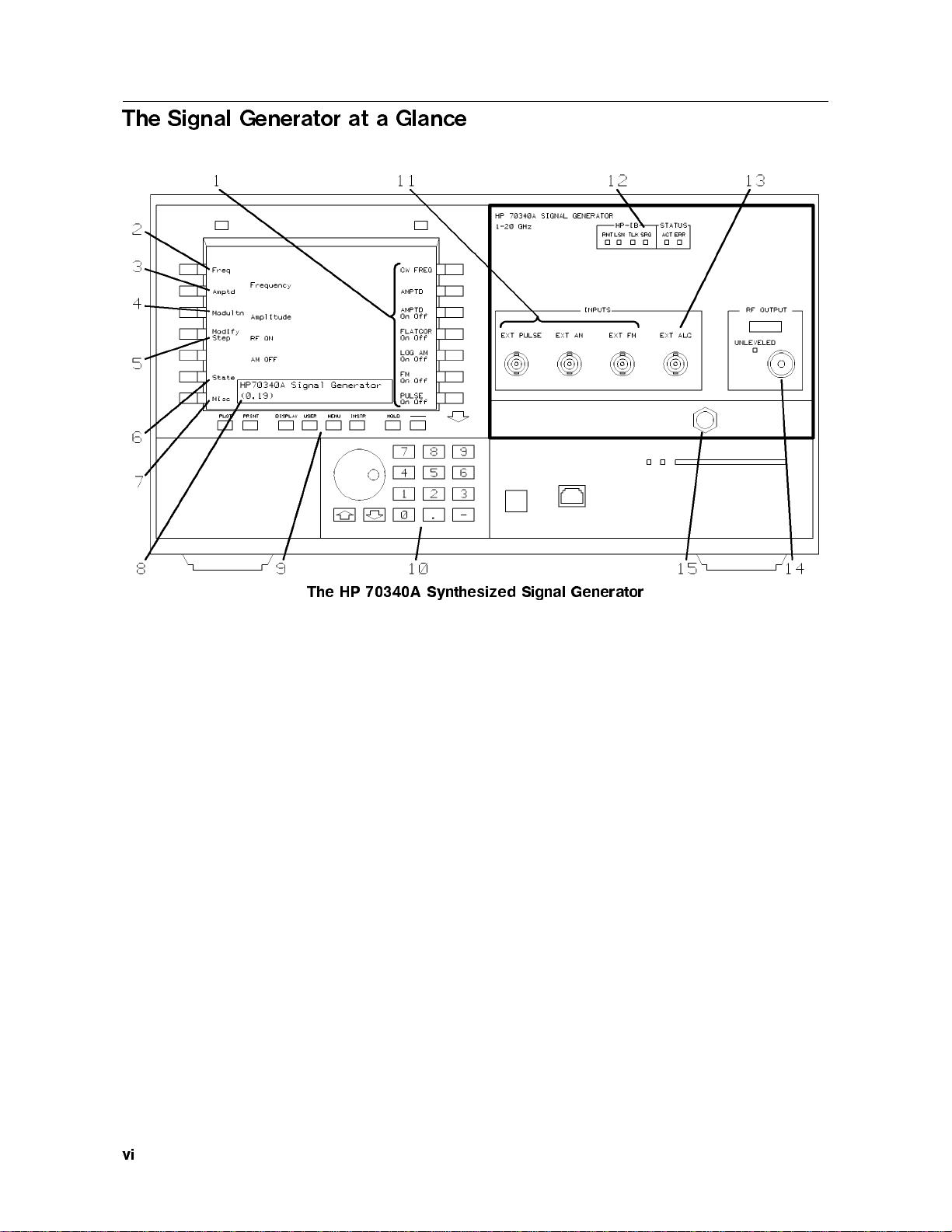
Softkeys turn signal
generator
functions
and menus
on and o and/or allow data
entry.
2.
The
Frequency menu
accesses the CW frequency and
the frequency multiplier value
of the RF output signal.
3.
The
Amplitude menu
accesses the output p ower level
functions and metho ds of RF
output signal leveling.
4.
The
Modulation menu
accesses mo dulation t
ype (FM,
Log AM, and pulse
mo dulation).
5.
The
Modify Step men
u
lets
y
ou c
hange the knob incremen
t
v
alue or the
4
*
54
+
5
k
eys step
size.
6.
The
State menu
saves/recalls most of the signal
generator's op erating
parameters to/from anyof nine
nonvolatile register lo cations.
7.
The
Miscellaneous menu
accesses signal generator
features (suchasservice
functions) which are less
frequently used.
8.
The
data entry b ox
indicates
the current active parameter, if
any, and its value.
9.
The
display keys
allo
wy
ou
to c
ho ose the instrumen
tfron
t
panel and access error
messages.
10.
The
data en
try k
eys
are
used to en
ter and mo dify
function parameters.
11.
The
mo dulation inputs
provide BNC connections for
external mo dulating signals.
12.
The
HP-IB and Status
LEDs
indicate the state of the
instrument: when it is in front
panel mo de or in HP-IB mo de,
and when an error message
exists.
13.
The
External Automatic
Level Control
connector is used
as the feedback path to the
signal generator when RF
output power is leveled
externally.
14.
The
RF OUTPUT
connector is the signal
generator's main RF output.
The UNLEVELED LED
indicates whether or not output
po
w
er is lev
eled.
15.
The Hex Nut
Latc
h
allo
ws
easy installation/remov
al of the
signal generator mo dule.
The fron
t panel pro cedures and examples in this book are v
alid whether or not the HP
70341A is installed in the Mo dular Measuremen
tSystem, MMS. F
or an illustration of the HP
70340A with the HP 70341A, refer to the
HP 70340A/41A User's Guide
.
In This Book
This book pro
vides a w
a
yfor y
ou to start using the HP 70340A signal generator (and HP
70341A frequency extension mo dule) quic
kly and pro ductively.Itgiv
es y
ou an o
verview of
some basic signal generator features while making y
ou a
ware of other more complex features.
\The Signal Generator at a Glance" sho
ws y
ou the various con
trols and features of the
signal generator and mainframe/display fron
t panel.
\To Get Started" describ es howtopower-up the MMS and set up the signal generator front
panel display.
\T
oUse the F
ron
tP
anel Display" explains the signal generator's men
ustructure and ho
wto
en
ter function parameters.
\T
oGenerate aCW Signal" sho
ws y
ou ho
wto generate asimple signal.
vii

\If You Encounter a Problem" is included in case you run into any diculties operating the
signal generator.
Conventions
The following conventions are used in this quick start guide:
signal generator indicates either the HP 70340A, alone, or the HP 70340A and HP 70341A,
together.
4
key
5
represents a physical key lo cated on the display front panel. The lab el of
the key on your displaymay dier from the HP 70004A displaykey lab els
used in this b o ok.
NNNNNNNNNNNNNNNNNNNNNNN
softkey
indicates a key on the displayscreenthatchanges according to the display
or signal generator rmware.
screen text
indicates text that app ears on the display screen.
Note
For simplicity, the HP 70004A displayfront panel layout and labeling are
used throughout the text and gures in this bo ok. If you are not using an HP
70004A displa
yin full screen mo de, y
our fron
t panel la
y
out and lab eling ma
y
dier.
viii

Contents
1. The HP 70340A/41A Quick Start Guide
To Get Started . . . . . . . . . . . . . . . . . . . . . . . . . . . . 1-1
To Use the FrontPanel Display . . . . . . . . . . . . . . . . . . . . 1-3
To Generate a CW Signal . . . . . . . . . . . . . . . . . . . . . . 1-5
If You Encounter a Problem . . . . . . . . . . . . . . . . . . . . . . 1-7
Power-up Problems . . . . . . . . . . . . . . . . . . . . . . . . . 1-7
Data Entry Problems . . . . . . . . . . . . . . . . . . . . . . . . 1-8
Display Problems . . . . . . . . . . . . . . . . . . . . . . . . . . 1-9
RF Output Problems . . . . . . . . . . . . . . . . . . . . . . . . 1-9
Index
Contents-1


1
The HP 70340A/41A Quick Start Guide
To Get Started
These steps provide you with the information necessary to safely p ower-on the signal
generator and set up the front panel for lo cal operation. The front panel of the signal
generator is your display's front panel. When you use the HP 70340A/41A in lo cal op eration,
its front panel menus and functions appear on the display screen.
1. Install the HP 70340A according to chapter 1 of the
HP 70340A/41A User's Guide
and, if
applicable, the HP 70341A according to the
HP 70341A Instal lation Guide
.
2.
Check that the LINE VOLTAGE SELECTION switches of your mainframes/displays are
set to the v
oltage of y
our po
w
er source.
The LINE V
OL
T
A
GE SELECTOR switc
hes are lo cated as follo
ws:
a. On the bottom of the HP 70001A mainframe
b. On the left side of the HP 70004A stand-alone displa
y
c. On the rear panel of the HP 70205A or HP 70206A displa
y
3.
Set the system LINE (Mains) switc
hes to OFF.
4.
Chec
kthat the po
w
er cable is undamaged, and then connect it to the system and po
w
er
source.
W
arning
This is asafety Class 1product (that is, it is pro
vided with a protectiv
eearth
terminal). An uninterruptible safety earth ground must be pro
vided through the
pow
er cable. Whenev
er it is lik
ely that the ground is impaired, the product must
be made inoperativ
e.
5.
Set the mainframe/display LINE (Mains) switches to ON.
When you turn the MMS on, the p ower lights come on and the ventilation fans start. It
is normal for the HP 70340A/41A LEDs (including the
ERR
LEDs) to turn on during a
po
w
er-up test. The
ERR
LEDs should beo, ho
w
ev
er, when the pow
er-up test is complete.
The HP 70340A/41A Quick Start Guide 1-1

6.
If the display do es not show the HP 70340A front panel, press
4
DISPLAY
5
,
NNNNNNNNNNNNNNNNNNNNNNNNNNNNNNNN
NEXT INSTR
(or
NNNNNNNNNNNNNNNNNNNNNNNNNNNNNNNNNNNNNN
SELECT INSTR
)until the front panel of the HP 70340A is displayed, and then press
4
MENU
5
to display the main menu and function softkeys.
4
DISPLA
Y
5
Key Menu
7. If y
ou ha
v
eproblems with po
w
er-up of the signal generator, refer to \P
o
w
er-Up Problems"
in the section titled \If You Encoun
ter aProblem" at the end of this book.
1-2 The HP 70340A/41A Quick Start Guide

To Use the Front Panel Display
This section is useful to you if you are unfamiliar with the MMS. It shows you howto
maneuver ab out the signal generator's menus using the display front panel. In this section,
the term \display" is used to indicate a front panel similar to that shown b elow.
Signal Generator Menus and Functions
The HP 70340A/41A Quick Start Guide 1-3

You can select main menus from the left-hand side of the display.
When a main menu is active, functions and submenus p ertaining to the menu appear on the
right-hand side of the display.
You can select functions from the right-hand side of the display.
Function softkeys allowyou to turn functions on and o, enter/mo dify data, and perform
operations/routines.
You can also select submenus from the right-hand side of the display.
Submenus access other functions, and possibly, other submenus.
Selecting
NNNNNNNNNNNNNNNNNNNNNNNNNNNNNNNNNNN
MORE x of y
(for example,
NNNNNNNNNNNNNNNNNNNNNNNNNNNNNNNNNNN
MORE 1 of 2
or
NNNNNNNNNNNNNNNNNNNNNNNNNNNNNNNNNNN
MORE 1 of 3
) displays more
functions under a menu.
Selecting the
4
(
5
(backspace arrow) key retraces your steps backwards through the menus
that you havechosen.
The Knob,
4
*
54
+
5
keys,
4
(
5
key, and the numeric keypad provide ways to enter/mo dify
data.
F
or example, to en
ter an RF Output signal amplitude of 0dBm using the n
umeric keypad,
perform the follo
wing steps:
1.
Press
NNNNNNNNNNNNNNNNN
Amptd
so that it is underscored.
2.
If the AMPLITUDE softk
ey is not highligh
ted, press
NNNNNNNNNNNNNNNNN
AMPTD
so that it is highlighted.
3. T
ype
4
0
5
on the n
umeric k
eypad.
4.
Press
NNNNNNNNNNN
dBm
to terminate the en
try
.
Similarily
,to en
ter afrequency m
ultiplier v
alue of 5:
1.
Press
NNNNNNNNNNNNNN
Freq
so that it is underscored.
2.
Press
NNNNNNNNNNNNNNNNNNNNNNNNNNNNN
FREQ MULT
so that it is highlighted.
3. T
ype
4
5
5
on the n
umeric k
eypad.
4.
Press
NNNNNNNNNNNNNNNNN
ENTER
to terminate the en
try
.
1-4 The HP 70340A/41A Quick Start Guide

To Generate a CW Signal
This section shows you how to generate the simplest signal that the signal generator can
output: a CW (continuous wave) signal.
Frequency Menu
1.
Set the desired CW frequency
.
F
or example, perform the follo wing pro cedure to set the output frequency to 2.000203 GHz.
a.
Press
NNNNNNNNNNNNNN
Freq
.
b.
Press
NNNNNNNNNNNNNNNNNNNNNNN
CW FREQ
so that it is highlighted.
c. T
ype
4
2
5
,
4
.
5
,
4
0
5
,
4
0
5
,
4
0
5
,
4
2
5
,
4
0
5
,
4
3
5
on the displa
y's n
umeric k
eypad.
d.
T
erminate the frequency en
try b
ypressing
NNNNNNNNNNN
GHz
.
Amplitude Menu
The HP 70340A/41A Quick Start Guide 1-5

2.
Turn on internal automatic leveling control, ALC INT, if it is not already on.
a.
Press
NNNNNNNNNNNNNNNNN
Amptd
.
b.
Press
NNNNNNNNNNNNNNNNNNNNNNN
ALC INT
so that it is underscored.
3.
Set the desired RF output amplitude.
For example, p erform the following pro cedure to set the RF output amplitude to
0
3 dBm.
a.
Press (highlight)
NNNNNNNNNNNNNNNNN
AMPTD
if it is not already highlighted.
Note that, if the AMPTD function is already highlighted (active), selecting it again
pro duces no eect.
b. Type
4
0
5
,
4
3
5
on the numeric keypad.
c.
Terminate the amplitude entry by pressing
NNNNNNNNNNN
dBm
.
4.
If
NNNNNNNNNNNNNNNNNNNNNNNNNNNNNNNNNNNNNN
AMPTD On Off
is o, press the function so that On is underscored.
Modulation Menu
5.
If necessary, turn o any mo dulation:
NNNNNNNNNNNNNNNNNNNNNNNNNNNNNNNNNNNNNNNNN
Log AM On Off
,
NNNNNNNNNNNNNNNNNNNNNNNNNNNNN
FM On Off
,or
NNNNNNNNNNNNNNNNNNNNNNNNNNNNNNNNNNNNNN
PULSE On Off
,
by selecting the
NNNNNNNNNNNNNNNNNNNNNNN
Modultn
menu and then pressing each function softkey so that O is
underscored.
Once y
ou know ho
wto generate aCW signal, generating amore complex signal consists of
en
tering some additional function parameters and pro
viding a mo dulating signal input to the
signal generator.
Additionally,y
ou can use dierent kinds of signal lev
eling, or sa
ve and recall instrumen
t
states. These procedures and others are explained in the
HP 70340A/70341A User's Guide
.
1-6 The HP 70340A/41A Quick Start Guide

If You Encounter a Problem
If you have diculty using the HP 70340A/41A, check the following list of problems and
asso ciated troublesho oting pro cedures. Most problems are easily solvable. If, however, the
problem that you encounter is not listed here, refer to the
HP 70340A/41A User's Guide
or
the installation and verication manual for your mainframe/display. If necessary,contact your
nearest Hewlett-Packard oce for service.
Power-up Problems
Line Fuse Remo
v
al and Replacement
The HP 70340A/41A Quick Start Guide 1-7

If the power light on the mainframe do es not light and the instrument appears dead:
Check that the power cord is connected.
Check that the mainframe fuse is go o d.
The metric 6.3A fuse is HP part number 2110-0703. Refer to the gure on the previous
page.
If the mainframe power light is on, but the ventilation fan does not start:
1. Set the mainframe LINE (Mains) switchto OFF.
2. Check for blockage of the fan intakes at the bottom rear of the mainframe.
If the signal generator ERR LED or the display E remains on after the power-up test is
complete:
Check that the
ERR
LED or the display \E" is not ashing.
If the error indicators are ashing, the mainframe HP-MSIB, a mo dule, or the HP-MSIB
cables may be faulty.
Check for secure HP-MSIB cable connections.
To Check the Error Queue:
1. Press the
4
DISPLA
Y
5
k
ey
.
2.
Press the
NNNNNNNNNNNNNNNNNNNNNNNNNNNNNNNNNNNNNNNNN
REPORT ERRORS
function.
When REPOR
TERR
ORS is activ
e, the displa
ysho
ws the mo del num
ber, description, and
HP-MSIB address of the mo dule that is reporting.
3.
If necessary
,press the
NNNNNNNNNNNNNNNNNNNNNNNNNNNNNNNNNNN
MORE ERRORS
function un
til the displa
ysho
ws \
HP 70340A
," the
signal generator's column address, and the errors asso ciated with it.
4. Press the displa
y's
4
MENU
5
k
ey in order to exit the Error Report screen and return to the
signal generator screen.
If the error is atransien
tone, it is cleared from memory once y
ou exit the Error Report
Screen.
5. If necessary
,refer to the \Error Messages" c
hapter of the
HP 70340A User's Guide
or y
our
displa
y man
ual for steps to correct or clear the error.
Data Entry Problems
If the data entry controls (Keypad, Knob,
4
*
5
,
4
+
5
keys) do not respond:
Chec
kthat the neither the
NNNNNNNNNNNNNNNNNNNNNNNNNNNNNNNN
ENTRY HOLD
nor the
4
HOLD
5
function is enabled.
The ENTR
Y HOLD function is under the
NNNNNNNNNNNNNN
Misc
men
u. It is activ
ewhen it appears in
inverse video. The
4
HOLD
5
is on the displa
y's fron
t panel. T
o turn these functions o, press
(highlight) a function whic
hhasa n
umeric parameter asso ciated with it.
Check that the function whic
h is active accepts data.
For instance, CW FREQ accepts data, but, AMPTD On/O does not. The data en
try
controls do not resp ond if the function selected does not have data asso ciated with it.
Check that the signal generator is in lo cal (not remote) operating mode.
Press the
4
LCL
5
k
ey on the front panel of the displa
yto return the instrumen
tto lo cal
operating mo de.
If data is not accepted (displa
y
ed or output) b
ythe signal generator:
1-8 The HP 70340A/41A Quick Start Guide

Check that you are not setting the data outside of the signal generator's specied limits.
Refer to the Specication table in the
HP 70340A/41A User's Guide
.
Check that the HP-MSIB addresses are set correctly if the HP 70341A is installed, and the
data entered is a cw frequency between 0.01 and 1 GHz.
Refer to the
HP 70341A Instal lation Guide
.
Check that the
ERR
LED is o.
Refer to the procedure, \ToCheck the Error Queue," in this section.
Display Problems
If the signal generator mo dule does not appear on the display screen:
1. Check that the HP-MSIB cables are connected if you are using multiple mainframes.
2. Press the
4
DISPLAY
5
key.
3.
Press the
NNNNNNNNNNNNNNNNNNNNNNNNNNNNNNNN
NEXT INSTR
softkey until the signal generator is displayed.
Refer to the display's Operating Manual or Service Manual for op erating and
troubleshooting pro cedures.
RF Output Problems
Chec
kthat the
NNNNNNNNNNNNNNNNNNNNNNNNNNNNNNNNNNNNNN
AMPTD On Off
function is On.
The displa
yindicates whether the function is on or o through the message \
RF ON
"or \
RF
OFF
".
Chec
kthat the mo dulation functions are properly set (ie. Log AM, FM, and Pulse
Mo dulation).
These function softk
eys are under the Mo dulation men
u.
Chec
kthe external mo dulating signal for problems.
The HP 70340A/41A Quick Start Guide 1-9
This manual suits for next models
1
Table of contents
Other HP Portable Generator manuals
Popular Portable Generator manuals by other brands

Keysight Technologies
Keysight Technologies N8241A user guide

Champion
Champion 100165 Operator's manual

PeakTech
PeakTech TFG1900A Series user guide

Generac Power Systems
Generac Power Systems Generator owner's manual

Anritsu
Anritsu MG369 C Series Programming manual

Steelcase
Steelcase Answer Modular Power manual