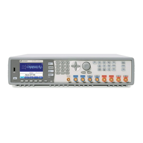
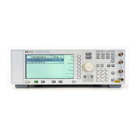
HP ESG Series User manual

User’s Guide
HP ESG and HP ESG-D Series Signal Generators
HP Part No. E4400-90142
Printed in USA
October 1998
Supersedes July 1998
© Copyright 1998 Hewlett-Packard Company

ii

Contents
iii
1. Preparing for Use
Installing the Signal Generator. . . . . . . . . . . . . . . . . . . . . . . . . . . . . . . . . . . . . . . . . . . . . . . . .1-2
Verifying Signal Generator Operation . . . . . . . . . . . . . . . . . . . . . . . . . . . . . . . . . . . . . . . . . . .1-8
2. Using Functions
Setting Frequency and Power Levels . . . . . . . . . . . . . . . . . . . . . . . . . . . . . . . . . . . . . . . . . . . .2-2
Setting Up Internally Generated Amplitude Modulation . . . . . . . . . . . . . . . . . . . . . . . . . . . .2-5
Setting Up Internally Generated Frequency Modulation . . . . . . . . . . . . . . . . . . . . . . . . . . . .2-7
Creating a Step Sweep and a List Sweep . . . . . . . . . . . . . . . . . . . . . . . . . . . . . . . . . . . . . . . . .2-9
Saving and Recalling an Instrument State. . . . . . . . . . . . . . . . . . . . . . . . . . . . . . . . . . . . . . .2-12
Enabling Options . . . . . . . . . . . . . . . . . . . . . . . . . . . . . . . . . . . . . . . . . . . . . . . . . . . . . . . . . . .2-13
3. Troubleshooting
If You Encounter a Problem. . . . . . . . . . . . . . . . . . . . . . . . . . . . . . . . . . . . . . . . . . . . . . . . . . . .3-2
Error Messages. . . . . . . . . . . . . . . . . . . . . . . . . . . . . . . . . . . . . . . . . . . . . . . . . . . . . . . . . . . . . .3-6
Error Message Format . . . . . . . . . . . . . . . . . . . . . . . . . . . . . . . . . . . . . . . . . . . . . . . . . . . . . . . .3-7
Error Message Types . . . . . . . . . . . . . . . . . . . . . . . . . . . . . . . . . . . . . . . . . . . . . . . . . . . . . . . . .3-8
0: No Error. . . . . . . . . . . . . . . . . . . . . . . . . . . . . . . . . . . . . . . . . . . . . . . . . . . . . . . . . . . . . . . . .3-9
-499 to -400: Query Errors . . . . . . . . . . . . . . . . . . . . . . . . . . . . . . . . . . . . . . . . . . . . . . . . . . .3-10
-399 to -300: Device-Specific Errors . . . . . . . . . . . . . . . . . . . . . . . . . . . . . . . . . . . . . . . . . . . .3-11
-299 to -200: Execution Errors . . . . . . . . . . . . . . . . . . . . . . . . . . . . . . . . . . . . . . . . . . . . . . . .3-20
-199 to -100: Command Errors . . . . . . . . . . . . . . . . . . . . . . . . . . . . . . . . . . . . . . . . . . . . . . . .3-42
201 to 702: Device-Specific Errors . . . . . . . . . . . . . . . . . . . . . . . . . . . . . . . . . . . . . . . . . . . . .3-48
Returning Your Signal Generator to HP. . . . . . . . . . . . . . . . . . . . . . . . . . . . . . . . . . . . . . . . .3-61
HP Sales and Service Offices. . . . . . . . . . . . . . . . . . . . . . . . . . . . . . . . . . . . . . . . . . . . . . . . . .3-62
4. Front and Rear Panel
Front Panel Overview . . . . . . . . . . . . . . . . . . . . . . . . . . . . . . . . . . . . . . . . . . . . . . . . . . . . . . . .4-2
Display Annotation. . . . . . . . . . . . . . . . . . . . . . . . . . . . . . . . . . . . . . . . . . . . . . . . . . . . . . . . . . .4-8
Rear Panel Overview . . . . . . . . . . . . . . . . . . . . . . . . . . . . . . . . . . . . . . . . . . . . . . . . . . . . . . . .4-12
5. Hardkey and Softkey Reference
AM. . . . . . . . . . . . . . . . . . . . . . . . . . . . . . . . . . . . . . . . . . . . . . . . . . . . . . . . . . . . . . . . . . . . . . . .5-2
Ampl . . . . . . . . . . . . . . . . . . . . . . . . . . . . . . . . . . . . . . . . . . . . . . . . . . . . . . . . . . . . . . . . . . . . .5-16
Amplitude . . . . . . . . . . . . . . . . . . . . . . . . . . . . . . . . . . . . . . . . . . . . . . . . . . . . . . . . . . . . . . . . .5-23
Arrow Keys . . . . . . . . . . . . . . . . . . . . . . . . . . . . . . . . . . . . . . . . . . . . . . . . . . . . . . . . . . . . . . . .5-24
Display Contrast Keys . . . . . . . . . . . . . . . . . . . . . . . . . . . . . . . . . . . . . . . . . . . . . . . . . . . . . . .5-25
FM. . . . . . . . . . . . . . . . . . . . . . . . . . . . . . . . . . . . . . . . . . . . . . . . . . . . . . . . . . . . . . . . . . . . . . .5-26
Freq. . . . . . . . . . . . . . . . . . . . . . . . . . . . . . . . . . . . . . . . . . . . . . . . . . . . . . . . . . . . . . . . . . . . . .5-41
Frequency . . . . . . . . . . . . . . . . . . . . . . . . . . . . . . . . . . . . . . . . . . . . . . . . . . . . . . . . . . . . . . . . .5-46
Help. . . . . . . . . . . . . . . . . . . . . . . . . . . . . . . . . . . . . . . . . . . . . . . . . . . . . . . . . . . . . . . . . . . . . .5-47
Hold. . . . . . . . . . . . . . . . . . . . . . . . . . . . . . . . . . . . . . . . . . . . . . . . . . . . . . . . . . . . . . . . . . . . . .5-48
Incr Set . . . . . . . . . . . . . . . . . . . . . . . . . . . . . . . . . . . . . . . . . . . . . . . . . . . . . . . . . . . . . . . . . . .5-49
I/Q . . . . . . . . . . . . . . . . . . . . . . . . . . . . . . . . . . . . . . . . . . . . . . . . . . . . . . . . . . . . . . . . . . . . . . .5-50
LF Out. . . . . . . . . . . . . . . . . . . . . . . . . . . . . . . . . . . . . . . . . . . . . . . . . . . . . . . . . . . . . . . . . . . .5-61
Local . . . . . . . . . . . . . . . . . . . . . . . . . . . . . . . . . . . . . . . . . . . . . . . . . . . . . . . . . . . . . . . . . . . . .5-75
Mod On/Off . . . . . . . . . . . . . . . . . . . . . . . . . . . . . . . . . . . . . . . . . . . . . . . . . . . . . . . . . . . . . . . .5-76
Mode . . . . . . . . . . . . . . . . . . . . . . . . . . . . . . . . . . . . . . . . . . . . . . . . . . . . . . . . . . . . . . . . . . . . .5-77
iv
Contents
Numeric Keypad . . . . . . . . . . . . . . . . . . . . . . . . . . . . . . . . . . . . . . . . . . . . . . . . . . . . . . . . . . . 5-78
Phase Modulation . . . . . . . . . . . . . . . . . . . . . . . . . . . . . . . . . . . . . . . . . . . . . . . . . . . . . . . . . . 5-79
Power Switch . . . . . . . . . . . . . . . . . . . . . . . . . . . . . . . . . . . . . . . . . . . . . . . . . . . . . . . . . . . . . . 5-95
Preset . . . . . . . . . . . . . . . . . . . . . . . . . . . . . . . . . . . . . . . . . . . . . . . . . . . . . . . . . . . . . . . . . . . . 5-96
Pulse. . . . . . . . . . . . . . . . . . . . . . . . . . . . . . . . . . . . . . . . . . . . . . . . . . . . . . . . . . . . . . . . . . . . 5-105
Recall . . . . . . . . . . . . . . . . . . . . . . . . . . . . . . . . . . . . . . . . . . . . . . . . . . . . . . . . . . . . . . . . . . .5-109
Return . . . . . . . . . . . . . . . . . . . . . . . . . . . . . . . . . . . . . . . . . . . . . . . . . . . . . . . . . . . . . . . . . . 5-112
RF On/Off. . . . . . . . . . . . . . . . . . . . . . . . . . . . . . . . . . . . . . . . . . . . . . . . . . . . . . . . . . . . . . . . 5-113
Save . . . . . . . . . . . . . . . . . . . . . . . . . . . . . . . . . . . . . . . . . . . . . . . . . . . . . . . . . . . . . . . . . . . .5-114
Sweep/List . . . . . . . . . . . . . . . . . . . . . . . . . . . . . . . . . . . . . . . . . . . . . . . . . . . . . . . . . . . . . . . 5-119
Trigger . . . . . . . . . . . . . . . . . . . . . . . . . . . . . . . . . . . . . . . . . . . . . . . . . . . . . . . . . . . . . . . . . . 5-135
Utility. . . . . . . . . . . . . . . . . . . . . . . . . . . . . . . . . . . . . . . . . . . . . . . . . . . . . . . . . . . . . . . . . . . 5-137
6. Options and Accessories
Signal Generator Options . . . . . . . . . . . . . . . . . . . . . . . . . . . . . . . . . . . . . . . . . . . . . . . . . . . . . 6-2
Signal Generator Accessories . . . . . . . . . . . . . . . . . . . . . . . . . . . . . . . . . . . . . . . . . . . . . . . . . .6-6
7. Operation
8. Safety and Regulatory
Safety Notes. . . . . . . . . . . . . . . . . . . . . . . . . . . . . . . . . . . . . . . . . . . . . . . . . . . . . . . . . . . . . . . . 8-2
Instrument Markings . . . . . . . . . . . . . . . . . . . . . . . . . . . . . . . . . . . . . . . . . . . . . . . . . . . . . . . . 8-3
General Safety Considerations. . . . . . . . . . . . . . . . . . . . . . . . . . . . . . . . . . . . . . . . . . . . . . . . . 8-4
Statement of Compliance . . . . . . . . . . . . . . . . . . . . . . . . . . . . . . . . . . . . . . . . . . . . . . . . . . . . .8-5
Warranty . . . . . . . . . . . . . . . . . . . . . . . . . . . . . . . . . . . . . . . . . . . . . . . . . . . . . . . . . . . . . . . . . .8-6
Assistance . . . . . . . . . . . . . . . . . . . . . . . . . . . . . . . . . . . . . . . . . . . . . . . . . . . . . . . . . . . . . . . . . 8-7
Certification . . . . . . . . . . . . . . . . . . . . . . . . . . . . . . . . . . . . . . . . . . . . . . . . . . . . . . . . . . . . . . . . 8-8
Declaration of Conformity. . . . . . . . . . . . . . . . . . . . . . . . . . . . . . . . . . . . . . . . . . . . . . . . . . . . . 8-9
Compliance with German Noise Requirements. . . . . . . . . . . . . . . . . . . . . . . . . . . . . . . . . . . 8-10
9. Specifications
Signal Generators Specifications . . . . . . . . . . . . . . . . . . . . . . . . . . . . . . . . . . . . . . . . . . . . . . . 9-2

User’s Guide 1-1
HP ESG and HP ESG-D Series Signal Generators
1Preparing for Use
This chapter contains procedures that show you how to install your signal generator, and
how to perform a functional check to verify signal generator operation.

Preparing for Use HP ESG and HP ESG-D Series Signal Generators
Installing the Signal Generator
1-2 User’s Guide
Installing the Signal Generator
This section contains procedures for properly installing your signal generator:
• checking the shipment
• installing front handles and rack flange kits
• meeting electrical and environmental requirements
• adjusting the display
• selecting the signal generator’s HP-IB address
• selecting the programming language
Checking the Shipment
1. Inspect the shipping container for damage.
Look for signs of damage such as a dented or torn shipping container, or cushioning
material that shows signs of unusual stress or compacting.
2. Carefully remove the contents from the shipping container and verify that your order is
complete. Refer to Table 1-1 and Table 1-2 for a list of items that are shipped standard
with the signal generator and for a list of options that you may also have ordered.
Table 1-1 Shipment Verification List
Part Number Item Description Option
Unique to Country AC Power Cable Standard
5063-9227 Front Handle Kit 1CN
5063-9214 Rack Flange Kit (without handles) 1CM
5063-9221 Rack Flange Kit (with handles) 1CP
E4400-90145 Manual Set for HP ESG-D Series Standard
E4400-90141 Manual Set for HP ESG Series Standard
E4400-90145 or
E4400 90141 Additional Manual Set OB1
E4400-90155 Service Guide 0BW, 0BX
E4400-90156 Component Level Information Guide 0BV, 0BX

HP ESG and HP ESG-D Series Signal Generators Preparing for Use
Installing the Signal Generator
User’s Guide 1-3
The following table describes the localized versions of the manuals that you will receive if
you have ordered the options listed. In most cases, a subset of the user’s information from
the manual listed is localized. These options are available at no charge at the time of your
purchase of the signal generator. (Because the localization of these manuals is begun after
the English version is written, the localized manuals will become available over a period of
time. You may not receive all of the manuals listed.)
Table 1-2 Shipment Verification List for Localized Manuals
Part Number Item Description Language Option
E4400-90172
E4400-90180
E4400-90187
E4400-90194
E4400-90201
HP ESG and ESG-D User’s Guide
Real-Time I/Q Baseband Generator Guide
Dual Arbitrary Waveform Generator Guide
DECT Guide
GSM Guide
Chinese AB2
E4400-90173
E4400-90181
E4400-90188
E4400-90195
E4400-90202
HP ESG and ESG-D User’s Guide
Real-Time I/Q Baseband Generator Guide
Dual Arbitrary Waveform Generator Guide
DECT Guide
GSM Guide
Chinese for Taiwan AB0
E4400-90174
E4400-90182
E4400-90189
E4400-90196
E4400-90203
E4400-90212
HP ESG and ESG-D User’s Guide
Real-Time I/Q Baseband Generator Guide
Dual Arbitrary Waveform Generator Guide
DECT Guide
GSM Guide
TETRA Guide
French ABF
E4400-90175
E4400-90183
E4400-90190
E4400-90197
E4400-90204
E4400-90210
HP ESG and ESG-D User’s Guide
Real-Time I/Q Baseband Generator Guide
Dual Arbitrary Waveform Generator Guide
DECT Guide
GSM Guide
TETRA Guide
German ABD
E4400-90176
E4400-90179
E4400-90184
E4400-90191
E4400-90198
E4400-90205
E4400-90208
E4400-90209
HP ESG and ESG-D User’s Guide
Bit Error Rate Test Guide
Real-Time I/Q Baseband Generator Guide
Dual Arbitrary Waveform Generator Guide
DECT Guide
PDC Guide
PHS Guide
GSM Guide
Japanese ABJ
E4400-90177
E4400-90185
E4400-90192
E4400-90199
E4400-90206
HP ESG and ESG-D User’s Guide
Real-Time I/Q Baseband Generator Guide
Dual Arbitrary Waveform Generator Guide
DECT Guide
GSM Guide
Korean AB1
E4400-90178
E4400-90186
E4400-90193
E4400-90200
E4400-90207
E4400-90211
HP ESG and ESG-D User’s Guide
Real-Time I/Q Baseband Generator Guide
Dual Arbitrary Waveform Generator Guide
DECT Guide
GSM Guide
TETRA Guide
Spanish ABE

Preparing for Use HP ESG and HP ESG-D Series Signal Generators
Installing the Signal Generator
1-4 User’s Guide
Installing Front Handles and Rack Mount Flanges
You can attach handles to the front of the signal generator to facilitate transportation of
the instrument. Handles are available in a kit which can be ordered when the signal
generator is purchased (Option 1CN), or at any time afterward. Assembly instructions are
included with the kit. The kit part number is listed in Table 1-3.
You can also rack mount the signal generator. Hardware is available in kits to install rack
mount flanges on the signal generator without or with handles. These kits can be ordered
when the signal generator is purchased (Options 1CM and 1CP), or at any time afterward.
Assembly instructions are included with the kits. The kit part numbers are listed in
Table 1-3.
Table 1-3 Front Handle and Rack Mount Flange Kits
Providing Adequate Ventilation
CAUTION Ventilation Requirements: When installing the product in a cabinet, the
convection into and out of the product must not be restricted. The ambient
temperature (outside the cabinet) must be less than the maximum operating
temperature of the product by 4 °C for every 100 watts dissipated in the
cabinet. If the total power dissipated in the cabinet is greater than 800 watts,
then forced convection must be used.
Cooling holes are located on the sides and bottom of the instrument cover and the rear
panel of the instrument. Do not allow these holes to be obstructed as they allow air flow
through the signal generator.
Option Description HP Part Number
Option 1CN Front Handle Kit 5063-9227
Option 1CM Rack Mount Kit without Handles 5063-9214
Option 1CP Rack Mount Kit with Handles 5063-9221

HP ESG and HP ESG-D Series Signal Generators Preparing for Use
Installing the Signal Generator
User’s Guide 1-5
Meeting Electrical and Environmental Requirements
Line Settings
CAUTION This product has an autoranging line voltage input. Be sure that the supply
voltage is within the specified range.
The available AC power source must meet the following requirements:
Voltage:
• 100/115 volts nominal (90-132 volt range)
• 230/240 volts nominal (198-254 volt range)
Frequency:
• for 100/115 volts: 50/60/400 Hz nominal
• for 230/240 volts: 50/60 Hz nominal
Power:
• 200 watts maximum
Verify that the power cable is not damaged and that the power source socket outlet
provides a protective earth contact.
WARNING This is a Safety Class 1 Product (provided with a protective earthing
ground incorporated in the power cord). The mains plug shall only
be inserted in a socket outlet provided with a protective earth
contact. Any interruption of the protective conductor inside or
outside of the product is likely to make the product dangerous.
Intentional interruption is prohibited.
CAUTION Always use the three-prong AC power cord supplied with this product.
Failure to ensure adequate earth grounding by not using this cord may cause
product damage.
Environment
This product is designed for use in the following environmental conditions:
• indoor use
• < 15,000 feet (4,572 meters) altitude
• 0 to 55 °C temperature, unless specified differently
• maximum relative humidity 80% for temperatures up to 31 °C, decreasing linearly to
50% relative humidity at 40 °C
CAUTION This product is designed for use in INSTALLATION CATEGORY II and
POLLUTION DEGREE 2, per IEC 1010 and 664 respectively.

Preparing for Use HP ESG and HP ESG-D Series Signal Generators
Installing the Signal Generator
1-6 User’s Guide
WARNING If this product is not used as specified, the protection provided by
the equipment could be impaired. This product must be used in a
normal condition only (in which all means for protection are intact).
Cleaning the Signal Generator
Clean the instrument cabinet using a damp cloth only.
Adjusting the Display Contrast
You can adjust the contrast of the display by pressing the decrease contrast key or
the increase contrast key . These keys are located on the front panel below the
display.
Pressing the decrease contrast key and holding it down causes the display background to
gradually darken in comparison to the text on the display. The minimum contrast setting
is not a completely black display. Some contrast between the background and the text will
still be visible.
Pressing the increase contrast key and holding it down causes the display background to
gradually brighten in comparison to the text on the display. If the background does not
appear to change, it is probably set to the maximum contrast.
Selecting Inverse Video
The normal display mode for the signal generator is dark text on a light background. To
change to inverse video (light text on a dark background), press Utility,Display and set
Inverse Video Off On to On. Inverse video is a persistent state; it is not affected by an
instrument preset or by a power cycle.
Adjusting the Screen Saver
You can increase the life expectancy of the signal generator’s display light by turning on
the screen saver. Leaving the display lit for long periods of time or turning the display on
and off frequently decreases the life of the bulb. With the screen saver on, the display light
is turned off after a defined period of time with no input to the front panel. The display
light turns on again when any front panel key is pressed or when a remote command is
sent.
The screen saver is set to off at the factory. You can turn it on by pressing Utility,Display,
Screen Saver Off On. Each time you press Screen Saver Off On the selection toggles between Off
and On.
You can adjust the screen saver mode to turn the light on and off or to turn both the light
and text on and off. Press Utility,Display,Screen Saver Mode. You can toggle between Light Only
and Light & Text. Setting the mode to Light Only turns the display light off but leaves the text
visible at a low intensity. To prevent the text from burning the display if you are leaving
the display unchanged for long periods of time, set the mode to Light & Text. This mode turns
off the display light and the text.

HP ESG and HP ESG-D Series Signal Generators Preparing for Use
Installing the Signal Generator
User’s Guide 1-7
The screen saver delay is set to 1 hour at the factory. You can view and change the delay by
pressing Screen Saver Delay in the same menu. The current screen saver delay is displayed in
the softkey label and also in the active entry area. To change the delay, enter a new value
using the numeric keypad and then press Enter, or rotate the front panel knob. The
acceptable range of delay values is 1 through 12 hours in 1 hour increments.
The screen saver settings do not change when Preset is pressed, nor when power to the
instrument is cycled.
Selecting the Signal Generator’s HP-IB Address
The signal generator’s HP-IB address is set to 19 at the factory. You can view and change
the address by pressing Utility,HP-IB/RS-232,HP-IB Address. The current HP-IB address is
displayed in the softkey label and also in the active entry area. To change the address,
enter a new value using the numeric keypad and then press Enter, or rotate the front panel
knob. The acceptable range of addresses is 0 through 30.
The HP-IB address is a persistent state; it is not affected by an instrument preset or by a
power cycle.
Selecting the Signal Generator’s Programming Language
The default programming language for the signal generator is Standard Commands for
Programmable Instruments (SCPI). You can change this language selection by pressing
Utility,HP-IB/RS-232,Remote Language. You can change this language selection by pressing
Utility,HP-IB/RS-232,Remote Language. The Remote Language menu allows you to select
between HP 8656/57-compatible language, HP 8648-compatible language, and SCPI
language. If you have an HP ESG-D Series Option UN8, the Remote Language menu
allows you to select between HP 8656/57-compatible language, HP 8657D language
(NADC digital modulation capability), HP 8657D language (PDC digital modulation
capability), and HP 8657J (PHS digital modulation capability). Press the softkey for the
selection that you desire.
You can also change the language selection by sending the appropriate command over
HP-IB. Refer to the programming guide for instructions for changing the language over
HP-IB.
You can set the signal generator to default to a selected language as a persistent state
(remains unchanged after an instrument preset or power cycle). Press Utility,
Power On/Preset,Preset Language. The Preset Language menu allow you to select between
SCPI, the HP 8656/57-compatible programming languages, and HP 8648-compatible
language. Press the softkey for the selection that you desire.

Preparing for Use HP ESG and HP ESG-D Series Signal Generators
Verifying Signal Generator Operation
1-8 User’s Guide
Verifying Signal Generator Operation
The operator’s check is appropriate as a daily functional check by users, or whenever the
integrity of the signal generator is in question. Use the operator’s check to verify proper
operation of the signal generator. The operator’s check does not ensure performance to
specifications. To verify specifications, refer to the calibration guide.
Operator’s Check
Perform the following tasks in order:
Power On the Signal Generator and Check for Error Messages
This procedure verifies that the signal generator powers up and that the internal
instrument check identifies no errors.
1. Turn power on to the signal generator by pressing the power switch. The green LED
will light. Let the instrument warm up for one hour.
2. Cycle the power to the signal generator. The green LED should again be lit and the
instrument will perform a check.
3. When the display is lit, check to see if the ERR annunciator is turned on.
4. If the ERR annunciator is turned on, review the error messages in the queue by pressing
Utility,Error Info. The first error message in the queue will be shown in the text area of the
display. Refer to Chapter 3, “Troubleshooting,” for information about the error message.
If there is more than one error message (each message will be designated as 1 of n),
press the View Next Error Message softkey until you have seen all of the messages.
5. When you have resolved all of the error messages, press Clear Error Queue(s) to delete the
messages. Then restart this procedure at step two.
Note: For instruments with Option 1E5, ERROR 514, Reference Oven Cold will occur
whenever the signal generator is first connected to AC line power. The OVEN COLD
annunciator and the ERR annunciator will both turn on. The OVEN COLD annunciator
will automatically clear after approximately 5 minutes. The error queue cannot be
cleared, however, until the OVEN COLD annunciator has turned off.
Verify Maximum Specified Power is Available at the Maximum Frequency
This procedure verifies that there are no unleveled power indications or error messages at
the maximum specified frequency and power level.
1. Calibrate the power meter with the power sensor. (Refer to the power meter’s manual
for assistance.)
2. Connect the power sensor to the signal generator’s RF OUTPUT connector as shown in
Figure 1-1.

HP ESG and HP ESG-D Series Signal Generators Preparing for Use
Verifying Signal Generator Operation
User’s Guide 1-9
Figure 1-1 Operator’s Check Equipment Setup
3. Preset the signal generator to the factory-defined conditions:
a. Press Utility,Power On/Preset and toggle Preset until Normal is highlighted.
b. Press the front panel Preset key.
4. Set the signal generator to its maximum specified frequency:
a. Press Frequency.
b. Use the numeric keypad to enter the signal generator’s maximum specified
frequency as shown in Table 1-4.
c. Terminate your entry by pressing the GHz softkey.
5. Set the signal generator to its maximum specified power level:
a. Press Amplitude.
b. Use the numeric keypad to enter the signal generator’s maximum specified power
level as shown in Table 1-4.
c. Terminate your entry by pressing the dBm softkey.
6. Toggle the front panel RF On/Off key to turn on RF power to the RF OUTPUT connector.
The display RF ON annunciator will turn on.
7. Verify that the power meter reads the maximum specified output power including the
power level accuracy limits.
8. Check to see if the UNLEVEL or ERR display annunciators have turned on. If these
annunciators are on, refer to the service guide for troubleshooting information.

Preparing for Use HP ESG and HP ESG-D Series Signal Generators
Verifying Signal Generator Operation
1-10 User’s Guide
Table 1-4 Frequency and Power Level Limits
1. The values provided are confidence levels only; they are
not specifications.
Instrument
Model
Maximum
Specified
Frequency
Maximum
Specified
Power
Power Level
Accuracy
Limits1
HP E4400B
HP E4430B 1 GHz +13 dBm ±0.7 dB
HP E4420B
HP E4431B 2 GHz +10 dBm ±0.7 dB
HP E4421B
HP E4432B 3 GHz +10 dBm ±1.0 dB
HP E4422B
HP E4433B 4 GHz +7 dBm ±1.0 dB

User’s Guide 2-1
HP ESG and HP ESG-D Series Signal Generators
2Using Functions
This chapter contains procedures that show you how to use some of the major functions of
your signal generator including setting frequency and power levels, setting up
modulations, creating step and list sweeps, saving and recalling instrument states, and
enabling options.

Using Functions HP ESG and HP ESG-D Series Signal Generators
Setting Frequency and Power Levels
2-2 User’s Guide
Setting Frequency and Power Levels
Using these procedures, you will learn how to:
• set the RF frequency
• set a frequency reference and a frequency offset
• set the RF output power level
• set an amplitude reference and an amplitude offset
To Set the RF Frequency
1. Turn on power to the signal generator: press the power switch, , so that the green
LED is on. The signal generator will perform an internal check.
2. Press the green Preset key. The signal generator will return to a set of factory-defined
conditions.
NOTE You can change the preset conditions to a user-defined instrument state.
However, for the purpose of these examples, use the factory-defined preset
state (the Preset Normal User softkey in the Utility menu must be set to Normal).
3. Observe the frequency area of the display (in the upper left-hand corner). It should
display the maximum specified frequency of your signal generator.
4. The signal generator is set to output an RF signal, however the RF On/Off key must be
set to On before the RF signal is available at the RF OUTPUT connector. Press RF On/Off.
Notice that the display annunciator changes from RF OFF to RF ON. The maximum
specified frequency is now being output at the RF OUTPUT connector.
5. Change the frequency to 700 MHz by pressing Frequency. The current RF frequency is
now displayed in the active entry area of the display. Using the numeric keypad, enter
700 and then press the MHz terminator softkey. The new 700 MHz RF frequency is now
displayed in the frequency area of the display and also in the active entry area.
6. Frequency is still the active function until you press another front panel function key.
Change the frequency again by pressing the up arrow key once. Each press of the up
arrow key increases the frequency by the increment value last set with the Incr Set key.
The increment value is displayed in the active entry area.
The down arrow works like the up arrow. Practice stepping the frequency up and down
in 1 MHz increments. Use the Incr Set key to change the increment value to 1 MHz, if
necessary.
7. You can also adjust the RF frequency using the front panel knob. As long as frequency is
the active function (the frequency is displayed in the active entry area), the front panel
knob will increase and decrease the RF frequency. Use the front panel knob to adjust
the frequency back to 700 MHz.

HP ESG and HP ESG-D Series Signal Generators Using Functions
Setting Frequency and Power Levels
User’s Guide 2-3
To Set a Frequency Reference and a Frequency Offset
The following procedure sets the RF output frequency as a reference frequency to which all
other frequency parameters are relative. The frequency initially shown on the display will
be 0 Hz (the frequency output by the hardware minus the reference frequency.) Although
the display changes, the frequency output does not change. Any subsequent frequency
changes are shown as incremental or decremental to 0 Hz.
1. Press Preset to return the signal generator to the factory-defined instrument state.
2. Set the RF frequency to 700 MHz.
3. Turn on frequency reference mode and set the current output frequency (700 MHz) as
the reference value. Press Freq,Freq Ref Set. The frequency displayed is 0 Hz (the
frequency output by the hardware, 700 MHz, minus the reference value, 700 MHz).
Notice that the REF indicator is turned on and the Freq Ref softkey has toggled to On.
4. Set the RF On/Off key to On. Notice that the display annunciator has changed from
RF OFF to RF ON. The RF frequency at the RF OUTPUT connector is 700 MHz.
5. Increment the output frequency by 1 MHz. Press the up arrow key. The frequency
display changes to show 1 MHz (the frequency output by the hardware,
700 MHz + 1 MHz, minus the reference frequency, 700 MHz) and the output frequency
changes to 701 MHz.
6. Enter a 1 MHz offset. Press the Freq Offset softkey and enter 1 MHz using the numeric
keypad and pressing the MHz terminator softkey. The frequency display shows 2 MHz
(the frequency output by the hardware, 701 MHz, minus the reference frequency,
700 MHz, plus the offset, 1 MHz.) Notice that the OFFSET indicator is turned on. The
frequency at the RF OUTPUT connector is still 701 MHz.
To Set the RF Output Power Level
1. Press Preset to return the signal generator to the factory-defined instrument state.
2. Observe the amplitude area of the display (in the upper middle of the display). It should
display −135 dBm. This is the normal preset RF output power level.
3. The signal generator is set to output an RF signal, however the RF On/Off key must be
set to On before the RF signal is available at the RF OUTPUT connector. Press RF On/Off.
Notice that the display annunciator changes from RF OFF to RF ON. The RF signal is
now being output at a −135 dBm level at the RF OUTPUT connector.
4. Change the power level to −20 dBm. Press Amplitude. The current power level is now
displayed in the active entry area of the display. Using the numeric keypad and the key,
enter −20 and then press the dBm softkey. The new −20 dBm RF output power is now
displayed in the amplitude area of the display and also in the active entry area.
5. Amplitude is still the active function until you press another front panel function key.
You can also change the amplitude using the up and down arrow keys and the front
panel knob. Practice changing the amplitude using these methods also.

Using Functions HP ESG and HP ESG-D Series Signal Generators
Setting Frequency and Power Levels
2-4 User’s Guide
To Set an Amplitude Reference and an Amplitude Offset
The following procedure sets the RF output power as an amplitude reference to which all
other amplitude parameters are relative. The amplitude initially shown on the display will
be 0 dB (the power output by the hardware minus the reference power). Although the
display changes, the output power does not change. Any subsequent power changes are
shown as incremental or decremental to 0 dB.
1. Press Preset to return the signal generator to the factory-defined instrument state.
2. Set the RF output power to −20 dBm.
3. Turn on amplitude reference mode and set the current output power (−20 dBm) as the
reference value. Press Ampl,More (1 of 2),Ampl Ref Set. The amplitude displayed is 0 dB
(the power output by the hardware, −20 dBm; minus the reference value, −20 dBm.)
Notice that the REF indicator is turned on and the Ampl Ref softkey has toggled to On.
4. Set the RF On/Off key to On. Notice that the display annunciator has changed from
RF OFF to RF ON. The power at the RF OUTPUT connector is −20 dBm.
5. Use the up arrow key to increase the output power by 10 dB. The amplitude display
changes to show 10 dB (the power output by the hardware, −20 dBm; +10 dBm; minus
the reference power, −20 dBm) and the output power changes to −10 dBm.
6. Enter a 10 dB offset. Press the Ampl Offset softkey and enter 10 dB using the numeric
keypad. The amplitude display shows 20 dB (the power output by the hardware,
−10 dBm; minus the reference power, −20 dBm; plus the offset, 10 dB). Notice that the
OFFS indicator is turned on. The power at the RF OUTPUT connector is still −10 dBm.

HP ESG and HP ESG-D Series Signal Generators Using Functions
Setting Up Internally Generated Amplitude Modulation
User’s Guide 2-5
Setting Up Internally Generated Amplitude
Modulation
Using this procedure, you will learn how to generate an amplitude-modulated signal with
the following characteristics:
• carrier frequency set to 1340 kHz
• power level set to 0 dBm
• AM depth set to 90%
• AM rate set to 10 kHz
Setting the Carrier Frequency
1. Preset the signal generator to the factory-defined instrument state.
2. Press the front panel Frequency key. Frequency becomes the active function and the
normal preset value for frequency is displayed in the active entry area.
3. Enter 1340 kHz using the numeric keypad and pressing the kHz terminator softkey. The
new carrier frequency is shown in the frequency area of the display. You should see
1.340 000 00 MHz.
Setting the Power Level
1. Press the front panel Amplitude key. Amplitude becomes the active function and the
normal preset value for amplitude is displayed in the active entry area.
2. Enter 0 dBm using the numeric keypad and pressing the dBm terminator softkey. The
new power level is shown in the amplitude area of the display. You should see 0.00 dBm.
Setting the AM Depth
1. Press the front panel AM key. The first level menu of softkeys is displayed.
2. Press the AM Depth softkey. AM depth becomes the active function and the normal preset
value for AM depth is displayed in the active entry area.
3. Enter 90% using the numeric keypad and pressing the %terminator softkey. The new
AM depth is displayed below the AM Depth softkey. You should see 90.0 % in the second
line of the softkey.
Setting the AM Rate
1. In the same AM menu, press the AM Rate softkey. AM rate becomes the active function
and the normal preset value for AM rate is displayed in the active entry area.

Using Functions HP ESG and HP ESG-D Series Signal Generators
Setting Up Internally Generated Amplitude Modulation
2-6 User’s Guide
2. Enter 10 kHz using the numeric keypad and pressing the kHz terminator softkey. The
new AM rate is displayed below the AM Rate softkey. You should see 10.0000 kHz in the
second line of the softkey.
Turning On Amplitude Modulation
The signal generator is now configured to output a 0 dBm, amplitude-modulated carrier at
1340 kHz with the AM depth set to 90% and the AM rate set to 10 kHz. The shape of the
waveform is a sinewave (notice that sine is the default for the AM Waveform softkey). Follow
these remaining steps to output the amplitude-modulated signal.
1. In the same AM menu, press the AM Off On softkey. AM toggles from Off to On. Notice,
also, that the AM display annunciator is turned on indicating that you have enabled
amplitude modulation.
2. Press the front panel RF On/Off key to toggle RF on. Notice that the display annunciator
changes from RF OFF to RF ON. The modulated signal is now available at the RF
OUTPUT connector.
Other manuals for ESG Series
2
This manual suits for next models
1
Table of contents
Other HP Pulse Generator manuals
Popular Pulse Generator manuals by other brands

Boston Scientific
Boston Scientific EMBLEM S-ICD user manual

Quantum Composers
Quantum Composers 9520 Series operating manual

Quantum Composers
Quantum Composers Sapphire 9212 specification

Tektronix
Tektronix PG502 instruction manual

Colby Instruments
Colby Instruments XT-100 Operating and programming manual

Digitimer
Digitimer NeuroLog NL405 Width/Delay user manual