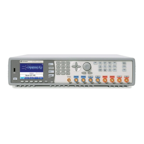
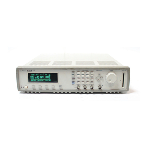
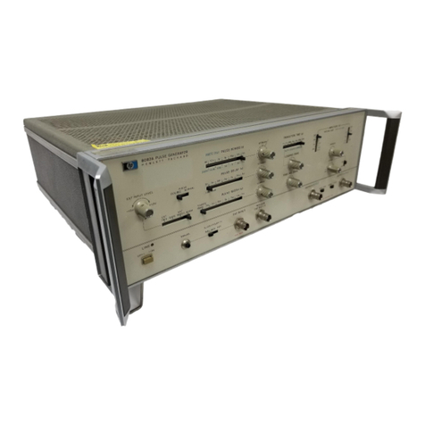
HP 8133A User manual

Service Guide
OTS
LIBRARY
\
HP
8133A
3
GHz
Pulse
Generator
HE'
part
N
O
.
08133
-
91021
Printed in
Germany
March
1994
Edition
1.1
E0394

Copyright
@
1994
Hewlett
-
Packard GmbH.
Herrenberger Str.
130
71034
B6blingen
Federal Republic of Germany
All
Rights Reserved. Reproduction,
adaptation
or
translation without prior
written permission is prohibited, except
as
allowed under the copyright laws.
Warranty
The information contained in this
document is subject
to
change without
notice.
Hmlettrtcckard
makes
no
warranty
of
any kind
with
regard
to
this
material,
inclzlding, but
not
limited
to,
the
implied
warranties
or
merchantibilityand
&nzss
for
a
particular
plcrpose
Hewlett
-
Packard shall not be liable for
errors contained herein
or
forincidental
or
consequential damages in connection
with the furnishing, performance,
or
use
of this material.
Complete product warranty information
is given in the User Guide.
Safety
This is a Safety Class
1
instrument
(provided with terminal for protective
earthing). Before applying power, verify
that the correctsafety precautions are
taken (see the following warnings). In
addition, note the external markings on
the instrument that are described under
Safety
Symbols.
Warninit
Before turning on the instrument,
you
must connect the protective earth
termina:, of the instrument
to
the
protective earth conductor of the (mains)
power cord. The mains plug
must
only be
inserted in a socket outlet with
a
protective earth contact.
Do
not negate
the protective action by using an
extension power cord without a
protecti,ve grounding conductor.
Grounding one conductor of a
two
-
conductor outlet is not sufficient
protection.
Service instructions are for trained
service :personnel.
?b
avoid dangerous
electric shock, do not perform any
service unless qualified
to
do
so.
Do
not
attempt internal service
or
aaustment
unless another person, capable of
rendering first aid and resuscitation,
is
present.
If
you energize this instrument using an
auto
-
transformer (for voltage reduction)
make sure that the common terminal is
connected
to
the earth terminal of the
power s~urce.
Whenever it is likely that the ground
protectitm is impaired, you must make
the instrument inoperative and secure it
against .anyunintended operation.
Do
not operate the instrument in the
presence of flammable gases
or
fumes.
Operation of any electrical instrument in
such an environment constitutes a
definite safety hazard.
Do
not install substitute parts
or
perform
any unauthorized modification
to
the
instrument.
Capacitors inside the instrument may
retain a charge even if the instrument is
disconnected from its source of supply.
Safety
Symbols
A
Instruction Manual symbol: The
instrument is marked with this symbol
when it is necessary for you
to
refer
to
the instruction manual in order to protect
against damage to the instrument.
5
Hazardous voltage symbol.
Earth terminal symbol: used
to
indicate a
circuit common connected
to
grounded
chassis.
Protected conductor symbol
WARNING
The Warning symbol calls attention
to
a
procedure, practice,
or
the like, which, if
not correctly performed
or
adhered
to,
could result in personal iMury
or
loss
of
life.
Do
not proceed beyond a Warning
symbol until the indicated conditions are
fully understood and met.
CAUTION
The Caution symbol calls attention
to
a
procedure, practice,
or
the like, which, if
not correctly performed
or
adhered
to,
could result in damage
to
or
destruction
of part or all of the equipment.
Do
not
proceed beyond a Caution symbol until
the indicated conditions are fully
understood and met.
Notice
Warranty
This Hewlett
-
Packard product has
a warranty against defects in
material and workmanship for a
period of one year from date of
shipment. During the warranty
period, Hewlett
-
Packard Company
will, at its option, either repair
or
replace products that prove
to
be
defective.
For
warranty service
or
repair,
this product must be returned
to
a
service facility designated by
Hewlett
-
Packard. The Buyer shall
pay Hewlett
-
Packard’s round
-
trip
travel expenses.
For
products returned
to
Hewlett
-
Packard for warranty
service, tkie Buyer shall prepay
shipping charges
to
Hewlett
-
Packard and
Hewlett
-
Packard shall pay
shipping charges
to
return the
product
to
the Buyer. However,
the Buyer shall pay all shipping
charges, duties and taxes for
products returned
to
Hewlett
-
Packard from another
country.
Hewlett
-
Packard warrants that
its
software and firmware designated
by Hewlett
-
Packard for use with
an instrument will execute its
programming instructions when
properly installed on that
instrument.
Hewlett
-
Packard does not warrant
that the operation of the
instrument software,
or
firmware,
will be uninterrupted
or
error free.
Limitation
of
Warranty Certification
The foregoing warranty shall not
apply
to
defects resulting from
improper
or
inadequate
maintenance by the Buyer,
Buyer
-
supplied software
or
interfacing,unauthoriized
modification
or
misuse, operation
outside of the environmental
specifications forthe product,
or
improper site preparation
or
maintenance.
No
other warranty
is
expressed
or
implied. Hewlett
-
Packard
specifically disclaims the implied
warranties
of
merchantability
andfitness
for
a particularpurpose.
Exclusive Remedies
The remedies supplied are the
Buyer’s sole and exclusive
remedies. Hewlett
-
Packard shall
not be liable
for
any direct,
indirect, special, incidental,
or
consequential damages, whether
based on con
-
tract,
tort
or
anyotherlegal theory.
Assistance
Product maintenance agreements
and other customer assistance
agreements areavailable for
Hewlett
-
Packard products.
For
any assistance, contact your
nearest Hewlett
-
Packard Sales
Office.
Hewlett
-
Packard Company
certifies that this product met its
published specifications at the
time of shipment.
Hewlett
-
Packard further certifies
that its calibration measurements
are traceable
to
the United States
Institute of Standards and
‘kchnology, to the extent allowed
by the Institute’s calibrating
facility, and
to
the calibration
facilities
of
other International
Standards Organization members.
About this edition
HP
Part Number
08133
-
91021
Printed in Germany
Edition
1.1
E0394
March 1994
iii

About
this
book
This book is
a
guide to testing, troubleshOoting and servicing the HP
8133A
3
GHz
Pulse Generator.
Introducing the HP
8133A
Pulse Generator
A
summary of the instrument options,frontpanel, interchannel timing
relationships, and using the frontpanel Vernier Keys, plus Installation
instructions,
with
details of setting the line voltage.
HP
8133A
Pulse Generator Specifications
The HP
8133A
Pulse Generator’swarranted specificationsand other
characteristics.
Testing the
HP
8133A
Pulse Generator
Performance
and
Verification tests for testing the instrument.
Troubleshooting
A
series
of
flowcharts to assist troubleshootingin the Power Supplies
down to component level, plus general tests to establish the general
area
of
a fault.
Replacing Assemblies
A
guide
to
removing and replacing the main assemblies of the
HP
8133A
Pulse Generator.
Replaceable Parts
Lists
of
parts that can be replaced in the HP
8133A
Pulse Generator.
Theory
of
Operation
Functional description
of
the HP
8133A
Pulse Generator
PC
boards.
Making Adjustments
Information on adjustments and recalibration
of
the HP
8133A
Pulse
Generator.
CLIP
Component level information package.
iv

Contents
1
.
Introducingthe
Hp
8133A
Pulse Generator
Summary
of
HP 8133A Models
............
1
-
1
HP 8133A
.....................
1
-
1
HP 8133A Option 001
................
1
-
1
HP 8133A Option 002
................
1
-
1
HP 8133A Option
003
................
1
-
1
Frontpanel Overview
.................
1
-
2
0
.........................
1
-
2
0
.........................
1
-
2
@
.........................
1
-
2
@
.........................
1
-
2
@
.........................
1
-
2
0
.........................
1
-
2
@
.........................
1
-
2
@
.........................
1
-
3
Active Parameter
..................
1
-
3
Mode keys
.....................
1
-
3
Parameter keys
...................
1
-
3
Control keys
....................
1
-
3
Using the keys
...............
1
-
5
Summary
.....................
1
-
5
Example
-
Adjusting the Frequency
.........
1
-
5
1
-
6
Initial Inspection
..................
1
-
6
Power Requirements and Line Voltage Selection
...
1
-
7
Power Requirements
...............
1
-
7
Selecting the Line Voltage and Replacing the Fuse
.
1
-
7
Power
Cable
....................
1
-
8
Ventilation Requirements
..............
1
-
9
Mounting Hardware
................
1
-
9
Q
.........................
1
-
2
Interchannel Timing relationships
...........
1
-
4
Installing the HP 8133A Pulse Generator
........
2
.
E€P
8133A
Pulse Generator Specifications
TIMEBASE
......................
2
-
1
Internal Clock
...................
2
-
1
External Clock
...................
2
-
1
External Input
..................
2
-
1
External Frequency Counter
...........
2
-
2
External Divide
.................
2
-
2
TRIGGER
......................
2
-
2
Timing
.......................
2
-
2
Output Levels
...................
2
-
2
PULSE and PULSE/DATA
...............
2
-
3
2
-
3
PULSE Timing (Channel
1
and
Option
003
Channel 2)
.
Contents-1

PULSE Frequency(0ption 003 Channel
2)
......
2
-
3
PULSE.'DATA Timing (Option 002 Channel
2)
.....
2
-
4
Output Levels
...................
2
-
4
A
.....
.................
2
-
4
Output Modes
...................
2
-
5
HP
-
IB Capabilities
..................
2
-
5
Additional Features
..................
2
-
5
Non
-
volatile Memory
................
2
-
5
Rearpanel Connectors
.................
2
-
6
Channel
1
Input
&
Output
..............
Channel
2
Input
&
Output
..............
Start/Stop Input
..................
2
-
6
2
-
6
A
......................
2
-
6
2
-
6
A,-
....
....
.............
2
-
6
General Iinformation
.................
2
-
7
Operating Environment
...............
2
-
7
Power Requirements
................
2
-
7
Weight
.......................
2
-
7
Dimensions
(H
x
W
x
D)
................
Ventilatlon Requirements
..............
2
-
7
Acoustic Noise Emission
..............
2
-
7
Recalibration Period
................
2
-
8
Declaration of Conformity
..............
2
-
8
Supplementary Information
.............
2
-
8
2
-
7
3
.
Testing tlhe
Hp
8133A
Pulse Generator
Recommended Test EauiDment and Accessories
.....
3
-
1
..
......................
3
-
2
Tests
........................
3
-
2
Equipment
.....................
3
-
2
Internal Clock
-
Low Frequency Performance
.....
3
-
3
ivider Verification
............
3
-
3
quency Counter Performanee
......
3
-
4
Low
]Frequency
..................
3
-
4
External Divider Verification
............
3
-
5
External Frequency Counter Performance
......
3
-
5
High Frequency
.................
3
-
5
I
Clock
-
High Frequency Performance
....
3
-
6
......................
3
-
7
Tests
........................
3
-
7
Set.up
.......................
3
-
7
Equipment
.....................
3
-
7
Transition Time Performance
............
3
-
7
Risetime
.....................
3
-
8
F'alltiine
.....................
3
-
9
Dutycyele Verification
...............
3
-
9
Level Verification
..................
3
-
9
Outputs
.......................
3
-
10
Tests
........................
3
-
10
Equipment
......................
3
-
10
Delay Performance
.................
3
-
11
Extended Delay Performance
............
3
-
13
Contents
-
2

Inter
-
Channel Delay Performance (Options 002
8z
003
only)
......................
3
-
14
Width Performance
.................
3
-
16
Dutycycle Verification
...............
3
-
18
Level Performance
.................
3
-
19
Minimum Amplitude
...............
3
-
19
Maximum Amplitude
...............
3
-
19
Level Window Performance
.............
3
-
20
Maximum High
-
level
...............
3
-
20
Minimum Low
-
level
................
3
-
20
Overshoot and Ringing Performance
.........
3
-
21
Transition Time Performance
............
3
-
22
Risetime 10
-
90%
.................
3
-
22
Risetime 20
-
80%
.................
3
-
23
Falltime 20
-
80%
.................
3
-
23
Falltime 10
-
90%
.................
3
-
23
Jitter Performance
.................
3
-
24
Data Performance
.................
3
-
25
32BITRZ
....................
3
-
26
32 BIT
NRZ
...................
3
-
28
4
.
Troubleshooting
Troubleshooting the Power Supplies
..........
4
-
1
Using the Flowcharts
................
4
-
1
Unit not Operating
.................
4
-
3
Power Main board
..................
4
-
4
4
-
5
4
-
6
4
-
7
4
-
8
4
-
9
Power
-
on Reset Circuit Faulty
............
Fan Control Circuit Faulty
..............
-2OV
/
1.OA
No
Output or Wrong Voltage
.......
+
15V
/
1.8A
No
Output or Wrong Voltage
......
-
15V
/
1.1A
No
Output or Wrong Voltage
.......
+5.1V
/
2.7A
No
Output or Wrong Voltage
......
4
-
10
-5.1V
/
2.5A
No
Output or Wrong Voltage
......
4
-
11
-4.5V
/
3.5A
No
Output or Wrong Voltage
......
4
-
12
Power Control board
.................
4
-
13
Reference Voltages Faulty
..............
4
-
14
-2OV
/
1.OA
No
Output or Wrong Voltage
.......
4
-
15
+
15V
/
1.8A
No
Output
or
Wrong Voltage
......
4
-
16
-15V
/
1.1A
No
Output or WrongVoltage
.......
4
-
17
+5.1V
/
2.7A
No
Output or Wrong Voltage
......
4
-
18
-5.1V
/
2.5A
No
Output or Wrong Voltage
......
4
-
19
-4.5V
/
3.5A
No
Output or Wrong Voltage
......
4
-
20
Understanding the Self
-
Test Facility
..........
4
-
21
Troubleshooting Faulty Assemblies
...........
4
-
22
Trigger Output Check
................
4
-
22
Connecting the Test Equipment
..........
4
-
22
Performing the Test
................
4
-
22
Checking the Channel Link
.............
4
-
23
Preparing for the Test
...............
4
-
23
Testing the Channel Link
.............
4
-
24
Timing Board Output Check
.............
4
-
25
Connecting the Test Equipment
..........
4
-
25
Width Board Output Path
.............
4
-
26
Option 1 Fitted
...................
4
-
26
Option
2
Fitted
...................
4
-
26
Contents
-
3

Testing the Channel
2
Link
...........
Data
Board Output Path
............
5
.
Replacing Assemblies
Removing the top and side panels
Removing the shield
.................
...........
Removing the card cage and
its
assemblies
.......
Removing the card cage cover
............
Removing the frontpanel and
A1
keyboard
......
Separating the
A1
keyboard assembly from the
frontpanel
...................
Removingthe card cage
...............
Removing the card cage fan
.............
Removing the channel link block
..........
Removing the board keepers
............
Removing the channel
2
assembly. channel
1
assembly.
and timing assembly
...............
Removing the
A2
Motherboard assembly
.......
Reassembling the card cage and its assemblies
.....
Assembly replacement
...............
Replacing the channel block
.............
Replacing the
A1
keyboard assembly
.........
Replacing the card cage cover. shield and panels
...
Removing the rear panel
..............
Removing the
A3
MPU assembly and the
A4
power
comrol assembly
................
Removing the power supply cage and line switch
...
Removing the
A12
motherboard
...........
Disconnecting the
A14
main power assembly
.....
Removing the fan and line filter assembly
......
Disconnecting the line filter
.............
Removing the line switch plunger unit
........
Removing the transformer assembly
.........
Removing the
A14
main power assembly
.......
Reassembly
.....................
Removing the power supply and MPU assemblies
....
6
. Replaceable
Ruts
.
HP
8133A
Replaceable Parts List
...........
HP
8133A
Option
001
Replaceable Parts List
......
HP
8133A
Option
002
Replaceable Parts List
......
HP
8133A
Option
003
Replaceable Parts List
......
HP
8133A
Exchange
Parts
List
............
7. Theory
of
Operation
Overview
......................
Microprocessor (CPU)
.
A3
.............
Timing Board
.
A5
.................
Width 13oard
.
A7
..................
Data
Board
.
A6
(Optional)
Power Supply Unit
.
A4, A14
.............
............
Power Input
...................
Power Main Board
................
Power Control Board
...............
Power Outputs
..................
4
-
26
4
-
26
5
-
4
5
-
4
5
-
5
5
-
5
5
-
6
5
-
7
5
-
7
5
-
9
5
-
10
5
-
11
5
-
12
5
-
13
5
-
13
5
-
13
5
-
14
5
-
14
5
-
15
5
-
15
5
-
16
5
-
16
5
-
17
5
-
18
5
-
19
5
-
19
5
-
20
5
-
22
5
-
22
5
-
23
5
-
23
6
-
2
6
-
12
6
-
13
6
-
14
6
-
14
7
-
1
7
-
2
.
7.2
7
-
2
7
-
3
7
-
3
7
-
3
7
-
3
7
-
4
7
-
4
Contents4

Microprocessor Board (CPU)
..............
7
-
5
Microprocessor Interface
.
1
............
7
-
6
Clock Generation
.
3A
...............
7
-
6
Address Decoding
.
3A
...............
7
-
6
Device Bus Timing and Wait State Generation
.
3B
.
.
7
-
7
DTACK Generation
.
3B
...............
7
-
7
RAM
-
3D
.....................
7
-
8
ROM
-
3D
.....................
7
-
8
7
-
8
Interrupt control and LAB/DIAGjumpers
.....
7
-
8
Timing generation
................
7
-
8
Multi
-
Functional Peripheral
.
3B
...........
LAB
-
I0
.....................
7
-
9
Device Bus Interface
.
3D
..............
7
-
9
HP
-
IB Interface
.
3C
................
7
-
9
Keyboard Controller
.
3C
..............
7
-
9
Display Control
.
3C
................
7
-
9
Frequency Counter
.
3C
...............
7
-
10
Serial
I/O
......................
7
-
10
Reset and Battery Backup
.
3A
...........
7
-
10
Signal Description
.................
7
-
11
Address Map
....................
7
-
14
Timing Board
.
A5
..................
7
-
17
YIG Oscillator
...................
7
-
18
Delay block
....................
7
-
18
Variable Delay
..................
7
-
18
Switched Delay
..................
Shaping Amplifier
................
7
-
19
Frequency Counter
.................
7
-
20
Width Board
.
A7
...................
7
-
20
Variable Pulse Width Generation
...........
7
-
21
The Pulseformatter
.................
7
-
21
The Output Amplifier
................
7
-
21
Data Board
.
A6
...................
7
-
22
The Multiplexer:
..................
7
-
22
The Data Generator:
................
7
-
22
The PLL
......................
7
-
23
The Output Amplifier
................
7
-
23
Bitstream Trigger Retiming
.............
7
-
23
Power Supply Unit
.
A4,
A14
.............
7
-
24
Power Input
....................
7
-
25
Power Main Board
.................
7
-
25
+
15
V
Regulation
.................
7
-
25
Control Power
+
UB
................
7
-
26
Power-on Reset
...................
7
-
26
Fan
Control
....................
7
-
26
Power Control Board
................
7
-
27
Bias and Reference Voltages
.............
7
-
27
Control Circuits
..................
7
-
27
+
15
V
control
...................
7
-
27
Voltage Control
..................
7
-
27
Highbow Tapping Path Control
...........
7
-
27
Foldback Current Limitation
............
7
-
28
+5.1V
Control
...................
7
-
28
-4.W
Control
....................
7
-
28
7
.
19
Contents4

8.
A.
Component Level Information Package
Making a.djustmentsto the
HP
8133A
Pulse Generator
Index
Contents
-
6

Figures
1.1
.
HP 8133A Frontpanel overview
...........
1
-
2
1.2
.
HP 8133A Interchannel Timing Diagram
.......
1
-
4
1.3
.
Line Voltage Switch Assembly
............
1
-
8
1.4
.
Power Cables
.
Plug Identification
..........
1
-
8
3.1
.
Internal Clock Low Frequency Test Set
-
up
......
3
-
3
3.2
.
External Frequency Counter Low Frequency Test
3.3
.
External Frequency Counter High Frequency Test
3.4
.
Internal Clock High Frequency Test Set
-
up
......
3
-
6
3.5
.
Transition Time Test Set
-
up
........
3
-
7
3.6
.
Risetime
-
100ps/div
...........
3
-
8
Set
-
up
.....................
3
-
4
Set
-
up
.....................
3
-
5
3.7
.
Channel Delay Test Set
-
up (Channel
1)
....
3.8
. .
00
ns/div, DELAY
=
25.0000 ns
........
3.9
.
At+5
:
5.00 ns/div, DELAY
=
25.0000 ns
3.10
.
Ats
:
5.00 ns/div, DELAY
=
25.0000 ns
3.11
.
Inter
-
Channel Delay Test Set
-
up
...........
3.12
.
Atlc
:
1.00 ns/div DELAY
=
16.0000 ns
........
3.13
Atlc.g
:
1.00 ns/div Delay
=
16.0000ns
.
1
.
00
ns/div
.................
3.14
.
3.15
.
Channel Width Test Set
-
up
..........
ax
:
2.00 ns/div
...............
3.16
.
3.17
.
Maximum Amplitude
:
500
mV/div
3.18
.
Positive Edge Overshoot and Ringing
.........
3.19
.
Risetime 10
-
90%
..................
3.20
.
am
..................
3.21
.
Channel Data Test Set
-
up
.......
4.1
.
Functional Block Diagram of the HP 8133A Pulse
Generator Power
Supplies ............
4.2
.
Block Diagram of the Power Supplies Showing Power
Connections
..................
4.3
.
Unit Shows No Signs of Operating
..........
4.4
.
Power
-
on Reset Not Working, or Period Too Long or Too
Short
......................
4.5
.
Flowchart for Tracing Common Faults in Fan Control
Circuit
.....................
4.6. Flowcharts for Tracing Common Faults in -2OV
Regulator
....................
4.7
.
Flowcharts for Tracing Common Faults in
+
15V
Regulator
....................
4.8
.
Flowcharts
for
Tracing Common Faults in -15V
Regulator
....................
4.9
.
Flowcharts for Tracing Common Faults in
+5.1V
Regulator
....................
.......
.......
.
........
.........
3
-
11
3
-
12
3
-
12
3
-
;3
3
-
14
3
-
15
3
-
15
3
-
16
3
-
16
3
-
17
3
-
20
3
-
21
3
-
23
3
-
25
3
-
26
4
-
2
4
-
2
4
-
3
4
-
5
4
-
6
4
-
7
4
-
8
4
-
9
4
-
10
Contents
-
7

4.10
.
Flowcharts for Tracing Common Faults in
-5.1V
4.11
.
Flowcharts for Tracing Common Faults in
-4.5V
Regulator
....................
Regulator
....................
4.12
.
Flowchart for Tracing Reference Voltage Faults
....
Regulator
....................
Regulator
....................
Regulator
....................
Regulator
....................
4.19
.
Channel1 Links and Outputs
4.20 .
Setup for Testing the Trigger Output
.........
4.22 .
Channel Block Link Configurations
4.24
.
Width Eloard Output Path Waveform
.........
4.25
.
Data
Bclard Output Path Waveform
4.13 .
Flowchart for Tracing Common Faults in
-2OV
Regulator
4.14
.
Flowchart for Tracing Common Faults in
+
15V
4.15 .
Flowchart for Tracing Common Faults in
-
15V
Regulator
4.16
.
Flowchaut for Tracing Common Faults in
+5.1V
4.17
.
Flowchaut for Tracing Common Faults in
-5.1V
4.18
.
Flowchart for Tracing Common Faults in
-4.5V
.............
4.21 .
HP
8133A
Pulse Generator Trigger Output Waveform
.
4.23 .
Setup
for
Testing the Width Board Output
......
.........
.........
5.1 .
Sequence of operations
5.2 .
Plan view of instrument
..............
5.3 .
Card cage assembly locations
5.4 .
Frontpanel internal connections
...........
5.5
.
Shield securing screws
5.6 .
Connea;or ribbon location
..............
5.7
.
A1
Keyboard assembly securing screws
.......
5.8 .
A1
keyboard and frontpanel separation
.......
5.9
.
Screws securing card cage
to
right hand chassis wall
.
...................
...............
............
...............
5.10 .
Remove the card cage from the chassis
5.12 .
Channel block link configurations
5.13 .
Location of hexagonal securing nuts
5.14
.
Channel block securing screws
5.15 .
Relay box connectors
5.16 . A2
motherboard removal
5.17
.
Top trim replacement
5.18
.
Rear panel removal
.................
5.19 .
Line switch and power supply cage removal
.....
5.20 . A12
Motherboard removal
.............
5.21 . J6
and
57
location and removal
...........
5.22
.
Fan
ass.
embly securing screws
A14
side
.......
5.24
.
Line input filter and transformer connections
.....
5.25
.
Line switch plunger unit securing bracket
......
5.26 . A14
securing screws
................
7.1
.
Block Diagram of the HP
8133A
Pulse Generator
...
7.2
.
Functional Block Diagram of the
CPU
and the
Keyboard and Display Board
...........
7.3 .
Functional Block Diagram of the Timing Board
....
7.4
.
Functional Block Diagram of the Width Board
....
7.5 .
Functional Block Diagram of the
Data
Board and the
PLL,
......................
.......
5.11
.
Card cage fan
..........
.........
...........
................
..............
................
5.23
.
Fan
ass.
embly securing screws
A3
side
........
4
-
11
4
-
12
4
-
14
4
-
15
4
-
16
4
-
17
4
-
18
4
-
19
4
-
20
4
-
22
4
-
22
4
-
23
4
-
24
4
-
25
4
-
25
4
-
27
5
-
1
5
-
2
5
-
2
5
-
3
5
-
4
5
-
5
5
-
6
5
-
7
5
-
7
5
-
8
5
-
9
5
-
10
5
-
11
5
-
11
5
-
12
5
-
13
5
-
15
5
-
16
5
-
17
5
-
18
5
-
19
5
-
19
5
-
20
5
-
21
5
-
22
5
-
23
7
-
1
7
-
5
7
-
17
7
-
20
7
-
22
Contents
-
8

7.6
.
Functional Block Diagram
of
the HP
8133A
Pulse
7.7
.
Block Diagram
of
the Power Supplies Showing Power
Generator Power Supplies
............
7
-
24
Connections
..................
7
-
24
Contents
-
9

1.1
.
Line Voltage Ranges
................
1
-
7
1.2
.
Line Voltage and Fuse Selection
...........
1
-
7
1.3
.
Mounting Accessories
................
1
-
9
3.1
.
Recommended Test Equipment
...........
3
-
2
3.2
.
Recommended Accessories
.............
3
-
2
3.3
.
Output Test Summary
................
3
-
10
4.1
.
Self
-
Test Messages and Their Meanings
........
4
-
21
4.2
.
Fatal Self
-
Test Messages and Their Meanings
.....
4
-
21
5.1
.
Assemblies Indentification 'lhble
...........
5
-
3
5.2
.
Line Filter Connections
...............
5
-
21
6.1
.
Standard Replaceable Parts List
...........
6
-
2
6.2
.
Replaceable Parts List
.
Option 001
..........
6
-
12
6.3
.
Replaceable Parts List, Option 002
..........
6
-
13
6.4
.
Replaceable Parts List, Option 003
..........
6
-
14
6.5
...........................
6
-
14
7.1
.
Address Ranges
...................
7
-
6
7.2
.
Other a.ddressdecode signals
............
7
-
7
7.3
.
Wait state signals
..................
7
-
7
7.4
.
MFP I/O Lines
....................
7
-
8
7.5
.
ASIC Divider Specifications
.............
7
-
18
7.6
.
Delay Line Nominal Lengths
............
7
-
19
7.7
.
Shaping Amplifier Specifications
...........
7
-
19
7.8
.
Freque:ncyCounter Key Specifications
........
7
-
20
Contents10

1
Introducing the
HP
8133A
Pulse Generator
This chapter contains the following information:
m
A
summary HP 8133A Pulse Generator models currently available
m
An overview
of
the front panel
rn
Interchannel Timing relationships
rn
How to use the Vernier keys
rn
Installingthe HP 8133A Pulse Generator
Summary
of
HP
8133A
Models
HP
81338
HP
81338 Option 001
HP
81338 Option
002
HP
81338 Option 003
Single
-
channel
3
GHz
Pulse Generator.
Selectablevariable delay
OR
pulse
-
width.
Single
-
channel 3 GHz Pulse Generator.
Simultaneouslyvariable delay
AND
pulse
-
width.
Dual-channel3
GHz
Pulse Generator.
Channel
1
same
as
HP 8133A Option
001
Channel
2
PULSE/DATA Channel:
Selectable: Divided Squarewave
OR
32
-
Bit programmable data
OR
PRBS
223-1
Dual
-
Channel3
GHz
Pulse Generator.
Channel
1
same
as
HP
8133A
Option
001
Channel
2
same
as
HP 8133A

Frontpanel Overview
J
I
c
.
. .
.
. .
.
,
.
.
.
. . .
,
,,,._
.
.
.
,
.
.
.
.
.
.m
\
0-
0
6
Figure
1
-
1.
HP
8133A
Frontpanel overview
The
Display
shows the
active parameter
and one other parameter.
Choose the
active parameter
using the
Mode/ParameterKeys
Edit the
active ]parameter
using the
DATA
editing fm~ctionsare indicated Keys. The
32
BIT
ption
002
only).
Channel
1
controls and output connectors.
Channel controls and output connector.
Optional Ch ctors.
(Option
002
0
Use the keys to control the instrument frequency.
@
Use the keys to save and recall instrument settings.
1
-
2
introducing the HP
8133A
Pulse Generator

8
Active
Parameter
Mode keys
Parameter keys
Control keys
Use the Control
keys
to
control the output modes.
The active parameter is the parameter which can be adjusted using
the
LED
in the
parameter key
is lit.
keys.
It
is the
bright
parameter on the display, and the
Mode keys toggle between different operating modes. They are
located in the upper row
of
keys, see Figure
1
-
1.
The
LEDs
above the
key indicate which mode is selected.
Parameter keys activate a parameter on the display. They are located
in the upper row
of
keys, see Figure
1
-
1.
Press once to activate the
selected parameter indicated by the
LEDs
above the key. Press again
to select and activate the alternative parameter. The
LED
in the key
indicates that the parameter is active in the display.
Control keys toggle an output mode on or
off.
They are located in the
lower row
of
keys, see Figure
1
-
1.
The
LED
in the key is lit when the
mode is on.
Introducing the
HP
8133A
Pulse
Generator
1-3

Interchannel
Timing
relationshipbs
TRIGGER
Output
I
PULSE/DRTA Channe
1
2
Output
I
Variable Delay
I
r-1
r------
m
12
to
18
ns
Fi
xed
50%
Duty
-
cyc
I
e
SQUARE mode
I
u
-
L
C’ar
1
ab
1
e
De
I
ay Variable
Width
OPTION
001:
-
-
5
to
+5
ns
---+
0.15
to
ID
ns
PULSE Channel
1
Output
(Option
001)
PULSE mode
r
1
L’ar
I
ab
1
e
De
1
ay
-&+
-5
to
115
ns
Fi
xed
58%
Duty
-
cyc
1
e
~~
SQUARE mode
1,r
PULSE/DATA Channe
1
2
Output
(Option 882)DATA NRZ mode
TRIGGER
Output
I
I
1
BIT
€2
mode
(Option
OD2
only)
2
ns typical Var
I
ab
1
e Width
OPTION
883:( includes
OPTION
001);
-
B.15
to
1B
ns
PULSE Channel
2
Output
I1
PULSE mode
I
?
a
to
10
ns Fixed
50%
Duty
-
cycle
I
I
SQUARE mode
I
I
Figure
1
-
2.
HP
8133A
Interchannel Timing Diagram
1-4
Introducing
the
HP
8133A
Pulse
Generator

4-
ROTAUE
REPWT
0-U
+l
Summary
Use the keys to adjust the value
of
the active parameter.
Only one parameter can be active at
a
time, although two may be
visible on the display. The active parameter
is
the
bright
parameter on
the
display.
indicated by LEDs in and above
a
mode/parameter key
(See
Each pair of keys controls the corresponding digit of the parameter:
Figure
1
-
1).
Press once to increment digit by
1
Press once to decrement digit by
1
0J
(ID
Hold
a
key down to auto
-
repeat and smoothly change
a
parameter.
If
you hold two neighbouring keys down, the auto
-
increment (or
decrement) steps
at
a
rate of three times the lower digit.
A
decimal
-
carry operates when you change
a
digit from
9
to
0
or from
0
to
9.
Leading zeroes are not displayed, but the vernier keys can
still be used to increase/decrease the “digit”. If you try to adjust a
parameter outside its valid range, you
will
see
an
error message telling
you the parameter limit.
Example
-
Adjusting
the
Frequency
After recalling the Standard settings, the display shows the standard
Period and Channel
1
Width settings. The Period is the active
parameter and appears brighter:
Pet-
38.
.so:!:
1
:
LsJ1
tj
150
ps
1.
Press
(FREQ~PERIOD)
to activate the Frequency
parameter.
The PERIOD LED switches
off
and the FREQLED switches on. The
LED in the key remains
on,
indicating that this
is
still the active
parameter. The display now shows the timebase Frequency:
Ft-rq
:3:::,
8
MH=
1
:
14
i
150
ps
Introducing the
HP
8133A
Pulse
Generator
1-5

2.
Use the keys to increase the timebase Frequency to
1
.OOOO
GHz:
,--.
CURSOR
+
FILL
0-1
+E
Installingthe
HP
8133A
Pulse Generator
Initial Inspection
Inspect the shipping container for damage. If the container
or
cushioning material
is
damaged, keep
it
until the contents of the
shipment have bleen checked for completeness and the instrument
has
been verified both mechanically and electrically.
To
avoid hazardouselectric shock, do not perform electrical
tests
when there are signs
of
shipping damage to any part
of
the
instrument’souter covers or panels.
Warning
9
If
the contents are incomplete,
or
there
is
mechanical damage,
or
if
the instrument does not
pass
the Performance Tests in Chapter
3,
notify the nearest Hewlett-Packard office. Keep the shipping materials
for inspection
by
the carrier. The HP office
will
arrange for repair or
replacement without awaiting settlement.
1-6
Introducing
the
HP
8133A
Pulse Generator
Table of contents
Other HP Pulse Generator manuals