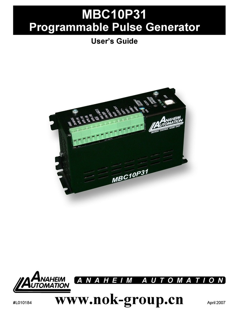
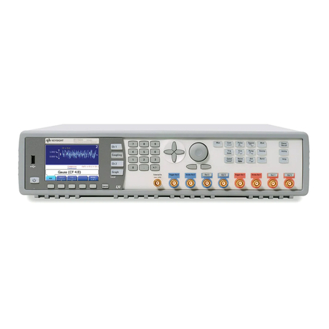
HP 8110A User manual

The test & measurement
equipment you need at
the price you want.
Alltest carries the world’s largest selection of
used/refurbished benchtop test & measurement
equipment at 50% the price of new.
O
Our equipment is guaranteed working, warrantied, and
available with certified calibration from our in-house staff
of technicians and engineers.
• 10+ full time technicians with over 150 years of
specialization
• 90 day warranty & 5 day right of return on all
equipment
•
• 1-3 year warranties for new and
premium-refurbished equipment
• Every unit tested to OEM specifications
• Satisfaction guaranteed
You have plans, we will help you achieve them.
Any project. Any budget.
Get a quote today!
CCall (732) 919-3339 or email sales@alltest.net.
t
Alltest Instruments, Inc.
500 Central Ave.
Farmingdale, NJ 07727
P: (732) 919-3339
F: (732) 919-3332
alltest.net
s
sales@alltest.net
Service
Gui
de
HP
8110
Α
150
MH
z
P
ulse
Generator
OTS
LIBRARY
ΟΤ
S
L
I
BR
A
R
Y
ιιιιιιιιιιαιιιιυιιιιιιιιιιιυιιιιιιιι
b
ιιιιιιιιιιιι
2400011807
HEWLETT
1
4
0
PACKARD

Copyright
Wa
rn
ing
Safety
S
ym
bo
l
s
©1993
H
ewlett-
P
ac
k
ard
Gmb
H
.
B
e
f
ore
turning
on
t
he
instr
u
ment,
you
H
errenberge
τ
Str
.
130
must
connect
t
h
e
p
rotective
eart
h
71034
B
6
blingen
terminal
o
f t
h
e
instrument
to
t
h
e
Federal
R
e
p
ub
l
ic ο1
Germany
p
rotective
eart
h
conductor
of
th
e
(
m
ains)
In
struction
Manual
symbol
:
The
power
cord
.
Th
e
mains
pl
ug
must
only
be
instrument
is
m
ar
k
ed
wit
h
this
symbol
All
R
ig
h
ts
Reserved
.
R
ep
roductio
n
,
inserte
d
in
α
soc
k
et
out
l
et
wit
h
α
w
h
en
it
is
necessary
f
or
you
to
refer
to the
adaptation
or
translation
wit
h
out
prior
protective
eart
h
contact
.
D
o
not
negate
instruction
manual
in
order
to
protect
exce
p
t
as
th
e
pro
t
ec
tive
action
6
γ
using
an
against
da
m
age
to
t
he
instrument
.
written
p
ermissio
n
is
p
ro
h
ibited,
al
l
owe
d
under
t
h
e
co
p
yr
i
g
ht
laws
.
exte
n
sion
p
ower
cord
w
i
t
h
out
α
p
rotect
i
ve
grou
nd
ing
condu
ctor
.
Grounding
one
conductor
o
f
α
two-conductor
out
l
et
is
not
sufficie
n
t
protection
.
P
rotecte
d
conductor
sy
m
bo
l
W
arrant
y
Th
e
i
nf
ormat
i
on
conta
in
ed in
this
docu
m
ent
is su
b
j
ect
to
c
h
arge
wit
h
out
notice
.
H
ew
l
ett-
P
ac
k
ard
ma
k
es
no
wa
r
ranty
of
any
ki
nd
wi
t
h
rega
r
d to
t
hi
s
mater
i
a
l
,
i
ncl
u
d
i
ng,
butnot
l
imi
ted
to,
the
im
pl
i
ed
warrant
i
es
or
merc
h
ant
ib
i
l
i
ty
and
fit
n
ess
for
α
p
art
i
cu
l
ar
pu
r
p
ose
.
Hewlett-
P
ac
k
ard
s
h
all
not
be
l
iab
l
e
for
errors
contained
h
erei
n
or
for
in
c
id
en
ta
l
or
conse
q
ue
n
tia
l
damages
in co
n
nection
w
i
th
t
h
e
f
urnis
h
ing,
p
er
f
or
m
ance,
or
u
se
o
ft
his
materia
l
.
Co
mp
l
ete
p
roduct
warra
nty
in
f
ormation
is
given
in
t
h
e
U
ser
Guide
.
Sa
f
et
y
Th
is
is
α
Sa
f
ety
C
l
ass
I
instrument
(
p
rovided
wit
h
termi
n
al
for
p
rotective
eart
h
ing)
.
B
e
f
ore
app
l
yi n
g
p
ower,
verify
th
at t
he
correct
sa
f
ety
p
recautionsare
ta
k
en (see
t
h
e
f
ollow
in
g
war
n
i
n
gs)
.
In
ad
d
ition,
note
t
h
e
external
mar
kings
on
t
h
e
instrument
t
hat
are
descri
b
ed
u
n
der
Sa
f
et
y
Sy
m
bols
.
D
o
not
operate
the
instrument
with
its
covers
removed
.
R
e
pl
ace
f
use
only
wit
h
s
p
ecified
type
.
Service
instructions
are
for
trained
service
personnel
.
To
avo
i
d
dangerous
electric
s
h
oc
k
,
do
not p
er
f
orm
any
service
un
l
ess
qu
a
li
fied
to
do
so
.
D
o
not
atte
mp
t
i
n
ter
nal
serv
i
ce
or
ad
just
m
e
nt
unl
ess
anot
h
er
person,
ca
p
ab
l
e of
rendering
first
aid
and
resuscitation,
is
present
.
Ι!
you
energize
t
h
is
in
strument
using
an
auto-transformer
(for
voltage
reduction)
m
ake
sure
t
h
at
th
e
com
m
o
ntermin
a
l
is
connected
to
t
h
e
eart
h
terminal
of
t
h
e
p
ower
source
.
W
h
enever
it is
li
k
ely
t
h
at
t
h
e
grou
n
d
protection
is
impaired,
you
must
m
a
k
e
th
e
instrument
inoperative
and
secure
it
against
any
unintended
op
eration
.
D
onot
operate
t
h
e
in
str
ume
n
t i
n
t
h
e
presence
of
flam
m
ab
le
gases
or
f
u
m
es
.
Operation
of
any
electrical
instrument
in
suc
h
an
environment
co
nstit u
tes
a
definite
sa
f
ety
h
azard
.
D
o
not
instal
ls
u
b
stitute
p
arts
or
p
erfor
m
any
unaut
h
orized
modification
to the
instrument
.
Capacitors
inside
th
e
i
n
stru
m
ent
m
ay
retain
α
c
h
argeeven
if
t
h
e
instr
um
ent
is
disconnected
f
rom
its
source
o
f
supply-
WARNING
Th
e
Warning
symbo
l
calls
attention
to
α
p
rocedure,
p
ractice,
or
t
h
e
li
ke,
w
h
ic h
, i
f
not
correct
l
y
per
f
or
m
ed
or
a
dh
ere
d
to,
could
resu
l
t
in
personal
in
j
ury
or
loss
o
f
li
f
e
.
D
o
not
p
roceed
beyond
α
W
arning
sy
m
bol
un
ti
l
t
he
indicated
co
n
ditio
n
s
are
f
ul l
y
understoo
d
and
met
.
CA
UTI
O
N
The
Ca
u
tio
n
sy
m
bo
l
calls
attentio
n
to
α
proce
d
ure,
p
ractice,
or
t
h
e
li
k
e,
w
hich
,
if
not
correctly
p
er
f
or
m
ed
or
ad
h
ered
to,
cou
l
d
resu
l
t
i
n
damage
to or
destruction
of
part
or
all
o f t
he
equipment
.
D
o
not
proceed
beyond
α
Ca
u
tion
symbo
l
unti
l
t
h
e
i
nd
icate
d
co
nd
itio
ns
are
fully
understood
a
nd
met
.

W
arranty
L
imitation
ο
£
W
arranty
Certification
This
Hewlett-Packard
product
has
The
foregoing
warranty
shall
not
H
ewlett-Packard
Company
certifies
α
warranty
again
st
defects in
apply
to
de
f
ects resulting fro
m
t
hat
t
h
is
product
met
its
p
ublis
h
ed
material
a
nd
workmanship
for α
improper
or
inadequate
specifications
at
t
he
time
of
period
of
one
year
from
date
of
maintenance
by
the Buyer,
s
hipment
.
H
ewlett-Packard
f
urther
shipment
.
During
the
warranty
Buyer-supplied
software
or
ce
r
tifies
that
its
cali
bration
period,
Hewlett-Packard
Company
inte
τ
fac
ί
ng,unauthorized
m
easurements
a
r e
traceable
to
t
he
will,
at
i
ts
option,
either
repair
or
modification
or
m
isuse,
operation
U
nited
States
I
nstit
u
te of
replace
products
t
hat
p
rove
to
be
outside of
t
he
environmental
Standards
and
T
echnology,
to the
de
fective
.
s
p
ecificat
i
ons
for
t
he
product,
or
extent
al
l
owed
by
t
h
e
Institute's
improper
site
preparation
or
calibrating
f
acility,
and
to
t
he
F
or
warranty
service or re
p
ai
r
,
this
m
aintenance
.
calibratio
n
f
acilities
of
other
productmu
st
be
returned
to α
I
nte
rnat
i
onal
Sta
n
dar
d
s
se
r
vice
facility
designated
by
No
other
warranty
is
expressed
o
r
Organization
members
.
H
ewlett-Packard
.
The
Buyer
shall
implied
.
H
ewlett-Packar
d
pay
H
ewlett-Packard's
round-trip
s
pecifically
disclaims
the
implied
travel ex
p
enses
.
warranties
of
m
eτ
chantability
and
About
this
edition
fitness
for αparticular pur
pose
.
For
p
roducts
returne
dto
HP
Part
Number
H
ewlett-Packard
for
warranty
08110-91021
service,
the
B
uyer
shall
prepay
E
xclusive
Remedies
s
hipping
charges
to
P
rinted in
Germany
Hewlett-Packard
a
nd
The
remedies
supplied
are
the
Hewlett-Packard
shall
pay
shipping
Buyer's
sole
and
exclusive
Ed
ition
2
.0
Ε
1293
charges
to
return
the
product
to
r
emedies
.
Hewlett-Packard
s
hall
D
ecem
b
er
1993
the
Buyer
.
However,
t
he
Buyer
not
be
liable
for
any
d
irect,
shall
pay
all
shipping
charges,
indirect,
special,
incidental,
or
duties
and
taxes
for
products
consequential
d
amages,
whether
returned
to
Hewlett-Packard
from
based
on
contract,
tort
or
any
another
co
untry
.
other
legal
theory
.
H
ew
l
ett-
P
ackard
warrants
t
h
at
its
software
and
firmware
designated
Assistance
by
Hewlett-Packard
for
use
with
an
instrument
will
execute
its
Product
maintenance
agreements
p
rogramming
instructions
when
and
other
customer
assistance
properly
installed
on
t
hat
agreements
are
available
for
instrument
.
H
ewlett-Packard
products
.
H
ewlett-Packard
does
not
warrant
For
any
assistance,
contact
your
t
hat the
operation
of
t
he
nearest
H
ewlett-Packard
Sales
instr
u
ment
software, or
firmware,
Office
.
w
i
ll
be
uninterrupted
or error
f
ree
.
HP
8110
Α
Service
G
u
ide

HP
81
10A
Service
Gui
d
e
A
b
o
u
t t
h
is b
oo
k
Thi
s
b
oo
k
i s
αg
ui
de to
ser
vi
c
in
g
t
h
e
HP
8110
Α
wi
t
h
all
p
oss
ibl
e
m
od
ules in
stalle
d
:
M
odu
l
e
D
escr
ip
tio
n Q
uan
tit
y
HP
81103
Α
10
V
/2
n
s
O
u
t
pu
t
C
ha
nn
e
l
2
HP
81106
Α
PLL
/
E
xter
n
a
l
C
l
oc
k
1
HP
81107
Α
Mul
t
i
c
ha
nn
e
l
D
es
k
e
w
1
If
yo
u
r
in
str
um
e
n
t
does
n
ot
h
a
v
e
on
e
or
m
ore
o
f t
h
ese
m
od
ules
in
stal
l
ed,
so
m
e
o
f t
h
e
descr
ib
ed
tro
ubl
es
h
oot
in
g
procedu
res
will
n
ot
b
e
p
oss
ibl
e
.
I
n
stall
i
ng
Lin
e
vo
l
tage,
fu
se
and
ot
h
er in
sta
ll
at
i
o
n
inf
ormat
i
o
n
.
S
p
ec
i
f
i
cat
i
ons
Th
e
s
p
ec
i
ficat
i
o
n
s
o f
t
h
e
HP
8110
Α
and
i
ts
m
od
ul
es
.
Test
i
ng
t
he
HP
8110
Α
P
er f
or
m
a
n
ce
tests
f
or
c
h
ec
kin
g
t
h
e
HP
8110
Α
aga
in
st
i
ts
s
p
ec
i
ficat
i
on
s
.
Troubleshooting
T
ec
hniqu
es f
or
fi
nd
in
g
t
h
e
ca
u
ses
o
f
m
al
fun
ct
i
o
n
in
t
h
e
HP
8110
Α
.
Disasse
mb
ly
an
d
R
easse
mb
ly
How
to d
i
sasse
mbl
e
a
nd
reasse
mbl
e
t
h
e
HP
8110
Α
.
R
eplacea
b
le
Parts
Α
li
st
o
f
all
repl
acea
bl
e p
arts
in t
h
e
HP
8110
Α
.
Functional
Description
Α
descr
ip
t i
o
n
o
f
h
o
w
t
h
e
in
str
um
e
n
t
w
or
k
s
.

1
.
In
stall
in
g
t
h
e
HP
8110
Α
Ini
t
i
a
l
In
s
p
ect
i
on
.
.
.
.
.
.
.
.
.
.
.
.
.
.
.
.
1-1
P
o
w
er
R
e
qui
re
m
e
n
ts
....
. .
. .
.
.
.
...
1-1
...
.
. .
....
...
.
.
.
....
1-1
1-2
1-2
1-3
1-3
1-3
1-3
R
e
pl acin
g
t
h
e
Fu
se
.
....
.
. .
.
P
o
w
er
Ca
bl e
.....
.....
V
e
n
t
il
at
i
o
n
R
e
qui
re
m
e
n
ts
........
.
.
Th
ermal
P
rotect
i
on
. .
.......
O
v
er
h
eat
in
g
D
etect
i
o
n
. .
.
....
.
. .
.
F
an
Fa
ilu
re
.
.....
.
.
.
.
.
B
atter
y
. .
.....
.
...
.
.
.
.
..
1-4
R
ack
M
o
un
t
in
g
A
ccessor
i
es
.
.
...
.
.
.
.
. .
1-4
In
stalli
ng
Up
grades
.
.........
.
.
.
. .
1-5
Con
te
n
ts
o
f
Yo
u
r
Up
g
r
ade
M
od
ul
e(s)
.
.
.
.
.
.
.
1-5
10
V
/2
n
s
O
u
t
pu
t
Ch
a
nn
e
l
......
.
. .
.
1-5
PLL
/
E
xter
n
al
C
l
ock
. .
.......
.
...
1-5
Mul
t i
c
h
a
nn
e
l
D
es
ke
w
. .
.......
.
. .
.
1-6
Th
e
T
oo
l
s
You
N
eed
...
....
.
......
1-6
R
e
m
o
vin
g
t
h
e
In
str
um
e
n
t
Case
...
.
. .
.
...
1-7
In
s
i
de
t
h
e
HP
8110
Α
....
...
.
.
.
....
1-9
Insta
llin
g
t
h
e
10
V
/2
n
s
O
u
t
pu
t
Ch
a
nn
e
l
(HP
81103
Α
)
1-10
In
stal
lin
g
t
h
e
PLL
/
Ex
ter
n
al
C
l
ock
(HP
81106
Α
)
. .
1-10
In
stall in
g
t
h
e
Mul
t
i
c
ha
nn
el
D
es
ke
w
(HP
81107
Α
)
.
.
1-11
How
to
M
ak
e
αFi
r
mw
are
Up
date
f
or
HP
8110
Α
. .
1-12
S
upp
orted
H
ar
dw
are
.
....
.
.
.
.
....
1-12
P
rocedu
re
......
....
.
.
.
.
....
1-12
O
p
erat
in
g
Envi
ro
nm
e
n
t
.
....
.
.
.
.
....
1-13
2
.
Sp
ecificat
i
o
n
s
Ge
n
eral
.
.
.
.......
.. .
.
. .
.
.
. .
2-1
En
v
i
ro
nm
e
n
ta
l
.
.....
...
.
.....
.
2-1
Sa
fet
y
.
.
...
.... .
...
.
......
2-1
P
o
w
er
re
qui
re
m
e
n
ts
....
...
.
.
.
.
...
2-1
M
ax
imum
Dim
en
s
i
o
n
s
(
Η
χ
W
χ
D)
.
.
.
. .
.
2-1
W
e
i
g
h
t
..... .
.........
..
.
.
2-1
N
et
.
......
.........
.
. .
.
2-1
Sh
ippin
g
....
.
.
..........
.
2-1
R
eca
lib
rat
i
on
p
er
i
od
.
.
...........
2-2
W
arra
n
t
y
.
....
.
. .
..........
2-2
A
co
u
st
i
c
N
o
i
se
Emi
ss
i
o
n
. .
.........
.
2-2
Conte
n
ts-
1

D
ec
l
arat
i
on o
f
Co
nf
or
mi
t
y
.
.
. .
.
. .
.
. .
. .
2-3
W
e
dec
l
are
t
h
at
t
h
e
produ
ct
.
. . .
.
. .
...
2-3
Suppl
e
m
e
n
tar
y
Inf
or
m
at
i
o
n
. .
.
.....
. .
2-3
HP
8110
Α
150
MHz
Pul
se
Ge
n
erator
Ma
inf
ra
m
e
.
.
2-4
Timin
g
..
. .
.
. .
....
. .
.
.
...
.
2-4
P
er
i
od
....
. .
....
....
....
2-4
Co
n
fig
u
rat
i
o
n
. .
.
. . .
.
. .
.....
..
2-4
Ch
a
nn
e
l
A
dd
i t
i
o
n
. .
....
. .
....
. .
2-4
O
u
t
pu
t
Modes
....
....
. .
....
.
.
2-4
Pul
ses
Mode
....
....
. .
.
. .
...
2-4
Bu
rst
Mode
.
...
.
.
.
.
.
.
.
. .
...
2-4
P
atter
n
M
ode
.
. .
.
.
.
.
.
....
.. .
2-5
T
r
i
gger
Modes
. .
.
.
. .
.
.
. .
....
. .
2-5
Con
t
inuou
s
. .
.
.
....
. .
.....
.
2-5
T
r
i
ggered
.
. .
.
.
.... .
.
.
.
...
.
2-5
Gated
....
...
.....
.
.
.
...
.
2-5
E
xter
n
a
l
Wi
dt
h
.
.
.
....
...
....
2-5
E
xter
n
a
l
Inpu
t
...
....
. .
. .
..
...
2-6
...
....
....
. .
...
...
2-6
Stro
b
e
O
u
t
pu
t
.
...
....
. .
...
.
. .
2-6
. .
...
. .
.
.
. .
....
....
2-6
Typi
ca
l
D
e
l
ay
f
ro
m
ΕΧΤ
INPUT
.
.
.
.
.
.
.
2-6
T
r
i
gger
O
u
t
pu
t
. .
......
. .
.
.
...
.
2-7
....
.
.
.
....
. .
.
.
...
.
2-7
Typi
ca
l
D
e
l
ay
f
ro
m
ΕΧΤ
INPUT
. .
.
. .
.
.
2-7
Hum
a
n
In
ter
f
ace
.
.
.
...
...
...
...
2-7
O
v
er
p
rogra
mmin
g
.
....
. .
...
...
2-7
W
ar
nin
gs
and
E
rrors
....
. .
.
.
. .
.
.
2-7
(
-HELP-
)
ke
y
.
.
.
.
.
.
.
.
.
.
.
.
.
.
.
.
.
2-7
Me
m
or
y
.
.
...
....
. .
.....
.
.
.
2-7
Non-volatile
m
e
m
or
y
...
.
...
. .
...
2-7
Me
m
or
y
-card
.
......
.
....
...
2-7
R
e
m
ote
Co
n
tro
l
.
.
.
....
.
. .
.
.
.
.
.
2-8
Progra
mmin
g
t
im
es
.
....
.
. .
.
...
.
2-8
HP
81103
Α
10
V/2
ns
O
u
t
pu
t
C
ha
nn
e
l
f
or
t
h
e
HP
8110
Α
.....
. .
.
.
. .
.....
.. .
2-9
Ti
m
in
g
Para
m
eters
. .
.
. .
.
.....
...
2-9
Co
mm
on
s
p
ec
i
ficat
i
on
s
...
. .
...
...
2-9
Wi
dt
h
.
....
.....
..
...
...
2-9
D
e
l
a
y
. .
.
.
...
... .
. .
.
.
. .
..
2-9
D
oubl
e
P
u
l
se
D
e
l
ay
...
. .
....
. .
..
2-9
T
ra
n
s
i
t i
on Ti
mes
.....
.
.....
...
2-10
Ou
t
pu
ts
.....
......
.
. .
.
. .
. .
2-10
....
...
....
. .
.
.
....
2-10
E
xter
n
al
L
oad
co
mp
e
n
sat
i
o
n
.
. .
.
. .
...
2-10
L
e
ve
l
P
ara
m
eters
. .
. .
.
.
. .
.
. .
...
2-11
Pul
se
P
er f
or
m
a
n
ce
. .
. .
.
.
. .
.
. .
...
2-11

Overshoot
/
P
res
h
oot,
R
in
g
in
g
:
.
.
.
.
.
.
.
.
2-11
C
ha
nn
e
l
Add
i
t i
o
n
f
ro
m
48
Ω
into
50
Ω
. .
.
.
.
2-12
HP
81106
ΑPLL
/
Ex
ter
n
a
l
C
l
ock
f
or
t
h
e
HP
8110
Α
.
2-13
C
l
ock
Inpu
t/
PLL
R
ef
ere
n
ce
Inpu
t
.
....
. .
2-13
Ph
ase
L
oc
k
ed
Loo
p
. .
....
......
. .
2-13
E
xter
n
al
C
l
ock
.
...
....
......
..
2-14
HP
81107
Α
Mul
t i
cha
nn
e
l
D
es
k
e
w
f
or
t
h
e
HP
8110
Α
2-15
3
.
T
est
in
g t
h
e
HP
8110
Α
In
trod
u
ct
i
on
...
...
....
.
.
.
.
. .
. .
3-1
Co
nv
e
n
t i
o
n
s
U
sed
. .
........
...
.
3-1
T
est
R
es
ul
ts
T
ab
les
. .
........
. .
. .
3-1
R
ecom
m
e
n
ded
T
est
Equipm
e
n
t
a
n
d
Accessor
i
es
.
.
3-2
50
O
hm,
0.1%, 10
W
F
eedt
h
ro
u
g
h
T
er
min
at
i
on
.
.
3-3
Gett
in
g
Starte
d
.
...
........
...
.
3-3
Typi
cal
Ex
a
mpl
es
o
f
Di
s
pl
ayed
Scree
n
s
.
.
.
.
.
3-4
In
str
um
e
n
t
Ser
i
al
Nu
mbers
......
...
.
3-5
Ini
t i
al
Set
up
of
t
h
e
HP
8110
Α
.
.
.
.
.
.
.
.
.
3-6
T
est
1
:
Per
i
od
. .
...
.
.
......
...
.
3-7
T
est
Sp
ec
i
ficat
i
on
s
. .
........
...
.
3-7
Equipm
e
n
t
N
eeded
. .
........
...
.
3-7
P
rocedu
re
...
...
........
...
.
3-7
T
est
2
:
PLL
P
er
i
od
...
........
...
.
3-10
T
est
Sp
ec
i
ficat
i
on
s
. .
........
...
.
3-10
Equipm
e
n
t
N
eeded
. .
........
...
.
3-10
P
rocedu
re
...
...
........
...
.
3-10
T
est
3
:
Wi
dt
h
. .
...
........
...
.
3-13
T
est
Sp
ec
i
ficat
i
on
s
. .
........
...
.
3-13
Equipm
e
n
t
N
eeded
. .
........
...
.
3-13
P
rocedu
re
...
...
........
...
.
3-13
T
est
4
:
D
e
l
ay
. .
...
.
.
......
...
.
3-16
T
est
Sp
ec
i
ficat
i
on
s
. .
.
.
......
...
.
3-16
Equipm
e
n
t
N
eeded
. .
.
.
......
...
.
3-16
P
rocedu
re
...
...
.
.
......
...
.
3-16
T
est
5
:
D
ouble Pul
se
D
e
l
ay
.......
.
.
.
.
3-20
T
est
Sp
ec
i
ficat
i
on
s
. .
........
.
.
.
.
3-20
Equipm
e
n
t
N
eeded
. .
.
.
......
...
.
3-20
P
rocedu
re
...
...
........
...
.
3-20
T
est
6
:
Ji
tter
. .
...
........
...
.
3-24
T
est
6
.1
α
:
P
er
i
od
Ji
tter,
In
ter
na
l
Osc
ill
ator
. .
.
3-24
T
est
Sp
ec
i
ficat
i
on
s
. .
........
...
.
3-24
Equipm
en
t
N
eeded
. .
....
.
...
...
.
3-24
P
rocedu
re
.
. .
...
........
...
.
3-24
T
est 6
.1
b
:
P
er
i
od
Ji tter,
In
ter
n
a
l
PLL
(If
HP
81106
Α
is
in
stalled)
.
...
....
.
. .
....
.
3-27
T
est
Sp
ec
i
ficat
i
on
s
. .
......
.....
.
3-27
Equipm
e
n
t
N
eeded
. .
...
........
.
3-27
P
rocedu
re
...
...
.....
.
. .
...
.
3-27
T
est 6
.2
:
Wi
dt
h
Ji
tter
.....
.
. .
...
.
3-30
T
est
Sp
ec
i
ficat
i
on
s
. .
....
......
. .
3-30
Equipm
e
n
t
N
eeded
. .
....
. .
.
...
. .
3-30
Co
n
tents-
3

P
rocedure
.
.
.
...
. .
...
.
...
...
3-30
T
est
6
.3
:
D
elay
Jitter
.
.......
.....
3-33
T
est
Specifications
....
......
....
3-33
Equipment
N
eeded
. .
. .
.
.
....
... .
3-33
P
rocedure
.
.
.
...
. .
.
.
.
.
.
.
.
...
3-33
T
est 7
:
High
a
ndLow
Levels
.....
.
.
.
.
..
3-35
T
est
Specifications
.
.
.
.
......
.
.
. .
3-35
Equipment
N
eeded
.
...
......
.
.
. .
3-35
P
rocedure
.....
...
.....
3-36
T
est 7
.1
:
High
Level,
50
Ohms
into
50
Ohms
...
3-36
T
est
7
.2
:
L
ow
Level,
50
Ohms
into 50
Ohms
...
3-38
T
est
7
.3
:
High
Level,
1
ΚO
hms
into
50
Ohms
.
.
3-39
T
est
7
.4
:
L
ow
Level,
1
ΚO
hms
into
50
Ohms
...
3-41
T
est
8
:
T
ransition
Time
.
.
.
......
... .
3-43
T
est
Specifications
....
......
... .
3-43
Equipment
N
eeded
....
......
....
3-43
P
rocedure
.
....
...
...
.
...
...
3-44
T
est
8
.1
α
:
L
eading
E
dge
T
est
. .
.
...
...
3-44
T
est
8
.1b
:
T
railing
E
dge
T
est
.
.
.
.
.
.
...
3-46
T
est
8
.2
α
:
Min
.
L
eading
edge
f
or
L
evel
Window
>
f5V
....
. .
......
.
.
.
...
3-48
T
est 8
.2b
:
Min
.Trailing
edge
f
or
L
evel
Window
>±5
ν
3-49
T
est
9
:
Pulse
Aberration
Test
......
.
.
. .
3-50
T
est
Specifications
. .
. .
......
... .
3-50
Equipment
N
eeded
. .
. .
......
... .
3-50
Procedure
...
...
. .
.......
...
3-50
Overshoot
and
Ringing
.
...
. .
.
. .
.
.
.
3-51
P
reshoot
....
....
. .
. .
. .
.
.
. .
3-52
HP
8110
Α
P
erformance
T
est
R
ecords
.
. .
.
.
. .
3-53
4
.
Troubleshooting
Selftest
...
....
...
......
....
4-2
P
ower-Up
Selftest
.
...
......
....
4-2
E
xtended
Selftest
. .
...
......
....
4-2
Confidence
L
evel
. .
...
.......
...
4-2
Microprocessor
Selftest
F
ailure
M
essages
.
...
4-2
Signal
Boards
Selftest
.
.
.
.
. .
.
...
...
4-3
P
eriod
B
oard
Selftest
.
.
.
. .
.
...
.
...
4-3
P
eriod
B
oard
Selftest
F
ailure
M
essages
.
.
.
.
.
4-4
Output
B
oard
Selftest
...
......
....
4-4
Output
B
oard
Selftest
F
ailure
M
essages
. .
...
4-4
Initial
Tests
. .
.
. .
...
.......
...
4-6
P
ower
Supply
Board
.
....
......
...
4-7
Getting
Started
.
. .
....
...
.
.
...
4-8
Oscillator
.
.
. .
. .
.
.
...
. .
.
.
. .
.
4-9
LED
Indicators
.
....
....
.
.
.
.
. .
4-11
D
5401,
T
emperature
F
ail
......
.
.
. .
4-11
D
S402,
F
an
Down/Overload
.....
....
4-11
R
egulators
.....
...
......
.
. .
.
4-12
-5
.2
V
Regulator
. .
...
......
.
.
. .
4-12
+32
VR
egulator
. .
...
......
.
.
..
4-13

-32
VR
eg
ul
ator
. .
...
..........
4-13
+5
.1
VR
eg
ul
ator
. .
. .
..........
4-13
+12
VR
eg
ul
ator
...
...
.........
4-13
-12
VR
eg ul
ator
...
...
.........
4-14
Mi
cro
p
rocessor
Board
. .
....
...
.
....
4-15
Per
i
odB
oard
.....
......
.
.
...
.
4-17
T
r
i
gger
Inpu
t
. .
...
.
...
.
.
.
.
.
.
.
4-17
Per
i
od
Ge
n
erator
...
.
.
......
.
...
4-17
TI
G
ER
Cu
rre
n
t
So
u
rce
.
.
..........
4-17
T
r
i
gger
O
u
t
pu
t
.
.....
..........
4-17
Stro
be
O
u
t
pu
t
.
.....
..........
4-18
PLL
B
oard
.
. .
. .
.
. .
..........
4-19
On-Board
R
eg
ul
ators
.
. .
..........
4-19
C
l
oc
k
Inpu
t
. .
.
. .
. .
.
.
.....
.
..
4-19
D
es
ke
w
B
oard
. .
.
. .
....
.....
.
..
4-20
O
u
t
pu
t
Boar
d
. .
.
. .
....
.....
.
..
4-21
O
nb
oard
R
egu
l
ators
.
....
.....
.
. .
4-21
De
l
ay
Ge
n
erator
...
....
.....
.
. .
4-21
Wi
dt
h
Ge
n
erator
.
. .
....
.....
.
. .
4-21
S
LAVE
I
C
S
l
op
e
Swi
tc
hing
. .
...
.
.
.
. .
4-22
S
l
op
e
Co
n
tro
l
....
....
...
.
.
.
.
.
4-22
Cu
rre
n
t
So
u
rce
...
....
. .
. .
.
.
.
.
4-22
Cu
rre
n
tS
ink
....
.
.
....
.
.....
4-22
Ver
ni
er
C
u
rre
n
ts
.
.
.
.
.
....
.
.
.
.
.
.
4-23
Ampli
fier
...
.
.
.
.
.
..........
4-23
O
u
t
pu
t
Co
n
tro
l
.
.
...
......
.
...
4-23
Offset
Co
n
tro
l
.
.
.
...
..........
4-23
O
u
t
pu
t
En
a
bl
e
.
.
.
...
..........
4-23
HP
8110
Α
E
rror
Messages
a
n
d
Stat
u
s
R
eg
i
ster
co
n
te
n
ts
4-24
E
rror
Messages
.
.
. .
...
.........
4-24
R
eg
i
ster
U
sage
.
.
. .
. .
..........
4-51
5
.
Di
sasse
mbly
a
n
d
R
easse
m
b
ly
T
er
m
s
U
sed a
nd
Wh
at
Th
ey
M
ean
........
5-2
Th
e
T
oo
l s
You
N
eed
. .
. .
..........
5-2
In
s
i
de
t
h
e
HP
8110
Α
. .
. .
..........
5-3
Se
qu
e
n
ce
o
f
O
p
erat
i
o
n
s
.
.
.
.
.
.
.
.
.
.
.
.
.
5-5
In
str
u
ct
i
o
n
s
f
or
R
e
pl ac
in
g or
R
etrofitt
in
g
HP
8110
Α
S
u
basse
mbli
es
....
...
........
.
5-7
R
e
m
o
vin
g
t
h
e
In
str
um
e
n
t
Case
.
.
.
.
.
...
.
5-8
R
e
m
o
vin
g
Boards
Mo
un
ted
on
t
h
e
Upp
er S
i
de o
ft
h
e
Ch
ass
i
s
.
.....
....
...
.
...
.
5-10
R
e
m
o
vin
g
t
h
e
Mi
cro
p
rocessor
Board
.
.
...
.
5-11
R
e
m
o
vin
g
t
h
e
P
er
i
od
Board
. .
.
.
.
.
...
.
5-12
Stan
dard
In
str
um
e
n
ts
. .
. .
.
.....
.
.
5-12
In
str
u
me
n
ts
wi
t
h
Or
i
g
in
a
l
O
p
t i
on
s,
or
R
etrofitted
O
p
t i
on
s
......
. .
.
.....
.
.
5-12
R
emo
ving
t
h
e
P
o
w
er S
upply
B
oard
.....
.
.
5-13
R
e
pl
ac
in
g or
R
efitt
in
g
t
h
e
P
o
w
er
S
upply
B
oard
5-14
R
e
m
oving
Ou
t
pu
t
Boards
.
..........
5-15
In
str
um
e
n
ts
Fi
tted
wi
t
h
O
u
t
pu
t
1
Board
Onl
y
. .
5-16
Co
n
tents-
5

In
str
um
en
ts
Fi
tte
d
wi
t
h
Ou
t
pu
t 1
B
oard
and
O
u
t
pu
t
2
B
oard
.
.
.....
....
.....
.
5-16
R
e
m
o
vin
g
t
h
e
F
a
n
s
.
.
. .
.
.
....
....
5-18
R
e
m
o
vin
g
t
h
e
Fr
o
n
t
P
a
n
e
l
.....
...
...
5-19
How
to
R
e
m
o
v
e
PCB
oard
s
f
ro
m
Pl
ast
i
c
S
upp
ort
C
lip s
....
.... .
.....
. .
.
.
.
5-20
Th
e
F
ro
n
t
P
a
n
e
l
S
ub
asse
mbli
es
.....
...
.
5-21
R
e
m
oving
t
h
e
F
ro
n
t
P
an
e
l
S
ub
asse
mbli
es
. .
. .
5-22
R
e
pl acin
g
or
R
efitt
in
g
t
h
e
F
ro
n
t
P
a
n
e
l
S
ub
asse
mbli
es
5-24
How
to
Fi
t
PC
B
oards
in
to
Pl
ast
i
c
S
upp
ort
C
lip
s
.
5-24
P
o
in
ts
to
O
b
ser
v
e
wh
e
n
R
efitt
in
g
or
R
e pl
ac
in
g
F
ro
n
t
P
a
n
e
l
S
ub
assem
bli es
. .
......
...
.
5-24
R
e
m
o
vin
g
t
h
e
Inputs/O
u
t
pu
ts
Block
. .
....
5-26
R
e
pl
ac
in
g or
R
efitt
in
g
t
h
e
Inpu
ts/O
u
t
pu
ts
Bl
ock a
n
d
Cab
l
es
...
.... .
....
...
...
5-26
R
e
m
oving
t
h
e
M
e
m
or
y
Card
Co
nn
ector
B
oard
. .
5-31
R
e
pl
ac
in
g
or
R
efitt
in
g
t
h
e
M
e
m
or
y
Card
Co
nn
ector
B
oard
.
.
. .
.
.
....
....
....
5-31
R
e
m
o
vin
g
t
h
e
M
e
m
ory
Card
Bl
oc
k
...
....
5-32
R
e
m
o
vin
g
t
h
e
M
ot
h
er
b
oard
.
. .
.
.
. .
.
.
.
5-33
R
e
pl ac
in
g
or
R
efitt
in
g
t
h
e
M
ot
h
er
b
oard
. .
.
.
.
5-34
6
.
R
e
pl
acea
bl
e
P
arts
E
xcha
n
ge
P
arts
Li
st
.
.
....
.
.
..
....
6-1
E
xc
ha
n
ge
B
oard
s
.
.
.
.......
..
...
6-1
R
e pl
ace
m
e
n
t
B
oards
...
......
. .
. .
6-1
HP
8110
ΑP
arts
Li
st
......
....
...
.
6-2
HP
81103
Α
P
arts Li
st
.
.
....
....
.. .
.
6-8
HP
81106
Α
P
arts Li
st
.
. .
....
....
HP
81107
ΑP
arts
Li
st
....
....
.
.
.
...
6-10
7
.
Functional
D
escr
ip
t i
on
In
trod
u
ct
i
on
....
.
.
....
... .
... .
7-1
Th
e
Fun
ct
i
o
n
a
l
Uni
ts
.
.
....
.....
...
7-2
P
o
w
er
S
upply
Uni
t
...
.....
... .
...
7-4
Fun
ct
i
o
n
al
Uni
ts
on
t
h
e
PC B
oard
. .
. .
...
7-6
P
r
im
ar
y
Sect
i
o
n
.
....
.......
. .
. .
7-7
Fil
ter
in
g a
nd
Ov
er
vo
l
tage
P
rotect
i
on
. .
...
.
7-7
Fu
se
a
nd
Swi
tc
h
.
......
....
.. .
.
7-7
B
r
i
dge
R
ect
i
fier
and Bl
oc
kin
g
Ca
pac
i
tor
.
...
.
7-7
PWM
Co
n
tro
l
Uni
t,
Swi
tc
hin
g
T
ra
n
s i
stors,
a
n
d
T
ran
sf
or
m
er
...
.
.
....
...
...
7-7
O
v
er
l
oad
P
rotect
i
o
n
.....
...
...
. .
7-8
'So
f
t-start'
at
Power-up
....
.....
. .
.
7-8
T
e
mp
erat
u
re
Co
n
tro
l
.
......
...
...
7-8
Seco
n
dar
y
Sect
i
o
n
....
.....
.
.
...
.
7-9
R
ect
i
fier
a
n
d
Fil ter f
or
D
C
S
uppli
es
.
.
.
.
.
.
.
7-9
-5
.2
V
S
upply
:
Di
rect
P
o
w
er
Co
n
trolled
.
...
.
7-9
±32
V,
±12
V,
+5
.1
V
S
uppli
es
:
Lin
ear
P
o
w
er
Con
trolled
. .
.
.
......
...
. .
.
7-9
+32
VR
eg
ul
ator
Gate
S
upply
...
...
...
7-9

O
v
er
v
o
l
tage
Protect
i
o
n
. .
..........
7-10
Sh
ort-C
i
rcui
t
Cu
rre
n
t
P
rotect
i
o
n
........
7-10
F
a
n
Co
n
tro
l
a
nd
D
etect
i
on
.
..........
7-11
F
a
n
Un
der-C
u
rre
n
t
D
etect
i
on
........
7-11
F
a
n
O
v
er-Cu
rre
n
t
D
etect
i
o
n
.
. .
. .
....
7-11
Th
e
Mi
cro
p
rocessor
Board
. .
.
.
. .
. .
....
7-12
Th
e
MC68331
Mi
cro
p
rocessor
.
.
...
....
7-13
Fun
ct
i
ona
l
Uni
ts
on
t
h
e
PC
Boar
d
...
....
7-14
Battery
B
ac
kup
and
R
eset
...
.
...
.
.
. .
7-15
Boot
Co
n
tro
l
...
.
....
.
....
...
7-15
Osc
ill
ator
...
. .
.
....
.
...
.
.
..
7-15
D
evi
ce
Bu
s
In
ter
f
ace
. .
..........
.
7-16
In
terr
up
ts
...
. .
...
...
.
....
. .
7-16
Di
s
pl
a
y
....
.
....
...
.
.....
.
7-16
En
a
blin
g
. .
.
....
...
. .
....
.
7-16
Bu
ffer
in
g
.......
.
.
.
.
.
.
...
.
7-16
RPG
..........
.
.
.
...
.. .
.
7-17
Bee
p
er
.........
.
.
.
...
...
.
7-17
HP-
ΙΒ
In
ter f
ace
.....
.
.
.
...
...
.
7-17
Ke
yb oard
........
.
.
.
...
.. .
.
7-17
Me
m
ory
Card
Co
nn
ector
Board
.
...
....
7-17
Fl as
h
EPR
O
M
s
.......
.
...
....
7-18
Stat
i
c
RAM
s
.........
.
...
....
7-18
Per
i
od
Board
.
.
.......
.
....
...
7-19
P
o
w
er
Fil
ters
.
.......
.
...
7-20
D
e vi
ce
Bu
s
In
ter
f
ace
&
Diagn
ost
i
cs
.....
. .
7-20
De
vi
ce
Bu
s
In
ter
f
ace
.
.
........
..
7-20
EEPR
O
M
D
ata
.
.
.
.
........
. .
7-20
Di
ag
n
ost
i
cs
.
.
. .
.
.
........
. .
7-20
T
r
i
gger
Inpu
t
.
.
. .
.
.
.. .
......
.
7-21
E
xter
n
a
l
T
r
i
gger S
i
g
n
a
l
.
.
.
........
7-21
Co
mp
arator
....
.
.
.
.
........
7-21
Th
res
h
o
l
d
Ge
n
erat
i
on
.
...
...
.
....
7-21
TI
G
ER
I
C
......
.
.
.
.
...
.
....
7-21
TI
G
ER
Cu
rre
n
t
So
u
rce
....
...
.
....
7-22
Co
n
tro
l
..........
.
.
.
.
....
7-22
T
r
i
gger a
n
d
Stro
b
e
Ou
t
pu
ts
. .
...
.
....
7-22
PLL
Board
.
.
.
.......
.
.
.
.
....
7-23
P
o
w
er
Fil
ters
and
D
e vi
ce
Bu
s
In
ter
f
ace
.
.
.
. .
7-24
PLL
Core
.
.
.
.......
.
...
.
.
. .
7-24
Divi
der
.
.
.
.
.......
.
...
.
.
. .
7-25
C
l
oc
k
Inpu
t
.
.
.......
.
.
.
.
....
7-25
Ex
ter
na
l
C
l
ock
S
i
g
na
l
. .
. .
.
.....
. .
7-25
Co
mp
arator
.
....
.
........
. .
7-25
Th
res
h
o
l
d
Ge
n
e
r at
i
o
n
. .
........
. .
7-25
Ex
ter
n
al
C
l
ock Di
str
ibu
t
i
o
n
......
. .
7-25
D
es
k
e
w
B
oard
. .
...
. .
.........
.
7-26
P
o
w
er
Fil
ters
. .
.
...
.........
.
7-27
D
e
vi
ce
Bu
s
In
ter
f
ace
...
....
. .
...
.
7-27
D
e
l
ay
s
...
.
.....
....
. .
....
7-27
O
u
t
pu
t
Board
.
.
.....
....
. .
...
.
7-28
Co
n
te
n
ts-
7

Po
w
er
Fil
ters
.
...
......
.
.
.
...
7-29
Se
lf
test
a
n
d
Ad
j
u
st
DA
C
.
....
.....
.
7-29
D
e
vi
ce
Bu
s
In
ter f
ace
...
.
.
. .
.....
.
7-30
De
l
ay
Ge
n
erator
.
....
.
.
. .
.....
.
7-30
Co
n
tro
l
. .
. .
.
.
. .
.
.
. .
......
7-30
Wi
dt
h
Ge
n
erator
.
.
.
.....
.
....
7-31
Var
i
a
bl
e
Ampli
t
u
de a
nd
S
l
ope
Ge
n
erator
....
7-31
S
l
op
e
C
u
rre
n
ts
.
...
......
...
...
7-31
Ver
ni er
c
u
rre
n
ts
...
......
...
.
.
.
7-31
O
u
t
pu
t
Co
n
tro
l
...
......
...
.
.
.
7-32
Offset
Gen
erator
....
.....
...
.
.
.
7-32
O
u
t
pu
t
En
ab
l
e a
n
d
P
rotect
i
on
...
.....
.
7-33
Me
m
or
y
S
iz es
....
...
....
.....
.
7-34
EEPR
O
M
a
nd
RAM
S
iz es
on
t
h
e
PC
Boards
. .
7-34
R
estor
in
g
De
f
a
ul
t
Sett ings
...
...
.....
7-34
U
s
in
g
t
h
e
ΗΡ
_
ΙΒ
D
e
vi
ce
Co
mm
and
. .
.
.
. .
7-34
O
v
er
w
r
i
t
in
g
Sett in gs
....
.......
.
7-34
Fi
r
mw
are
Up
grade
Cards
...
.
.
.....
.
7-35
Me
m
or
y
Card
S
iz
es
. .
....
.
.
.....
.
7-35
Α
.
Co
mp
onen
t
L
e
ve
l
Inf
or
m
at
i
on
P
ac
k
age
In
de
x

1-1
.
P
osition
of
fuse-holder
.
.
.
.
.
.
.
.
.
.
.
.
1-2
1-2
.
P
ower
Cables
-
Plug
I
dentification
......
.
1-2
1-3
.
R
emoving
the
Carrying
H
andles
....
.
. .
.
1-7
1-4
.
Underside
View
o
f
Front
P
anel
S
howing
Case
Fixing
Screws
..............
.
. .
.
1-7
1-5
.
R
ear
P
anel
S
howingCase
Fixing
Screws
.
.
. .
.
1-8
1-6
.
TopView
of
HP
8110
Α
.
.
.
.
.
.
.
.
.
.
.
.
1-9
1-7
.
Underside
View
o
f
HP
8110
Α
.
.
.
.
.
.
.
.
.
1-9
2-1
.
Leading/
Trailing
E
dge ranges
.
.
.
.
.
.
.
.
.
2-10
2-2
.
Highest
and
l
owest
l
evel
combinations
.
....
.
2-12
3-1
.
50
Ohm,
0
.1%,
10
W
Feedthrough
Termination
.
.
3-3
3-2
.
The
TRG
M
ODE
Screen Display
in
α
Fully Fitted
HP
8110
Α
. .
. .
...
.
.
.
.....
.
3-4
3-3
.
The
TRG
M
ODE
Screen Display
in
α
Standard
HP
8110
Α
.........
.
.....
.
3-4
3-4
.
The
TRG
M
ODE
Screen
WithManual
T
riggering
in
α
Fully-Fitted
HP
8110
Α
...
.
.....
.
3-4
3-5
.
The
TRG
M
ODE
Screen
WithManual
T
riggering
in
α
Standard
HP
8110
Α
.
...
.
.....
.
3-5
3-6
.
The
Output
Screen
in
α
Standard
HP
8110
Α
. .
.
3-5
3-7
.
CONFIG
Screen,
P
arameters
grouped
by
O
UTPUT
3-6
4-1
.
T
estpoints
u
sed
in
Period
B
oard
Selftest
....
.
4-3
4-2
.
T
estpoints
u
sed
in
O
utput
B
oard
Selftest
...
.
4-4
4-3
.
getting Started
with
Troubleshooting
the
HP
8110
Α
4-6
4-4
.
The
P
ower
Supply
Board
.
...
.
. .
.
. .
.
4-7
4-5
.
T
est
Setup
for
the
P
ower
Supply
Board
.
.
. .
.
4-8
4-6
.
W
aveforms
at
CR407
anode
...
.
. .
.
. .
.
4-10
5-1
.
Top
View
of
HP
8110
Α
.
.
.
.
.
.
.
.
.
.
.
.
5-3
5-2
.
Flowchart
Showing
The
Steps
N
eeded
f
or
R
eplacement
or
R
etrofit
.
.
.
.
.....
.
5-6
5-3
.
R
emoving
the
Carrying
H
andles
.
.
.....
.
5-8
5-4
.
Underside
View
o
f
Front
P
anel
S
howing
Case
Fixing
Screws
...
.
. .
.
.
.
.
.
.
.....
.
5-8
5-5
.
R
ear
P
anel
S
howing
Case
Fixing Screws
....
.
5-9
5-6
.
RFI
S
pring-Contacts
fitted
to the
Sides
of
t
he
Chassis
...
.
. .
.
.
.
.
.
.
.
.
...
.
5-9
5-7
.
Top
View
of
HP
8110
Α
.
.
.
.
.
.
.
.
.
.
.
.
5-10
5-8
.
Top
V
iew
o
f
HP
8110
Α
with
MPU
board
R
emoved
5-13
5-9
.
Underside
View
o
f
HP
8110
Α
s
howing
Output
1
board
...
.
. .
.
.
.
.
.
. .
.....
5-15
5-10
.
Underside
V
iew
o
f
HP
8110
Α
s
howingOutput
2
board
.
.
.
.
.
............
.
5-16
Co
n
tents-
9

5-11
.
Vi
e
w
o
f
t
h
e
R
ear
P
a
n
e
l
S
h
o
win
g
t
h
e
P
os
i
t
i
on o
f
t
h
e
F
an
s
.
. .
. .
....
....
..
....
5-18
5-12
.
F
ro
n
t
P an
e
l
Fi
x
in
g Scre
w
s
.
....
...
. .
.
5-19
5-13
.
F
ro
n
t
P
an
e
l
S
u
basse
mbli
es
.
.....
. .
.
. .
5-20
5-14
.
F
ro
n
t
P
an
e
l
S
ub
asse
m
b
li
es
.
......
....
5-21
5-15
.
Inpu
ts/O
u
t
pu
ts
Block S
h
o
win
g
t
h
e
Fixing
Scre
w
s
5-26
5-16
.
Inputs/O
u
t
pu
ts
Block S
h
o
win
g
t
h
e
Ca
bl es
. .
.
.
5-27
5-17
.
O
u
t
pu
t 1
b
oard
O
nly
Fi
tted
. .
....
. .
.
.
5-28
5-18
.
O
u
t
pu
t
1
a
n
d
Ou
t
pu
t2
boards
fitted
. .
. .
. .
5-29
5-19
.
P
os
i t
i
on
of
P
er
i
od b oard
Ca
bl es
.
.
.
.
.
.
.
.
5-30
5-20
.
M
e
m
or
y
Card
Co
nn
ector
b
oard
C
h
ass
i
s
Fi
x
in
g
Scre
w
s
...
.
....
. .
.
.
......
5-31
5-21
.
M
e
m
or
y
Card
Co
nn
ector
b
oard
Fi
x
ings
.....
5-31
5-22
.
M
e
m
or
y
Car
d
Co
nn
ector
b
oard
F
ro
n
t
Fi
x
in
gs
. .
5-32
5-23
.
M
e
m
or
y
Card
Co
nn
ecto
r
b
oard
S
i
de
Fi
x
in
gs
...
5-32
5-24
.
Two
o
f
Th
ree
M
ot
h
e
rb
oard
Fi
x
in
g
Scre
w
s
on
R
ear o
f
S
ub
F
ro
n
t
P
a
n
e
l
. .
...
. .
.
.
.....
5-33
5-25
.
O
n
e o
f
Th
ree
M
ot
h
erboard
Fi
x
in
g
Scre
w
s
on
R
ear
o
f
S
ub
F
ro
n
t
P
a
n
e
l
. .
....
.
.
. .
....
5-34
5-26
.
M
ot
h
er
b
oard
Fi
x
in
g
Scre
w
s
on
F
ro
n
t
o f
S
ub
F
ro
n
t
P
an
e
l
.
.
. . . .
....
.
.
. .
....
5-34
7-1
.
Th
e
HP
8110
Α
Fun
ct
i
o
n
a
l
Uni
ts
.
.
. .
....
7-2
7-2
.
Th
e
P
o
w
er
Supply
Fun
ct
i
o
na
l
Uni
ts
.
. .
....
7-5
7-3
.
Th
e
Mi
cro
p
rocessor
B
oard
Fun
ct
i
o
na
l
Uni
ts
...
7-13
7-4
.
Th
e
P
er
i
od
B
oard
Fun
ct
i
on
al
Uni
ts
.
...
...
7-19
7-5
.
Th
e
PLL
B
oard
Fun
ct
i
o
na
l
Uni
ts
.
.
. .
....
7-23
7-6
.
Th
e
D
es
ke
w
B
oard
Fun
ct
i
o
n
a
l
Uni
ts
...
...
7-26
7-7
.
Th
e
O
u
t
pu
t
B
oard
Fun
ct
i
o
na
l
Uni
ts
...
...
7-28

1-1
.
Lin
e
Vo
l
tage a
nd Fu
se
Se
l
ect
i
on
....
.
.
. .
1-1
1-2
.
R
ac
k
M
o
un
t
in
g
Accessor
i
es
......
.
.
. .
1-4
1-3
.
....
....
..........
.
.
. .
1-5
1-4
.
.....
.....
.
.
........
..
1-5
1-5
. .....
.....
.
.
........
..
1-5
1-6
. .....
.
.
......
. .
.
....
. .
1-6
2-1
.
Typi
cal
In
fl
u
e
n
ce
o
f
Sou
rce
Imp
eda
n
ce
on
Timin
g
a
n
d
L
e
v
e
l s
.
.
.
.....
.
...
....
2-11
3-1
.
R
eco
mm
e
n
ded
T
est
Equipm
e
n
t
Li st
...
....
3-2
3-2
.
R
eco
mm
e
n
ded
Accessor
i
es
...
.
...
....
3-2
3-3
.
P
er
i
od
Sett in gs
a
n
d
TR
R
ef
ere
n
ce
...
....
3-9
3-4
.
Per
i
od
Sett in gs
and
TR
R
e
f
ere
n
ce
...
....
3-9
3-5
.
PLL
P
er
i
od
Sett in gs
a
n
d
TRR
ef
ere
n
ce
.
....
3-12
3-6
.
Wi
dt
h
Sett ings
a
n
d
TR
R
e
f
ere
n
ce
....
.. .
3-15
3-7
.
Wi
dt
h
Sett ings
a
n
d
TR
R
e
f
ere
n
ce
...
....
3-16
3-8
.
D
el
ay
Sett
in
gs
and
TR
R
e f
ere
n
ce
......
. .
3-18
3-9
.
D
el
ay
Sett in gs
and
TR
R
e f
ere
n
ce
.
.
.
...
. .
3-19
3-10
.
Do
u
b
l
e
D
e
l
a
y
Sett in
gs a
n
d
TR
R
ef
ere
n
ce
...
.
3-22
3-11
.
Do
ubl
e
De
l
a
y
Sett in
gs a
n
d
TRR
ef
ere
n
ce
...
.
3-23
3-12
.
Hig
ha
nd
L
o
w
T
est
Sp
ec
i
ficat
i
o
n
s
....
... .
3-35
3-13
.
Hig
h L
e
ve
l
Sett in
gs (50 o
hm
s
-
50 o
hm
s) a
nd
TR
R
e
f
ere
n
ce
....
3-37
3-14
.
L
o
w
Lev
e
l
Sett in gs
(50 o
hm
s
-
50 o
hm
s)
and
TR
R
ef
ere
n
ce
....
. .
.
. .
3-39
3-15
.
High
L
ev
e
l
Sett in gs (1
Ko
hm
s
-
50
o
hm
s)
a
nd
TR
R
ef
ere
n
ce
.
.
....
3-40
3-16
.
L
o
w
L
ev
e
l
Sett in gs
(1
Ko
hm
s -
50 o
hm
s)
and
TR
R
e
f
ere
n
ce
. .
.......
.
...
....
3-42
3-17
.
L
ead
in
g
E
dge
Sett in gs
a
n
d
TR
R
ef
ere
n
ce
....
3-45
3-18
.
T
ra
ilin
g
E
dge
Sett ings
a
n
d
TR
R
e
f
ere
n
ce
....
3-47
4-1
.
Fi
e
l
d
R
e
pa
i
r
L
e
v
e
l
o
f
HP
8110
Α
Boards
.
.
.
.
.
4-1
4-2
.
Sett
in
gs
for
DIP
S
wi
tc
h
S1
......
....
4-15
4-3
.
Bi
ts
U
sed
in
SC
PI
R
eg
i
sters
......
....
4-51
6-1
.
...
.......
.
.
......
....
6-1
6-2
.
...
.......
.
.
....... .
. .
6-1
6-3
.
.. .
.......
.
..
......
...
6-2
6-4
.
...
...
.
..... .
. .
.
.
.
. .
. .
6-8
6-5
.
....
.
. .
......
. .
...
. .
. .
6-9
6-6
.
.. .
. .
. .
......
..
...
...
.
6-10
7-1
.
P
o
w
er S
upply
a
nd
Co
mp
o
n
e
n
ts
Cross-
R
ef
ere
n
ces
.
7-10
7-2
.
Wa
v
ef
or
m
Ampli
t
u
de a
nd
C
u
rre
n
t
So
u
rces
. .
. .
7-32
7-3
..
......
.......
.
.. .
. .
. .
7-35
Contents-
1 1


Installing
t
h
e
HP
8110
Α
Initial
I
n
s
p
ectio
n
Warning
To
avoid
t
h
e
h
azard
of
electric
s
h
oc
k
,
do
n
ot
perfor
m
elect
r
ical
10
tests
w
h
e
n
th
ere a
r
e
sig
n
s of
sh
i
p
ping
damage
to
any
p
art
of
t
he
i
n
str
u
ment's
o
u
ter
covers
or
panels
.
P
ower
R
e
qu
irements
In
s
p
ect
t
h
e
s
hippin
g co
n
ta
iner
f
or
da
m
age
.
If
t
h
e
co
n
ta
in
er or
c
u
s hi
onin
g
m
ater
i
a
l i s
da
m
aged,
kee
p
i t
un
t
il
t
h
e
co
n
te
n
ts
o
ft
h
e
s
hipm
e
n
t
ha
v
e
bee
n
c
h
ec
ked
f
or
co
mpl
ete
n
ess
a
nd
t
h
e
in
str
um
e
n
t
h
as
b
ee
n v
er
i
fied
bot
h
m
ec
h
a
ni
ca
lly
a
nde
l
ectr
i
cal
ly
.
If
t
h
e
co
n
te
n
ts
are
in co
mpl
ete,
or
t
h
ere
i
s
m
ec
h
a
ni
ca
l
da
m
age, or
if
t
h
e
in
str
um
e
n
t
does not
pass
t
h
e
P
er f
or
m
an
ce
T
ests
in
Ch
ap
ter
3,
not
ify t
h
e
nearest
He
wl
ett-
P
ackard
office
.
Keep
t
h
e
sh
ippin
g
m
ater
i
a
l s
f
or in
s
p
ect
i
on
by
t
h
e
carr
i
er
.
Th
e
HP
off
i
ce
will
arra
n
ge
f
or
re
pa
i
r
or
re pl
ace
m
e
n
t
wi
t
hou
t
awaiting
sett
l
e
m
e
n
t
.
Caution
BEFO
RE
APPL
Y
IN
G
AC
LINE
P
O
WER
TO
THE
HP
8110A,
e
n
s
u
re
t
h
at
t
he
correct
lin
e
fu
se
i
s
in
sta
ll
ed
in
t
he
fu se
h
o
ld er
and
t
h
e
correct
po
w
er
ca
bl e
is
fitted
.
Th
e
HP
8110
Α
can op
erate
fro
m
a
ny
s
in
g
l
e-
ph
ase
AC
po
w
er so
u
rce
s
upplying 100 -
240
V
in
t
h
efre
qu
e
n
c
y range f
ro
m
50 to 60
Hz
,
or
100
-
120
V
at
400
Hz
.
Th
e
m
ax
imum
p
o
w
er
co
n
s
ump
t
i
on
i s
300
VA
wi
t
h
all
o
p
t i
on
s
in
stal
l
ed
.
Table
1-1
.
L
ine
V
oltage
and
F
use
Selectio
n
Lin
e
Vo
l
tage
F
u
se
_
Typ
e
HP
Part
Num
ber
100
-
240
V-
I
T
3
Α
,
250
ντ
2110-0029
Ι
I
n
stalling
t
h
e HP
8110
Α
1-1

HP
811
OA
Se
r
vice
Guide
R
ep
laci
ng
t
he
Fu
se
1
.
R
e
m
ov
e t
h
e
po
w
er
cord
.
2
.
Un
scre
w
t
h
e
fu
se-
h
o
l
der
at
t
h
e
rear
o
f
t
h
e
in
str
um
e
n
t
bes
id
e
t
h
e
po
w
er- inl et
soc
k
et
:
P
ower
Ca
b
le
1-2
I
n
stalli
n
g
t
h
e
HP
811
0
Α
4
.
R
efit
t
h
e
fu
se-
ho
l
der
.
Switzerland
8120-2104
α
So
uth
Africa
U
nite
d
States
120 V
8120-4211
8120-1378
HP
811
GA
R
EAR
P
A
N
E
L
Figure
1-2
.
Powe
r
Cables
-
Pl
ug
Identificatio
n
/
Γ
Ε
'
Ι
ιι
Ν
J
Australia
Denma
rk
E
u
r
ope
G
reat
Br
itain
8120-1369
8120-2956
8120-1689
8120-13151
Japan 120ν
8120-4753
_
®
®FUSE
0
JC)
Τ
FU
S
E
Η
O
L
D
Ε
R
F
igure
1-1
.
Position
of
fuse-
h
ol
d
er
3
.
R
e pl
ace
t
h
e fu
se
wi
t
h
t
h
e e
quiv
ale
n
t
part (See
T
a
bl
e
1-1)
.
In
accorda
n
ce
wi
t
h
in
ter
n
at
i
o
n
al
sa
f
et
y
sta
n
dards,
t
hi
s in
str
um
e
n
t
is
e
quipp
e
dwi
t
h
α
t
h
ree-
wi
re
po
w
er
cabl
e
.
Wh
e
n
co
nn
ected
to
an
a
pp
ro
p
r
i
ate
A
C
p
o
w
er
rece
p
tac
l
e,
thi
s
ca
bl e
gro
un
ds
t
h
e
in
str
um
e
n
t
cabin
et
.
Th
e
t
yp
e
of
p
o
w
er
ca
bl
e
s
hipped wi
t
h eac
h
in
str
um
e
n
t
depe
n
ds
on
t
h
e
co
un
tr
y o
f
dest
in
at
i
o
n
.
R
e
f
er
to
Fig
u
re
1-2
f
or
t
h
e
part
numb
ers
o
f
t
h
e
po
w
er
cab
l
es
ava
il
a
bl e
.
Warning
To
avoid
t
h
e
possibility
of
in
j
ury
o
r
deat
h
,
t
h
e
precautionary
W
arnings
to
given
on
t
he
inside
fro
n
t-cove
r
of
t
he
man
u
al
m
ust
be
followed
befo
r
e
t
he
i
n
strume
n
t
is
switc
hed
on
.

V
e
n
tilatio
n
R
equireme
n
ts
T
h
ermal
P
rotection
HP
811
OA
Service
G
u
ide
Th
ef
o
ll
o
win
g
w
or
k
s
h
o
ul
d
b
e
carr
i
ed o
u
t
by α
qu
al
i
fied
e
l
ectr
i
c
i
a
n
-
all
l
ocal
e
l
ectr
i
ca
l
codes
b
e
in
g
str
i
ct
ly
o
b
ser
ved
.
If
t
h
e
plu
g
on
t
h
e
ca
bl
e
does
n
ot
fit t
h
e
p
o
w
er
ou
t l
et,
or
t
h
e
ca
bl
e
i
s
to
be
attac
hed
to
α
ter
min
a
l
b
l
ock
,
c
u
t
t
h
e
ca
bl e
at
t
h
e plug e
n
d a
n
d
re-
wi
re
i
t
.
Th
e
co
l
or cod
in
g used
in
t
h
e
ca
bl e
will
de
p
e
nd on
t
h
e ca
bl
e
s
uppli
ed
.
If
α
n
e
w
plu
g
i
s
to
be
co
nn
ected,
i
t
mu
st
m
eet
l
oca
l
sa
fet
y
re
qui
re
m
e
n
ts
and
in
c
lu
de
t
h
e
f
ollo
win
g
f
eat
u
res
:
ι
A
de
qu
ate
l
oad-carr
yin
g cap
ac
i t
y
(see
tab
l
e
o
f
s
p
ec
i
ficat
i
o
n
s)
.
ι
Groun
d co
nn
ect
i
on
.
ι
Ca
bl
e
c
l
a
mp
.
Th
e
HP
8110
Α
i
s
fitted
wi
t
h
t
w
o
coo
lin
g
f
a
n
s
.
M
a
ke
s
u
re
t
h
at
t
h
ere
i
s
ade
qu
ate
c
l
eara
n
ce
o
f 3
in
c
h
es
(75
mm)
at
t
h
e
rear
a
n
d 1/2
in c
h
(12
mm)
at
t
h
e
to
pa
n
d b
otto
m
to
en
s
u
re
ade
qu
ate
a
i
rflo
w
.
If
t
h
e a
i
rflo
w
i
s
restr
i
cted
t
h
e
in
ter
n
al
op
erat in
g
te
mp
erat
u
re
will
b
e hi
gh
er,
red
u
c
in
g
t
h
e
in
str
um
e
n
t's
re
li
ab
i
lit
y
or
cau
s
in
g
t
h
e
in
str
um
e
n
t's
t
h
er
m
a
l -
p
rotect
i
o
n
c
i
rcui
ts
to
au
to
m
at
i
ca
lly s
wi
tc
h
off
t
h
e
in
str
um
e
n
t
.
Over
h
eati
n
g
Detectio
n
Th
e
HP
8110
Αm
o
ni
tors
i
ts
in
ter
na
l
te
mp
erat
u
re in
t
h
e
reg
i
on
o
f
t
h
e
po
w
er
s
upply
.
If
t
h
e te
mp
erat
u
re
e
x
ceeds
a
pp
roxi
m
ate
ly
80°C,
t
h
e
p
o
w
er
s
upply
i s
s
wi
tc
h
ed
off
.
Th
e
in
str
um
e
n
t
will
s
wi
tc
h
on
aga
in
if
t
h
e
te
mp
erat
u
re
f
a
ll s
b
e
l
o
w
a
pp
ro
xim
ate
ly
77°C
.
F
an
F
ail
ure
If e
i t
h
er
o
f t
h
e
fan
s i s
p
re
v
e
n
ted
f
ro
m
o
p
erat in
g
by
αb
l
oc
k
age, or
t
h
e
p
o
w
er
s
upply
to
t
h
ef
an
s
i
s
in
terr
up
ted,
t
h
epo
w
er
s
upply
i
s
a
u
to
m
at
i
call
y
s
wi
tc
hed
off
wi
t
hin
3
to
4
seco
n
ds
.
N
ote
t
h
at
a
f
ter
t
h
e
fa
ul
t
co
n
d
i t i
on
h
as
b
ee
n
fi
x
ed,
t
h
e
in
str
um
e
n
t
mu
st
re
m
a
in
s
wi
tc
hed
off f
or at
l
east
2
minu
tes
to
allow
t
h
e
detect
i
o
n
c
i
rcui
t
to
reco
v
er
.
I
n
stalling
t
h
e
HP
811
0
Α
1-3
Other manuals for 8110A
1
Table of contents
Other HP Pulse Generator manuals
Popular Pulse Generator manuals by other brands

Avtech
Avtech AV-1030-B instructions

Global Specialties
Global Specialties 4001 Operation manual

Philips
Philips PM 5786 Service manual

St. Jude Medical
St. Jude Medical Ellipse VR manual

Bradley
Bradley 233 instruction manual

Stanford Research Systems
Stanford Research Systems DG535 Operation and service manual