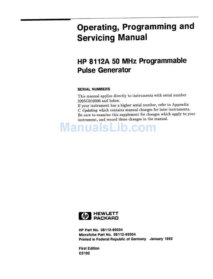
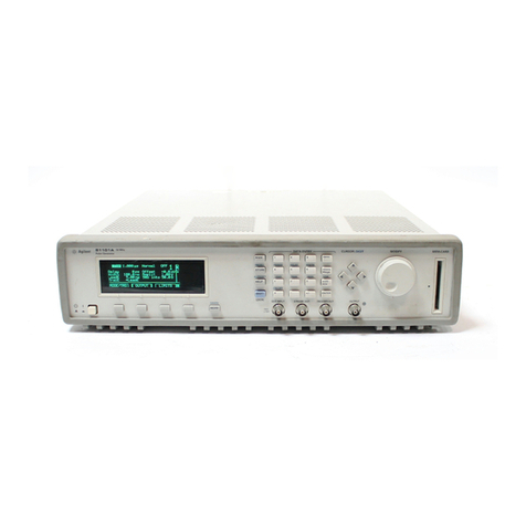
HP 81110A User manual

HP 81110A 165/330 MHz,
HP 81104A 80 MHz
Pulse/Pattern Generators
+
Quick Start
Guide

Front Panel Display and Softkeys

Quick Start Guide
HP 81110A 165/330 MHz,
HP 81104A 80 MHz
Pulse/Pattern Generators
HP Part No. 81110-91010
Printed in Germany June 1998
Edition 1.0, E0698

6 NOTICE HP 81110/04A Quick Start
NOTICE
NOTICE
Copyright
1998 Hewlett-Packard GmbH.
Herrenberger Str. 110-140
71034 Boeblingen
Federal Republic of Germany
All Rights Reserved. Reproduction, adaptation or translation without
prior written permission is prohibited, except as allowed under the copy-
right laws.
Warranty
This Hewlett-Packard product has a warranty against defects in material
and workmanship for a period of one year from date of shipment.During
the warranty period, Hewlett-Packard Company will, at its option, either
repair or replace products that prove to be defective. For warranty ser-
vice or repair,this product must be returned to a service facility desig-
nated by Hewlett-Packard. The Buyer shall pay Hewlett-Packard’s
round-trip travel expenses. For products returned to Hewlett-Packard for
warranty service, the Buyer shall prepay shipping charges to Hewlett-
Packard and Hewlett-Packard shall pay shipping charges to return the
product to the Buyer. However, the Buyer shall pay all shipping charges,
duties and taxes for products returned to Hewlett-Packard from another
country. Hewlett-Packard warrants that its software and firmware desig-
nated by Hewlett-Packard for use with an instrument will execute its
programming instructions when properly installed on that instrument.
Hewlett-Packard does not warrant that the operation of the instrument
software, or firmware, will be uninterrupted or error free.
Limitation of Warranty
The foregoing warranty shall not apply to defects resulting from
improper or inadequate maintenance by the Buyer, Buyer-supplied soft-
ware or interfacing,unauthorized modification or misuse, operation out-
HP 81110/04A Quick Start NOTICE 7
NOTICE
side of the environmental specifications for the product, or improper site
preparation or maintenance.
No other warranty is expressed or implied. Hewlett-Packard specifically
disclaims the implied warranties of merchantability and fitness for a par-
ticular purpose.
Exclusive Remedies
The remedies supplied are the Buyer’s sole and exclusive remedies.
Hewlett-Packard shall not be liable for any direct, indirect, special, inci-
dental, orconsequential damages, whether based on contract, tort or any
other legal theory.
Assistance
Product maintenance agreements and other customer assistance agree-
ments are available for Hewlett-Packard products. For any assistance,
contact your nearest Hewlett-Packard Sales Office.
Certification
Hewlett-Packard Company certifies that this product met its published
specifications at the time of shipment. Hewlett-Packard further certifies
that its calibration measurements are traceable to the United States Insti-
tute of Standards and Technology, to the extent allowed by the Institute’s
calibrating facility, and to the calibration facilities of other International
Standards Organization members.

8 About this book HP 81110/04A Quick Start
About this book
About this book
This quick start guide helps you to quickly install the instrument, to get
familiar with the features, the user interface and give the set up informa-
tion for some real-world signal examples which can easily be used by
varying only some parameter values.
The information is valid for HP 81104A and HP 81110A. Where
required the differences are explicitly mentioned. Possible configura-
tions are:
Output Module for HP 81104A Mainframe:
Output Modules for HP 81110A Mainframe:
As standard the instruments are equipped with one output channel, so,
some of the described features will not be available.
Module Description Max Quantity
HP 81105A 10V/ max.80 MHz Output Channel 2
Module Description Max Quantity
HP 81111A 10V/ max. 165 MHz Output Channel 2
Module Description Max Quantity
HP 81112A 3.8V/ max. 330 MHz Output Channel 2

HP 81110/04A Quick Start About this book 9
About this book
Installing Installing the instrument. Setting Line voltage, replacing fuse and other
installation information.
Introduction An overview of the instrument features, the user interface, and the fun-
damental pulse parameters.
Getting Started
A set of examples designed to demonstrate how to quickly set up a
signal.
User Interface Insight
Please refer to the Reference Guide, p/n 81110-91011.
Programming Reference
Please refer to the Reference Guide, p/n 81110-91011.
Specifications Please refer to the Reference Guide, p/n 81110-91011.

10 About this book HP 81110/04A Quick Start
About this book

HP 81110/04A Quick Start Table of Contents 11
Table of Contents
Table of Contents
NOTICE ...................................................................................................... 6
About this book ........................................................................................... 8
Output Module for HP 81104A Mainframe: ................................................ 8
Output Modules for HP 81110A Mainframe: .............................................. 8
Table of Contents ..................................................................................... 11
Chapter 1 Installation & Safety Requirements
Initial Inspection ....................................................................................... 16
Standard Deliverables: ............................................................................... 17
Options and Accessories: ........................................................................... 18
Options........................................................................................................ 18
Handle Accessory........................................................................................ 19
Rack Mounting Accessories........................................................................ 19
Power Requirements ................................................................................ 20
Replacing the Fuse...................................................................................... 21
Power Cable ............................................................................................. 22
Ventilation Requirements ........................................................................ 23
Thermal Protection ..................................................................................... 23
Overheating Detection................................................................................. 23
Fan Failure................................................................................................... 23
Battery ...................................................................................................... 24
Battery Replacement .................................................................................. 25
Operating Environment ........................................................................... 26

12 Table of Contents HP 81110/04A Quick Start
Table of Contents
Cleaning Recommendation ..................................................................... 27
Acoustic Noise Emission .......................................................................... 28
Acoustic Noise Emission 28
Geräuschemissionswerte 28
Declaration of Conformity ...................................................................... 29
Safety Information ................................................................................... 30
Chapter 2 Introduction
Overview of this Chapter ........................................................................ 34
General Information ................................................................................ 35
Benchtop Testing........................................................................................ 35
Automated Testing...................................................................................... 35
Upgrade Capability..................................................................................... 36
User Interface Concept ............................................................................ 37
The Display ................................................................................................ 37
The Controls .............................................................................................. 38
Numerical Data Entry ................................................................................ 38
Parameter Selection and Modification ....................................................... 38
Quick Access of Menus and Parameters ................................................ 40
Additional Functions .................................................................................. 40
Select Step Size .......................................................................................... 40
Overprogramming ...................................................................................... 41
Display Modes ........................................................................................... 41
Screen Menus ............................................................................................. 42

HP 81110/04A Quick Start Table of Contents 13
Table of Contents
Special Function Keys .............................................................................. 43
Shift/Local Function Key ........................................................................... 43
Help Function Key ..................................................................................... 43
Store/Recall Function Key ......................................................................... 43
Default Setting............................................................................................. 44
Manual Trigger Function Key .................................................................... 44
Screens Overview ..................................................................................... 45
Available Operating/Trigger Modes ....................................................... 47
Trigger and Strobe Output........................................................................... 48
Setting Timing Parameter Formats and Values .................................... 49
Setting Level Parameter Formats and Values ....................................... 51
Internal Error Check.................................................................................... 52
Editing Pattern ......................................................................................... 54
Setting Limits ............................................................................................ 57
Thresholds and Trigger-Levels ............................................................... 59
Reading/Storing on Memory Card ......................................................... 60
Changing Configuration .......................................................................... 62
Output/Output 1 and Output 2 Parameter Grouping .......................... 64
An Overview of the Front and Rear Panel ............................................ 66
Inputs and Outputs ..................................................................................... 67
Chapter 3 Getting Started
Introduction .............................................................................................. 70
Manual Example Signals ............................................................................ 70

14 Table of Contents HP 81110/04A Quick Start
Table of Contents
Generic Signals........................................................................................... 70
Advanced Signals ....................................................................................... 70
Programming Examples ............................................................................. 70
Documentation Conventions: .................................................................... 71
Examples ................................................................................................... 72
1. Setting up a Clock Signal ....................................................................... 72
Device Command List for the Clock Signal .............................................. 77
2. Setting up a Pulse Signal ....................................................................... 79
Device Command List for the Pulse Signal ............................................... 84
3. Setting Up a Serial Data Stream Signal ................................................. 86
Device Command List for the Data Stream Signal .................................... 89
4. Setting Up an Edge-displacement Signal ............................................... 91
Device Command List for the Edge-displacement Signal ......................... 95
5. Setting Up a Dual Clock Signals ........................................................... 97
Device Command List for the Dual Clock Signal ................................... 101
6. Setting Up a Burst Signal ..................................................................... 103
Device Command List for the Burst Signal ............................................. 107
Index ........................................................................................................ 109

HP 81110/04A User’s Guide Installation & Safety Requirements 15
Chapter 1
1Installation &
Safety Requirements

16 Installation & Safety Requirements HP 81110/04A User’s Guide
Installation & Safety Requirements
Initial Inspection
Initial Inspection
Inspectthe shipping container for damage. If the container or cushioning
material is damaged, keep it until the contents of the shipment have been
checked for completeness and the instrument has been verified both
mechanically and electrically.
WARNING: To avoid hazardous electric shock, do not perform electrical
tests when there are signs of shipping damage to any part of
the instrument’s outer covers or panels.
If the contents are incomplete, or there is mechanical damage, or if the
instrumentdoes not work as expected within its specifications, notify the
nearest Hewlett-Packard office. (please request the latest performance
tests from Hewlett Packard) Keep the shipping materials for inspection
by the carrier. The HP office will arrange for repair or replacement with-
out awaiting settlement.

HP 81110/04A User’s Guide Installation & Safety Requirements 17
Installation & Safety Requirements
Initial Inspection
Standard Deliverables:
1The instrument, either an HP 81110A or an HP 81104A Mainframe
with one or two channels installed.
2This Quick Start Guide and a Reference Guide
3A power cord.
Figure 1 The Standard Deliverables
(LWKHU+3$RU+3$
7KLV4XLFN6WDUW*XLGH
$3RZHU&RUG
7KLV)LJXUHVKRZVDQ+3$
DQGWKH5HIHUHQFH*XLGH

18 Installation & Safety Requirements HP 81110/04A User’s Guide
Installation & Safety Requirements
Initial Inspection
Options and Accessories:
Options
Rear Panel Connectors Option UN2
All inputs and outputs are at the rear
panel.
Second Channel HP 81105A 10V/80 MHz for
mainframe HP 81104A
HP 81111A 10V/165 MHz or
HP 81112A 3.8V/330 MHz for
mainframe HP 81110A
1 MB SRAM Memory Card Option UFH
(HP part numer 0950-3880)
Figure 2 Standard Instrument’s Rear Panel
Figure 3 Rear Panel Connectors when Option UN2 is installed

HP 81110/04A User’s Guide Installation & Safety Requirements 19
Installation & Safety Requirements
Initial Inspection
Handle Accessory
Front Handle Kit HP part number 5063-9226
Rack Mounting Accessories
Rack Mount Kit HP part number 5063-9212
Rack Mount and Front Handle Kit HP part number 5063-9219
Rack Slide Kit HP part number 1494-0059

HP 81110/04A User’s Guide Installation & Safety Requirements 20
Installation & Safety Requirements
Power Requirements
Power Requirements
CAUTION: BEFORE APPLYING AC LINE POWER TO THE
INSTRUMENT, ensure that the correct line fuse is installed in the
fuse holder and the correct power cable is fitted.
NOTE: When the front panel switch is off, the Mainframe is in ’Standby’
mode. Disconnection from the AC Line Power is accomplished
only by disconnecting the power cord. Please make sure that the
power cord is easily identifiable and can quickly be reached by the
operator.
The following symbol is close to the ‘Standby’ switch on the front panel
of the instrument.
Figure 4 The ‘Standby’ Switch Symbol
The instrument can operate from any single-phase AC power source
supplying 100 - 240 V in the frequency range from 50 to 60 Hz, or 100 -
120 V at 400 Hz. The maximum power consumption is 300 VA with all
options installed. When the instrument is switched on the power supply
adapts automatically to the applied AC power (Auto Selection) and
monitors the AC power range during operation.
Table 1 Line Fuse
Line Voltage Fuse Type HP Part
Number
100 - 240 V~ T 10A, 250 V 2110-0720

HP 81110/04A User’s Guide Installation & Safety Requirements 21
Installation & Safety Requirements
Power Requirements
Replacing the Fuse
1Remove the power cord.
2Unscrew the fuse-cap at the rear of the instrument beside the power-
inlet socket.
Figure 5 Fuse Holder at Rear Panel
3Replace the fuse with the equivalent part (see Table 1 on page 20).
4Refit the fuse-cap.
Fuse Holder and
Fuse Cap

22 Installation & Safety Requirements HP 81110/04A User’s Guide
Installation & Safety Requirements
Power Cable
Power Cable
In accordance with international safety standards, this instrument is
equipped with a three-wire power cable, see Figure 6 on page 22 for the
part numbers of the power cables available. When connected to an
appropriate AC power receptacle, this cable grounds the instrument cab-
inet.
WARNING: To avoid the possibility of injury or death, the precautionary
Warnings given on the inside front-cover of the manual must
be followed before the instrument is switched on.
Figure 6 Power Cables - Plug Identification
This manual suits for next models
1
Table of contents
Other HP Pulse Generator manuals