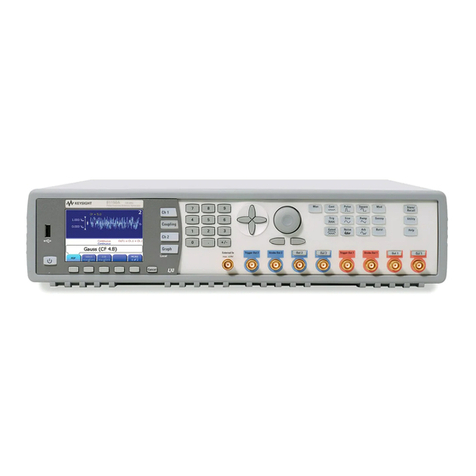
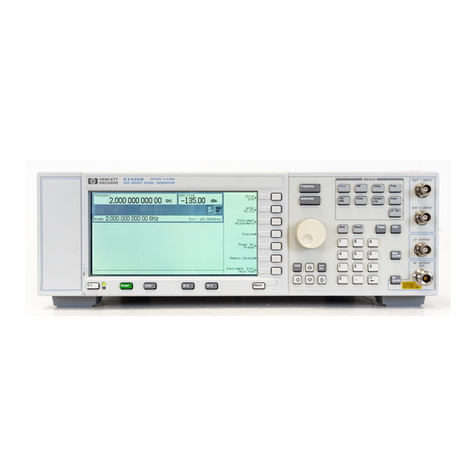
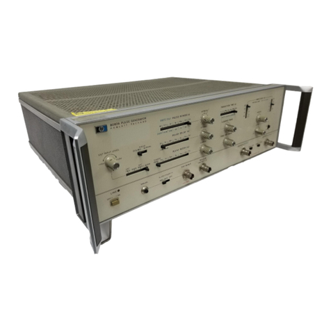
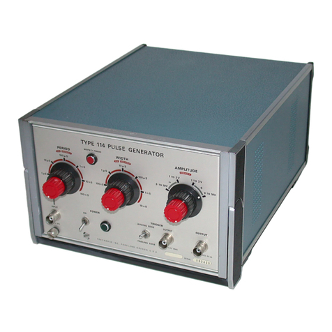
HP 8082a Service manual


CERTIFICATION
The Hewlett-Packard Company certifies that this instrument was thoroughly
tested and inspected and found to meet its published specifications when
shipped from the factory. The Hewlett-Packard Company further certifies
that its calibration measurements are traceable to the US National Bureau of
Standards to theextentallowed by the Bureau’scalibration facilities or to the
calibration facilities of other International Standards Organization Members.
WARRANTY AND ASSISTANCE
XII
Hewlett-Packard products are warranted against defects in materials and
workmanship. This warranty applies for one year from the date of delivery,
or, in the case of certain major components listed in the operating manual,
for the specified period. We will repair or replace products which prove to be
defective during the warranty period. No other warranty is expressed or
implied. We are not liable for consequential damages.
For any assistance contact your nearest Hewlett-Packard Sales and Service
Office. Addresses are provided at the back of this manual.
PREFACE
Qne copy of this manual is supplied with each instrument. Additional copies
may be purchased from
the
locai
Hewlett-Packard Sales and Service Office.
Specify the instrument model number and serial number. A microfiche
version of this manual is availabie under part number 08082-90502
Reference should be made to the manual change
sheeis
supplied with the
manual for errata and technical changes, and
Po
Section 7 (Backdating/
Updating)
~
Technica!
changes are indicated by the prefix (the first five characters) of the
serial number which appears on the rear panel of the instrument; the serial
number prefix of the instrument to which this manual applies directly is:

COMTENTS
Section 1General information
l-1
introduction
................................................. l-l
f-7
EClOlitput
.................................................
l-4
Section 2Installation
2-7
2-1
2-2
2-4
2-6
2-8
2-9
2-12
2-15
2-17
2-19
2-26
2-22
General
..................................................... 2-l
initial Inspection
......................................... 2-l
Accessories
........................................... 2-1
PowerCords
........................................... 2-l
installation
................................................... 2-l
PowerCord
........................................... 2-1
Power Source Requirements
................................. 2-2
Temperature Requirements
................................. 2-2
Rack Mounting
............................................... 2-2
Claims and Repackaging
......................................... 2-3
Claims for Damage
....................................... 2-3
Repackaging for Shipment and Storage
......................... 2-3
Section 3Operating Instructions
3-1
General
..................................................... 3-l
3-4
Externat input Characteristics
..................................... 3-l
3-8
Square Wave Operation.
.......................................... 3-2
3-10
Output Amplitude Controls
....................................... 3-2
3-15
incompatible Control Settings
..................................... 3-2
3-17
NormOperatingMode
........................................... 3-2
3-20
EXTwidthOperatingMode
....................................... 3-3
3-22
Gate Operating Mode
........................................... 3-4
3-24
EXT Trig. Operating Mode
....................................... 3-4
3-26
Apptications Notes
............................................. 3-5
Section 4 Theory of Operation
4-l
4-8
4-21
4-28
4-36
4-38
4-44
44%
4-4%
4-50
introduction
................................................. 4-l
Repetition Rate Generator
.......................................
4-1
Delay and width Generators
....................................... 4-3
Slope Generator
............................................... 4-5
Buffer Amplifier
...............................................
4-6
Output Amplifier and Vernier Attenuators
.............................
4-6
DC offset for Positive
Pulse
Outputs
................................. 4-7
Step Attenuator
............................................... 4-7
~xter~a]DC~f~~
.............................................
4-7
Power Supplies
...............................................
4-7

List of Contents
CXXUTEMTS
Section 5Maintenance
5-l
5-4
5-4
5-7
5-9
5-12
5-15
5-21
5-24
5-28
5-32
5-39
5-41
5-45
5-46
5-46
General
..............................
.5-l
Removal of Covers
...........................
5--f
Removal of Assemblies
..........................
5-l
General
..........................
.5-l
Power Supply Board
-
Assembly 2
................
.5--l
Repetition Rate Generator Board
-
Assembly 3
............
5-l
Output Amplifier Board
-
Assembly 4
...............
5-l
Buffer Amplifier Board
-
Assembly
8
..............
.5-
1
Output Ampiifier Board
(A41
-
Hybrid Circuit Renewal ........
5-l
OffsetBoard-Assembly5 ................... .5-2
Mother Board
-
Assembly 1
....................5-2
Performance Checks
.........................
.5-2
Internal Checks and Adjustments
............................
5-17
Troubleshooting using the 15265 A Test Box
..................... 5-17
Safety Check
......................................
5-17
Tmubleshootiq
Tips .................................. 6-l
7
Section 6Diagrams and Replaceable Parts
6-1
6-3
6-4
h?troduction
............................
.6-l
Ordering information
........................
.6--l
General
..........................
.6-d
Sction
7
7-l
7-3
7-5
7-7
Backdating
Serial Numbers
1419G96145
And Below
.......................... 7-l
Serial Numbers
14fOG99270
And Below
..........................
7-l
9erial
Numbers
t419G66271
to 1410669390 ......................
7-1
Serial Numbers
1416G66391
And Above
..........................
7-1
Page

Figure
2-a
2-2
2-3
2-4
2-5
3-1
3-2
3-3
3-5
3-6
3-7
3-8
3-9
3-10
3-11
4-1
4-2
4-3
4-4
4-5
4-6
4-7
4-8
4-9
5-l
5-2
6-l
Service Sheets
1
Repetition Rate Generator
-
Board A3
...............................
6-17
2a
Delay and Width Generators
-
Part of Board A4
......................... 6-21
Zb Slopa Generator
-
Part of Board A4 and Buffer Amplifier
-
Soard
A8 ......... 6-23
2c Output Amplifier
-Partof
Board
A4.
................................ 625
3a Slope Generator Current and Voltage Source
-
Part of Board A5
............... 6-27
3b DC Offset and Amplitude Vernier
-
Part of Board A5 ................... 6-29
4Step Attenuator
-
Board A9 .....................................
6-31
5
Power Supplies
-
Board A2
....................................... 6-33
Title
~.
8[182A
and Supplied Accessories
...................................
2-9
Available Accessories
........................................... 2-6
Power Cords
................................................. 2-2
Switch Settings for the Various Nominal Powerline Voltages
................. 2-2
Removing Plastic Trim
........................................... 2-2
Front Panel Controls and Connectors
..............................
3-Q
Effect of External lnput Controls ................................... 3-1
Positioning of Controls
......................................... 3-2
Pulse Output in NORM Mode ..................................... 3-3
Pulse
Dutput
in External Width Mode
............................... 3-3
PulseGutputinGateMode
....................................... 3-4
Pulse Output in External Trigger Mode
............................... 3-4
Stepped pulse with high-2 output
................................... 3-5
Flip-Ffop
Tzsr
Circuit ........................................... 3-6
FlipF!op
Test Waveforms
....................................... 3-6
NoisePulses
................................................. 3-7
6082A
Pulse Generator
-
Block Diagram
............................. 4-Q
Repetition Rate Generator
-
Block Diagram
........................... 4-1
Rate Generator
............................................... 4-2
Transition Detector Pulse Output
................................... 4-3
Delay Generator
-
Block Diagram
................................... 4-4
Slope Generator Diagram and Waveforms
.............................. 4-5
Attenuator Element
........................................... 4-6
Input
z&age
and Attenuator ....................................... 4-7
Attenuator and Gain Control
..................................... 4-8
Connections between Test Box
15265A
and
8Q82A
....................... 5-12
location of adjustment controls
................................... 5-25
Mainframe Parts Identification
..................................... 6-2

List of
Table
TABlS
TabJe
Title
l-1
5-1
5-2
5-3
5-5
5-7
5-9
5-10
5-11
5-l 2
5-13
5-14
5-15
5-16
5-17
5-18
5-19
5-20
5-21
5-22
5-23
5-24
5-25
5-26
5-27
6-l
6-2
6-3
6-4
Specifications
................................................
Test Equipment
z
.
..’
Accessories for Performance Checks
...................
Performance Check
-
Repetition Rate
...............................
Performance Check
-
Delay (Slow)
.................................
Performance Check
-
Width
(Slow)
.................................
Performance Check
-
Jitter
.....................................
Performance Check
-
Width
(Fas;j
.................................
Performance Check
-
Delay (Fast) .................................
Performance Check
-SquareWaveDutyCycle
.........................
Performance Check
-
External Functions .............................
Performance Check
-
Transition Time
...............................
Performance Check
-
Preshoot, Overshoot and Ringing
....................
Performance Check
-
Amplitude
...................................
Performance Check
-
Check Record
.................................
Summary of adjustable and factoryselected components
...................
Test Equipment and Accessories for Internal Checks and Adjustments
.............
TestandAdjustmentsPerformedbyTestBox
15265A
.....................
Power Supply
.................................................
Rep. Rate
...................................................
Delay and Width (Verniers CW)
.....................................
Amplitude, Risetime, Overshoot
(Ins
-
511s
Transition Time)
.................
Amplitude, Risetime, Overshoot (Slower Transition Times)
.................
Pulse Shape and Transition Times
...................................
Positive Pulse Baseline
...........................................
Width
.....................................................
Gate
......................................................
Double Pulse
.................................................
Safety Check
.................................................
Component Designators
..........................................
Manufacturer% Code Numbers end Abbreviations for Parts Lists.
..............
h-ts
List ...................................................
Schematic Diagram Notes
.........................................
l-2
5-3
5-4
5-4
5-5
5-5
5-6
E-7
5-7
5-8
5-9
5-9
5-19
5-l 1
5-18
5-19
5-29
5-23
5-23
5-24
5-25
5-26
5-26
5-27
5-27
5-27
5-27
5-28
6-l
6-l
6-5
6-13

SAFETY
CQMSIDERATlOMS
GENERAL -This is a Safety Class
I
instrument
(provided with terminal for protective earthing)
and has been manufactured and tested according to
international safety standards.
OPERATION
-
BEFORE APPLYING POWER
comply with the instalfation section. Additionally,
the following shall be observed:
Any interruption of the protective (ground-
ding) conductor (inside or outside the
instrument) or disconnecting the protective
earth terminal is likely to make this instru-
ment dangerous. tntentionaf interruption is
prohibited.
Whenever it is likely that the protection has
been impaired, the instrument must be made
inoperative and be secxed against any un-
intended operation.
Make sure that only fuses with the required
rated currznt and of the specified type
{normal blow, time deiay, etc.) are used for
replacement. The use of repaired fuses and the
short-circuiting of fuseholders must be
avoided.
Adjustments described in the manual are per-
formed with power supplied to the instrument
while protective covers are
remowed.
Energy
available at many points may, if contacted,
result in personal injury.
Any adjustment, maintenance, and repair of
the opened instrument under voltage should be
avoided as much as possible, and when inevitable,
should be carried out only by a skilled person
*who is aware of the hazard involved.
SAFETY
SYMBl)LS
The apparatus will be marked with this
symbol when it is necessary for the user to
refer to the instruction manual in order to
protect the apparatus against damage.
Indicates dangerous voltages.
Earth terminal {sometimes used in man-
ualto indicated circuit common con-
nected to grounded chassis).
WARNING
The WARNING sign denotes a
hazard. It calls attention to a
procedure, practice or the like, which,
if not correctly performed or adhered
to, could result in injury or loss of tife.
Do not proceed beyond a WARNING
sign until the indicated conditions
are fully understood and met.
CAUTION
The
CAUTiON
sign denotes a hazard.
It calls
atkct:!ttion
to an operating
procedure, practice, or the like, which,
if not correctly performed or adhered
to, could result in damage to or destruc-
tion of part or all of the equipment.
Do not proceed beyond a CAUTION
sign until the indicated conditions are
fully understood and met.
Capacitors inside the instrument may still be
charged even if the instrument has been :liscon-
netted from its source of supply.

GENERAL INFORMATION
t-1
INTRODUCTliON
1-2 The
8082A
is a 250 MHz
dual
channel pulse
source with variable leading and trailing edge transition
times as fast as Ins. It also has variable pulse frequency,
delay, width, offset and amplitude. The normal/compie-
ment reiationship and the polarity of either output can
be reversed. Single pulse, double pulse and square wave
operatiol) are available. There are also four trigger
modes-
1-3
Norma!
Mode. in this mode the
8082A
oper-
ates as a self-contained pulse source with
f&i
control
of the
p&e
parameters from the front panel controls.
1-4
Ext
Trig Mode. in this mode the pulse and
trigger output frequencies are determined by the fre-
quency of an externaity applied signal. The other puke
parameters are varied from the front panei controis.
l-5
Gate Mode. In this mode a gating signal
enables the pulse and trigger outputs.
1-6
External Width Mode. in this mode the pulse
frequency and width are determined by the frequency
and width of an externally applied signal. The delay be
tween input and output is fixed. The trigger output
is the shaped trigger input signal.
1-7
ECL OUTPUT
1-8
The
8082A
has an ECL position on each of
its amplitude range switches. When e;ther or both of
the switches are se? to this position, both
8082A
outputs
automatically deliver a fixed voltage swing of
-0.9V
to
-7.7V
typical (into an open circuit) for driving ECL
logic.

Table l-7 Specifications
These specifications apply when:
PULSE
CHARACTERlSTlCS
Bource and
Doad
impedance 5052)
Transition Times:<
Ins
to
0.5ms
in
6
ranges. First range from
<
Ins to
5ns controls ieadingand trailing edges
simuitaneoufsy. For all other ranges
transition timesvariable independent-
ly up to
7:lO.
Difference between risetime and fall-
time is less than 25% of the faster
transition time of the two.
Overshoot and Ringing:
&
+
5% of
pulse ampiitude may increase to
3~
10%
with amplitude vernier CCW.
Preshoot:
<
+
5% of pulse amplitude.
Linearity: Linearity aberration for
both slopes
<
5%
FOF
transition times
> 5ns.
Output: Maximum amplitude is 5V
from
5051
into
5OQ.
Maximum out-
put
voltage
is
+
5V
(amplitude t off-
set).
Offset
>
Z!T
2V,
into
5OG!
Baseline: OV
t
150mV
with offset
switched off and amplitude range
set to maximum. Other amplitude
ranges reduce baselineproportionately
DCSource
Impedance:
5052
T
5% .
Reflection Coefficient
Reffection
1s
2% typical for steps with
1
ns rise time
applied to output connector on all
amplitude ranges except
5V
range.
On the 5V range, the reflection may
be 15%.
OutPut
protection: Cannot be da-
maged by open
o;
short circuits or
application of ext
<
It
6
volts or
+
2QOmA
independent of control set
-
tings.
Attenuator: Two separate three step-
attenuators reduce the outputs to 4
V.
Vernier is common for both outputs
and reduces the output to
0.4V
minimum. A further position
pro-
vldesECL-compatibleoutputsi-O,9V
1)
both outputs are
terminated by a
50-Q
load,
TIMING
Repetition Rate: > 250
hri!-!z
to
<
1
kHz
in 6 ranges.
Period Jitter:
<
0.7 % + 50~s
Delay: <
2ns
to >
0.5ms
in 6 ranges
plus typ. 18ns fxd. with respect to
trigger output.
Delay Jitter:< 0.1%
9
50~s
Double Pulse: Up to 125 MHz max.
(simufatesEXIMHz).Min pulsespacing
2
4ns.
Delay
Duty Cycle:
>
50%
Pulse Width:
<
&s
to
>
0.5ms
in 6
ranges.
Width Jitter: < 0.1%
+
50~s
Width Duty
Cycte:
> 50%
Square Wave: A further position of
the Pulse Width switch provides
Square Wave output. (Delay and
double pulse are disabled, max. Rep.
Rate 250 MHz). Duty cycle is 50%
+
10% up to 100 MHz, 50%
+
15%
for
>
100 MHz.
Trigger Output: Negative going
Square Wave
(50Y3
duty cycle typ.)
>
500mV from
50R
Into
5Os1.
Internal
5Ofi
ioad can be switched
off by slide-switch on PC-board.
Amplitude increases to
2
1V
into
5Cfz
up to 200 MHz.
Trigger Output Protection: Cannot
be damaged by short circuit or appli-
cation of
externai
f
200mA.
EXTERNALLY CONTROLLED
OPERATION
External
input
1
npus
Impedance:
5Ofi
+
10%.
DC
coupled.
Maximum input:
f
6V
Trigger Level: Adjustable
-
1.5V to
2) the internal
5042
source impedance is
selected.
Slope Control: Positive, negative or
manual selectable. In the MAN-posit-
ion all ext. functions can be con-
trolled by push button.
Button
pushed in simulates an “on-signal”.
Sensitivity: Sine-wave >
2OOmVpp,
pulses
>
2QOmV.
Repetition Rate: 0 to > 250 MHz.
Ext.-Controlled Modes
Ext.frigger:
There are approximateiy
7ns delay between the external rnput
and the trigger output. Rep.-Rate is
ext. controlled (is triggered by exter-
nal signal). Trigger output provides
the pulse-shaped input signal. Square
wave mode is disabled.
Synchronous Gating: Gating signal
turns rep. rate generator on. Last
pulse is of normal width even if gate
ends during the pulse.
External Width: Output pulse width
determined by width of drive input.
Rep. Rate and Delay are disabled.
T
J
igger output provides shaped input
siqnal.
OPTIONS
Option 907 Front Handle Kit
Option 908 Rack Flange Kit
Option 909
Rack Fiange plus Front
Handie
Kit
Option 910
Additional Instrument
Manual
GENERAL
Power Requirements: 7 OOV
I
12QV,
22OV
*
24ov
t+5%,
-
10%)
48
-
440
Hz. Powt:r consumption
85VA
max .
Weight:
Nei
7.9 kg
417.44
lhs),
shipping 8.9 kg 119.63 Ibsf.
Dimensions
426mm
wide,
f45m:m
hi&
li8nmm
drwn
i
IG
Y/A
;nc
v

Figure
2-I.
8082A and Supplied Accessories
Front handle
Order Option
907
Figure 2-2. Avaiiable Accessaries
Rack flange with front handle
Order Option 909 Rack flange
Order Option 908

t
2-I
GENERAL
2-2 Initial
I
nspction
2-3
Inspect the instrument and accessories for
physical damage, and if damage is evident, refer to para-
graph 2-19 for the recommended claim procedure and
repacking information.
2-4
ACCf?SXHkS
2-5
The following accessories are strpptied with
the standard instrument (Figure
2-
1)
:
1
A fuse
(for
22Clf240V
operation)
2A
fuse (for
7
lWf20V
operation)
Power cord
Operating and Service Manual
HP Part Number
2
110-0007
211 o-0202
see Figure 2-3
For an additional manual. order option 910.
Handles are rack mounting flanges are delivered with
the
instrument only if the appropriate option (Figure 2-2)
is ordered
NEMA
TYPE
HP
Part No. 8120-l
348
I
i
LINE
=
BLACK
NEUTRAL = WHITE
I
GRGUNO
=YfLLaNiGAEEN
1
SCHUKO
TYPE
HP Part No.
8120-
1689
LINE = BROWN
NEUTRAL = BLUE
GROUND
=
YELLOW/GREEN
2-6
PowerCords
2-7
The instrument~is :;upplied with one of the
power cords shown in Figure 2--3.
2-8 INSTALLATION
2-9
PowerCord
2-10
The
3wire
power cable supplied with the
801 GA, when connected to the appropriate
pozver
out-
let, grounds the instrument cabinet and paneis.
Tc
ore
serve this safety feature when operating the instrumer,?
‘ram an outlet without a ground connection, use an
appropriate adapter and connect the ground lead
(green/yellow1 to an external ground.
2-l
1
If
the plug on the cable does not fit your
power outlet, then Cut the cable at the plug end and
connect a suitable plug The plug should meet local
safety requirement and include the following features:
a. Minimum current rating of 2A
b.
Ground connection
c. Cable clamp
The colour coding used in the cable will depend on
the
cable supplied (see Figure
2-Z?.
I
BRITISH STANDARD TYPE
HP Part No. 8720-1351
LINE =
BROWPd
NEUTRAL = BLUE
GROUND
=
YELLOW/GREEN
USED
IN
;4USTRACIA
r-
HP Pan
!JO.
8120-7369
LINE = BROWN
MEUTRAL
=
BLUE
GROUND =
YELLOW/GREEN

WARNING
t
To avoid the possibility of injury or death, the
foliowing
precautions must be foffowed before the instrument is
switche;l
on:
a if this instrument is to be energized via an auto-
cransformer for voltage reduction, make sure that the
ground connection is not interrupted.
b. The power cable plug shaff only be inserted into a
socket outlet provided with a protective earth contact
The protective action must not be negated by the use
of an extension cord without a protective conductor
&oundingL
c
The safety check (Table
5-27)
shall be executed
before connecting the instrument to the supply.
2-13
The instrument will operate from nominaf
ac
line
5dq3plies
of
WOV,
12OV,
22W
or 240V
(-lo%,
+
5%)
at 48
Hz
to 66
Hz
Two switches on the rear panel
allow one of the
four
voltages to be selected.
1oov
12OV
22ov
24w
Figure
Z-4.
Switch Settings for the various Norminal
Powerline
Voftages
*
Before applying power to the instrument,
check on the rear panel that the switch is
set in accordance with bcal supply condi-
tions
2--i4
follows: To check the power requirements proceed as
a Remove
tk
fuse and check its value:
for
22OV/24OV
operation 1 A
for
lOOV/l2OV
option
2P
b.
Check that the iine sefector switch
positions corresponds to the local suppEy
voltage.
If
they do not correspond use a
screwdriver to change the switch positions.
c.
insert the correct fuse into
tha
fus&@&r.
d. Connect the power
r&e
to the rear con-
nector.
2-15
TemperatureRequirements
2-16
The instrument operates within specifi-
cations when the ambient temperature is between BoC
432’F)
and .50°C (122OF1. The word generator may be
stored between
-4O’C
(-40°F)
and
75’
(167OF).
2-18
Figure 2-2 shows the possible handlelracrc-
mounting configurations. If handles are fitted and
s&se
quentfy need to be removed, the plastic trim
must
first
be taken off as shown in Figure
2-5.
Lift
a
corner
of the pla5tk trim with a
screw-
give
a sharp tap in the direction of

2-19
S AMS)REPACKAGING
2-m
ClaimsforDamage
Z-21
If ;rhysical damage is evident or if the instru-
ment does not meet specification when received, notify
the carrier and the nearest Hewlett-Packard
blesfervice
Office. The Sates/Service Office wilt arrange for repair or
replacement of the unit without waiting
for
settlement
of the claim against the carrier.
2-23
If
the instrument is to be shipped to a Hew
lett-Packard SeWService Office, attach a tag showing
owner, address, model and serial number, and the repair
required The sriginel shipping carton and packaging
material may be reuseble but the Hewlett-Packard
Sales/Service Office
wilD
also provide information
ancl
mcommendations on materials to be used if the original
pecking is not
awaitabie
or reusable.

1
RATE switch: for selecting the
ranga
of the
pulse
rate.
2
Rate VERNIER: for continuous adjustment of the repetition
rate within the range selected on the RATE switch. Clockwise rotation
increases the
pulse
period
(redwoq
the fate).
3PULSE DOUBLE/NORMAL switch: in the DOUBLE PULSE
position the
BCtB2A
delivers two
pulses
for every
tr@ger
pulse
-
one
pulse in
pha+with
the trigger owtpwt and one delayed by the amount
set
on the PULSE DELAY controls. DOUBLE PULSE is not available
in the EXT WIDTH mode and is automatically
inhib@d
if selected.
In the NORMAL position, for each trigger pwlse, the
8DB2A
delivers
one
pwtse
which is delayed on the trigger pulse by the amount set on
the PULSE DELAY
controfs.
4PULSE DELAY switch: for selecting the range of the pulse de-
lay with respect to the
tr&er
output
in NORM, GATE and EXT
TRIG modes. Has no effect in the EXT
WfDTH
and SQUARE WAVE
mndes.
5Pulse dday VERNIER: for continuous adjustment of the pulse
delay within the range selected on the PULSE DELAY switch.
Clock-
Wise rotation increases the delay.
6EXT INPUT LEVEL control: defines the
threshold
level of the
EXTERNAL INPUT over a range
-1.5V
to
+1.5V
_
7Mode switch: selects either the internal (NORM) mode or one of
three external modes
(EXT
WIDTH, GATE or EXT TRIG).
8PULSE WIDTH switch: selects the range of the pulse width re-
quired in all modes except EXT WIDTH. When
SQUARE
WAVE is
selected
a square wave output of 59% duty cycle is
prodweed.
The
frequency of the square wave depends on the PULSE
PERIOD
setting.
9Pulse width VERNIER: for continwows adjustment of the pulse
width within the range set on the PULSE WIDTH switch.
70
TRANSITION TIME switch: for selecting the range of leading
and trailing edge transition times.
11
LEADING EDGE vernier: for continuous adjustment of the
leading edge transition time within the range selected on the TRANSI-
TION
TlNlE
switch. On
the
fastest range this vernier controls both
leading and trailing edges.
92
TRAlllNG
EDGE vernier: for continuous adjustment of the
trailing
edga
transition time within the range selected on the TRAN-
SITION
TfME
stitch.
13
AMPLITUDE switch: for selecting
tha
range of the output
pulse
amplitwde
available at the OUTPUT
/
OUTPUT
connactor.
tn
the
ECL position the OUTPUT
/
OUTPUT
oonnector
delivers
pulses
of
fixed
ampfitwde
(-0.9V
to
-1.7V
into an open circuit) and the ampli-
tude vernier and the offset control are disabled.
14
AMPLITUDE switch: for
selecti*rg
range of the output
pulse
amplitude available at the OUTPUT
/
OUTPUT connector.
In
the
ECL position the OUTPUT
/
OUTPUT connector delivers pulses of
fixed amplitude
(-CL9V
to
-1.7V
into an open circuit) and the
amPh-
twde vernier and the offset control are disabled.
15
Amplitude VERNIER: for continuous adjustment of
pulse
am-
plitude from both pwlse outputs simultaneowsfy within the ranges
set on the AMPLITUDE switches.
16
OFFSET vernier: for adjustment of the
baseline
of both
output
pulses simultaneously over the
range
-2V to
*2V.
17
OFFSET switch: for enabling/disabling the OFFSET vernier.
In the OFF position the baseline of both outputs is
zero
wafts.
18
OUTPUT
I
OUTPUT connector:
8NC
connector.
19
NORM
/
COMPL switch: reverses the dwty cycle of the two
outputs, what was the normal
output
becomes the complement and
vice versa.
29
NEG/POS
switch: determines the polarity of both output pulses.
21
OUTPUT
/
OUTPUT connector: BNC connector.
22
TRIGGER OUTPUT
I-)
connector:
ENC
connecto:, supplies
negative square wave at a rate determined by the setting
gf
the pulse
period controls.
Pulse
delay is
refered
to the negative going edge of
the trigger. In EXT TRIG and EXT WIDTH modes it will deliver a
shaped version of the trigger input. In GATE mode it will deliver
pulses at the rata set on the pulse period controls for as long as the
gate is open.
23
EXT INPUT connector:
ENC
connector to which trigger pulses
are
epplied
in the EXT
TRtG,
GATE and EXT WIDTH modes.
24
SLOPE
/
POLARITY switch determines whether a rising
(POS)
or falling
(NEG)
signal will trigger or gate the external
input
on.
MAN
position means that the external signal can be simulated by pressing
the MANUAL button.
25
MANUAL button provides a means of initiating a
single
pulse
(EXT
TRIG
mode)
each time the button is pressed, a train of
pulses
(GATE
mode) While the
button
is pressed, or a
pulse
Whose width
is
WJd
to the time the button is pressed (EXT
WIDTH
mode).
28
LINE
ON/OFF switch: press-for-on, press-for-off
switch.
27
LINE lamp: glows when LINE ON/OFF
switch
is ON.

REAR PANEL
36 Fuse
30
Linevoltagesektor
See
Section2
32 Line connector
INTERNAL
(See
Figure
6-2)
A331
Trigger output
!K&!
internalloadon/off.

OPEF?ATlNG
INS
3-I
GENERAL
3-2
This section is divided into two parts. The
first part gives
scrme
general notes on the operation of
the SO82A together with operating instructions for each
of the four operating modes:
NORM operating mode
EXT
WfDTH
operating mode
GATE operating mode
EXT
TRiG
operating mode
Full setting-up instructions are given for Normal mode
3-5 The SLOPE/POLARITY switch
determines
followed by any changes in control settings required for whether a rising (POS) or falling (MEG) signal will trigger
the other three modes. Stylized waveforms are given for or gate the external input on. Figure 3-2 shows the effects
each mode to show the resultant pulse shapes. For ease of these controls in the External Width mode.
of operation the instructions will refer to Figure
3-1
which shows the controls identified by a reference num-
ber in a circle. The same reference numbers are used in
the text when each control is mentioned.
3-3
The second part of this section gives appli-
cations information.
3-4 EXTERNAL
lNPUT
CHARACTERISTICS

3-6
Any external input pulses must have an ampli-
tude of at least 2OOmV peak-to-peak and must be at least
2ns wide at the level at which
triggering is to occur.
3-7 If the SLOPE/POLARITY switch is set to
MAN, the external signal can be simulated by pressing
the MANUAL pushbutton. This button provides a means
of initiating a single pulse (EXT TRIG mode) each time
the button is pressed, a train of pulses (GATE mode)
while the button is pressed, or a pulse whose width is equal
to the time the button is pressed
(EXT
WIDTH mode).
34
SQUARE WAVE OPERATION
3-9
There is a 8quare Wave facility on the 8082A
which produces a square wave output of 50% duty cycle
in NORMAL mode. If Square Wave is selected in Exter-
nal Trigger or External Width modes, the output is a pulse
shaped version of the trigger input (the output waveforms
are the same as for External Width mode, see Figure
3-4).
If Square Wave is selected in Gate mode, the output is a
gated square wave, the repetition rate of which is set up
on the pulse period controls.
3-10
OUTPUT AMPLITUDE CONTROLS
3-11
Vernier
3-12
Because the amplitude vernier is common to
both outputs, the amplitude relationship of one output
totheotheris1:1,7:2or1:5
3-13
ECL Outputs
3-14
To obtain normal and complement ECL com-
patible pulses from the
-two
outputs, either one or both
amplitude range switches should be set to the ECL posi-
tion. The ECL levels supplied are
-0.9V
to
-1.7V
into
an open circuit, i.e. without an external 50 ohm load.
These output levels can be altered by changing the values
of resistors R35
(ECL
amplitude) and
R60
(ECL-DC off-
set) on board A5 (Amplitude Vernier and DC
Qffset
board).
3-15
INCOMPATIBLE CONTROL SETTINGS
3-16
When operating the
8082A,
the layout of
the Pulse Period, Delay and Width controls helps to avoid
incompatible settings as shown in Figure 3-3. Generally,
the
Pulsa
Period control should be farthest right but the
controls can all be in a straight vertical line if the Pulse
Period vernier is more clockwise than the other two ver-
PULSE PERIOD
-1
PULSE WIDTH
I
Figure 3-3. Positioning of Controls
3-17
NORM OPERATJNG MODE
3-l 8
In this mode the
8082A
requires no external
trigger signal to produce an output. Pu+e rate, width,
delay, transition times, amplitude and offset are
ell
ad-
justed by the front panel controls.
3-19
The initial settings (listed below) are given
to obtain a normal pulse waveform (Figure 3-4) for
someone unfamiliar with the operation of the
8082A.
Both pulse outputs and the trigger output should be
connected to a high-frequency oscilloscope using a
50 ohm system. The oscilloscope (an HP 180C main-
frame with
1810A
plug-in or similar
1
GHt
bandwidth
sampling oscilloscope) should be set with the sweep
time at
O.S&cm
and with the sensitivity at
2OOmV/cm.
ON
lp-lop
Mid-range
2n--5n
ccw
(24
5On-.5p
NQRMAL/DOUBL
ULSE switch 3 NORMAL
Mode Switch 0cw
Llqd
TRANSITION
TI
LEADING EDGE
TRAILING ED
AMPLITUDE
NORM
5On-.5p
Mid-range
Mid-range
1 B-2.0
t
.o-2.0
ccw
(1.0)
OFF
NORM
PCS

ov I
I
I
I
Figure 3-4. Pulse Output in NORM Mode
3-20
EXT
W1DTi-i
OPERATING MODE
3-21
In External Width mode, the pulse repetition
rate and width are determined by the repetition rate and
width (at the threshold set by the EXT
iNPUT
LEVEL
control) of an externally applied
sign&
In EXT WIDTH
mode the PULSE PERIOD controls, the PULSE DELAY
controls, the PULSE WIDTH controis and the
DOUSLEI
NORMAL PULSE switch have no effect on the pulse
output. To obtain an output similar to that in Figure
3-5, adjust the controls as shown below.
it
is assumed
that the controls are already set-up as described above
for a Normal pulse; therefore only the alterations to these
control settings will be given.
a. Set the Mode switch
@
to EXT WIDTH.
b. Apply an external trigger to the EXT
INPUT
@
. The input should have the
foliowing characteristics:
Pulse shape
-
sine or square wave
Amplitude
-
between 2QOmV and
CjV
Frequency
-
74kHz
c. Set the EXT
r’NPUT
LEVEL
@
control
as required to vary the switching threshold.
d. Set the SLOPE/POLARITY switch as re-
quired to trigger off
the-
rising iPOSf or failing
(NEG)
edge of the trigger.
EXTERNAL
iNPUT
SIG:: --
L
TRIGGER
OUTPUT
PULSE
OUTPUT
TRIGGER
LEVEL
1v
(17tis)
ov

3-22 GATE OPERATING MODE
3-23
in Gate mode the repetition rate is defined
by the rate controls but no output occurs until the
wol-
tage of an externally applied signal rises above (SLOPE/
POLARITY switch set to POS) or falls below (SLOPE/
POLARITY switch set to NEG) the level set on the
EXT INPUT LEVEL control. The last pulse of a ‘burst’
is always of
correct
width even if the gate closes during
the pulse. To obtain an output similar to that in Figure
3-6, adjust the controls as shown below. It is assumed
that the controls are already set-up as described above for
a pulse in External Width mode; therefore only the alter-
ations to these controls settings will be given, Switching
to External Width mode when in Gate mode can be used
to check for correct functioning of the gate signal.
a. Set the Mode switch
@
to GATE.
EXTERNAL
INPUT
SIGNAL
TRIGGER
OUTPUT
TRIGGER
LEv\EL
FIXED
-+b-
i
DELAY
(17134
+
+‘V
VARIABLE
]I
I
Figure 3-6. Pulse Output in Gate Mode .
3-24 EXT TRIG OPERATING MODE
3-25
In External Trigger mode the pulse and trig-
ger repetition rates are determined by the repetition rate
of an externally applied signal. To obtain an output simi-
lar to that in Figure 3-7, adjust the controls as shown
below. It is assumed that the controls are already set-up
as described above for a puise in Gate mode; therefore
only the alterations to these control settings will be given.
a. Set the Mode switch
@
to EXT TRIG.
TRIGGER LEVEL
EXTERNAL
+0.5-v-
-
-
-
me--
INPUT SIGNAL
%V-
-
-
--- ---
TRIGGER
OUTPUT
PULSE
OUTPUT
IV
+
VARIABLE DELAY
ov

3-26
APPLCATlONS
NOTES
3-27
The following section indicates some appli-
cations of the
8082A.
3-28
Digital Applications
3-29
The
9082A
can be used to test the following
digital integrated circuit
{IC)
logic families at their normal
operating speeds:
Propagation delay per gate
RTL
12ns
-
27ns
DTL
30ns
TTL
12ns
Schottky TTL
3ns
ECL (including MECL iii)
Ins
-
4ns
For convenience of operation a special
ECL
output is
available on the 8082A. This means that by simply sett-
ing either amplitude range switch to the ECL position, an
output pulse width a voltage swing of
-0.9V
to
-1.7V
is produced into an open circuit.
When using the 8082A to test any of the above logic
families, particularly the fast MECL
lli
logic, it is im-
portant to operate with a 50 ohm transmission system.
The coaxial cable does not need to be terminated at the
fC
and by a 50 ohm resistor; the internal 50 ohm ter-
mination of the 8082A is of sufficiently high quality to
provide a clean pulse shape in almost all cases (see para-
graph 3-31) without an external termination, even at
the fastest transition times, This has the advantage that
it enables the 50 ohm coaxial cable to be soldered
directly to the pins of the IC under test without requiring
a 50 ohm terminating resistor. it should be noted, how-
ever, that when no external termination is used, no
connections can be made at any intermediate point
along the transmission cable. For example, suppose the
pulse on leaving the 8082A has 2V amplitude across
an effective 25 ohms (50 ohm internal termination in
parallel with 50 ohm cable); when the pulse reaches the
IC
its amplitude is
doubied
to 4V {open end reflection).
This 4V is reflected back along the cable and is absor-
bed by the
50
ohm termination in the
8082A
with only
2% typical reflection at amplitudes up to 4V. The effect
of this action is to produce the stepped pulse shown in
-.
-
^
. .
. .
. .
Pulse at the internal
50 ohm load or along
the cable.
ov
---4v
Pulse at
the open
end of the coax
cable.
Figure 3-8. Stepped pulse with high-Z output
3-30
If
a detailed analysis of IC waveshapes and
timings is to be made, a l GHz sampling oscilloscope
with a high impedance input probe should be used. The
probe should be connected at the IC pin and not at any
intermediate point along the 50 ohm cable.
3-39
If a number
of
K’s
on one PC board are
being driven from one point on the board and the
printed circuit track is more than 10cm long, then an
external 50 ohm resistor at the end of the 50 ohm
system may be required to preserve the clean pulse
shape at the IC input pins.
3-32
One point
to
remember, particularly when
testing
Ins
ECL, is the loss of edge speed due to the
coaxial cable. However, the 8082A is fast enough to
accommodate this edge speed degradation without ex-
ceeding the manufacturers specification. A 1.23 metre
cable is available as HP Accessory number
10503A.
3-33
When testing flip-flops (Motorola MC1666
for example), twu pulse generators are required, one to
provide the clock input and one to provide the data in-
put. One pulse generator is run in square wave mode
and the other is run in external trigger and double pulse
mode and is synchronized from the trigger output of the
first pulse generator (Figure 3-9). Allowance must
be made for the differential delay that will occur be-
tween the two
ourputs.
This is caused by the fact that
there is an extra
7ns
delay in the second 8082A
t24ns
against 17ns) due to the delay between the trigger input
and the trigger output. To preserve the correct timing
relationship, therefore, between the two sets of pulse
outputs, the data pulse output must be delayed by a
further 7ns. This can be achieved by increasing the length
of the data output transmission cable (delay is about 5ns
Other manuals for 8082a
2
Table of contents
Other HP Pulse Generator manuals
Popular Pulse Generator manuals by other brands

Avtech
Avtech AV-1030-B instructions

Global Specialties
Global Specialties 4001 Operation manual

Philips
Philips PM 5786 Service manual

St. Jude Medical
St. Jude Medical Ellipse VR manual

Bradley
Bradley 233 instruction manual

Stanford Research Systems
Stanford Research Systems DG535 Operation and service manual