manuals.online logo
Brands
  1. Home
  2. •
  3. Brands
  4. •
  5. HP
  6. •
  7. Storage
  8. •
  9. HP 20/700 User manual

HP 20/700 User manual

Other manuals for 20/700

2

Other HP Storage manuals

HP StorageWorks 4000/6000/8000 - Enterprise Virtual... Instruction Manual
HP

HP StorageWorks 4000/6000/8000 - Enterprise Virtual... Instruction Manual

HP EVA P6000 Guide

HP

HP EVA P6000 Guide

HP Storevirtual 4000 Quick reference guide

HP

HP Storevirtual 4000 Quick reference guide

HP StorageWorks DLT 80 User instructions

HP

HP StorageWorks DLT 80 User instructions

HP StorageWorks Ultrium 215i User manual

HP

HP StorageWorks Ultrium 215i User manual

HP StorageWorks ESL9000 Series User manual

HP

HP StorageWorks ESL9000 Series User manual

HP StoreEver ESL G3 User manual

HP

HP StoreEver ESL G3 User manual

HP A2W75-67905 User manual

HP

HP A2W75-67905 User manual

HP EX920 M.2 User manual

HP

HP EX920 M.2 User manual

HP StorageWorks XP1024 User manual

HP

HP StorageWorks XP1024 User manual

HP Surestore 64 - Director Switch User manual

HP

HP Surestore 64 - Director Switch User manual

HP StorageWorks 2000fc Guide

HP

HP StorageWorks 2000fc Guide

HP Surestore 160ex - Optical Jukebox User manual

HP

HP Surestore 160ex - Optical Jukebox User manual

HP StorageWorks DAT 40i User manual

HP

HP StorageWorks DAT 40i User manual

HP StoreOnce 2700 Operator's manual

HP

HP StoreOnce 2700 Operator's manual

HP Surestore 40fx - Optical Jukebox User manual

HP

HP Surestore 40fx - Optical Jukebox User manual

HP HD1600 User manual

HP

HP HD1600 User manual

HP 201723-B21 - HP StorageWorks Modular SAN Array 1000 Hard... Guide

HP

HP 201723-B21 - HP StorageWorks Modular SAN Array 1000 Hard... Guide

HP Surestore 6164 - Switch User manual

HP

HP Surestore 6164 - Switch User manual

HP Compaq Presario,Presario 4400 Guide

HP

HP Compaq Presario,Presario 4400 Guide

HP IBRIX 9300 Service manual

HP

HP IBRIX 9300 Service manual

HP StorageWorks XP1024 Quick guide

HP

HP StorageWorks XP1024 Quick guide

HP D2D User manual

HP

HP D2D User manual

HP D2D Installation and user guide

HP

HP D2D Installation and user guide

Popular Storage manuals by other brands

IBM 40/80 GB HH DLTVS user guide

IBM

IBM 40/80 GB HH DLTVS user guide

Synology DiskStation DS716+II Quick installation guide

Synology

Synology DiskStation DS716+II Quick installation guide

Vantec NexStar-HX4 user manual

Vantec

Vantec NexStar-HX4 user manual

LaCie Christofle Galet datasheet

LaCie

LaCie Christofle Galet datasheet

LaCie Rugged Thunderbolt user manual

LaCie

LaCie Rugged Thunderbolt user manual

OCZ IBIS datasheet

OCZ

OCZ IBIS datasheet

Transcend JetFlash 110 Brochure & specs

Transcend

Transcend JetFlash 110 Brochure & specs

QNAP TS 32PXU Series user guide

QNAP

QNAP TS 32PXU Series user guide

LaCie RUGGED RAID user manual

LaCie

LaCie RUGGED RAID user manual

Freecom CLS DOCK Quick install guide

Freecom

Freecom CLS DOCK Quick install guide

PNY Attache P-FD64MBATT3 install guide

PNY

PNY Attache P-FD64MBATT3 install guide

OWC Mercury Elite Pro Dual mini Assembly manual

OWC

OWC Mercury Elite Pro Dual mini Assembly manual

OLT 6x6 Maximizer Assembly manual

OLT

OLT 6x6 Maximizer Assembly manual

Transcend JetFlash 160 Specifications

Transcend

Transcend JetFlash 160 Specifications

Thunderbolt 600 user manual

Thunderbolt

Thunderbolt 600 user manual

Intel RAID High Availability user guide

Intel

Intel RAID High Availability user guide

LaCie 12big Thunderbolt 3 Quick install guide

LaCie

LaCie 12big Thunderbolt 3 Quick install guide

Spectra Logic T-Series Spectra T50e quick start guide

Spectra Logic

Spectra Logic T-Series Spectra T50e quick start guide

manuals.online logo
manuals.online logoBrands
  • About & Mission
  • Contact us
  • Privacy Policy
  • Terms and Conditions

Copyright 2025 Manuals.Online. All Rights Reserved.

101421 1
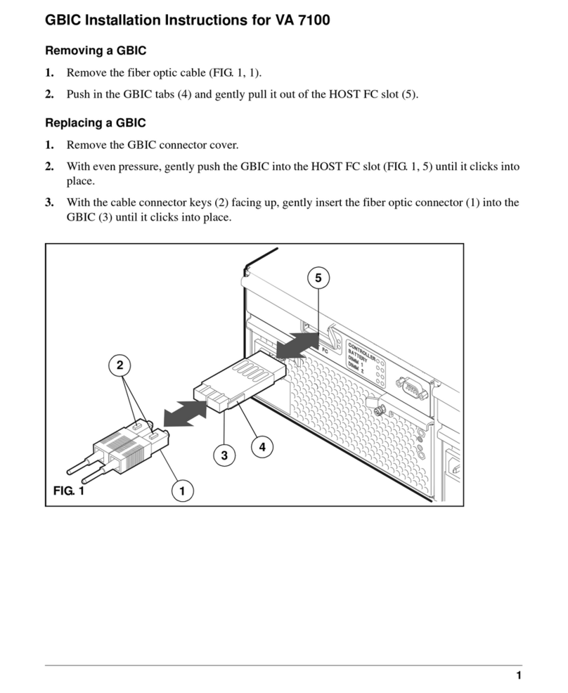
CAUTION: HP LSM drives are not customer installable or replaceable. Any servicing,
adjustment, maintenance or repair must be performed only by authorized HP service-
trained personnel.
Note to Customer Engineer: This installation may add new technology to the library
that older user’s guides do not address. Please remind the customer that the latest user
documentation is available from the HP Customer Care website: http://www.hp.com/go/
support.
■Materials Included
■700 LVD SCSI COMPONENT INSTALLATION
If your library contains the second drive tower, you must first remove the MPM card before
installing the low voltage differential SCSI adapter card. If this does not apply to your
library, skip the following section and begin with MPW card installation, Section B.
A. MPM Removal
1. Be sure that the operator has the library and all drives offline.
2. Open the right front door.
3. Remove power from the library and drives by pushing the main circuit breaker down (off).
4. Using a 3/16 hex driver, remove the customer SCSI Y cable from the MPC card and lower
bulkhead. Discard the cable and the screwlocks that hold the connector to the lower
bulkhead (see Figure 1).
Table 1. Materials List
Part Quantity
I/I CPCI Interface 1
CPCI Card Cage Assembly 1
Cover, EM Module 1
#4-40 x 3/8 Screws 3
#6-32 x 3/8 Screws 8
Terminator 1
SCSI Cable 1
LVD SCSI Icon 1
HP CPCI Interface Kit With LVD SCSI Adapter
Card
(for HP Field Service Use Only)
2
Figure 1.
5. Using a Torx T-15 driver, remove the four Electronics Module (EM) cover screws on the
front and the two on the side and remove the cover (retain screws). Refer to Figure 2.
Figure 2. EM Cover Removal
3
Figure 3. Grating under Electronic Module
WARNING:
THE CURRENT GRATING UNDER THE ELECTRONICS MODULE
ALLOWS SMALL ITEMS (NUMBER 4 SCREWS) TO FALL THROUGH
THE FAN ASSEMBLIES. LIKEWISE, THE GRATING ON TOP OF THE
POWER SUPPLIES (IDENTICAL) WOULD ALLOW SMALL ITEMS
DROPPED FROM ABOVE TO FALL THROUGH AND INTO THE DC
POWER SYSTEM. AT THIS TIME WE ADVISE PLACING A PIECE OF A
CARDBOARD OR AN ESD BAG UNDER THE MPC CONTROLLER
(BOTTOM OF THE ELECTRONICS MODULE) WHILE REMOVING THE
MPM AND WHILE ATTACHING THE CPCI CARD CAGE. BE SURE TO
REMOVE AFTER INSTALLATIONS ARE COMPLETE (SEE FIGURE 3).
4
6. Disconnect the P/J242 and P/J243 connectors from the MPM card. Disconnect cable from
bulkhead (as shown in Figure 4).
Figure 4. MPM Card Components
7. Using a 3/8-in. hex driver, remove the upper and lower MPM card nuts (see Figure 5).
8. Using a Torx T-10 driver, remove the center MPM card screw (see Figure 5).
9. Pull back slightly and turn the card to the left to remove the mounting plate from the two
studs.
10. Remove the MPM card and bracket. Set aside to be reinstalled in Section C.
Figure 5. MPM Card Attach
5
B. MPW Card Installation
If you used Section A to remove the MPM card, skip to Step B5. Otherwise, begin with
Step 1.
1. Open the right front door.
2. Remove power from the library and drives by pushing the main circuit breaker down (off).
3. Remove the customer SCSI Y cable from the MPC card and lower bulkhead. Discard the
cable and the screwlocks that hold the connector to the lower bulkhead (see Figure 1).
4. Using a Torx T-15 driver, remove the four Electronics Module (EM) cover screws on the
front and the two on the side and remove the cover (retain screws). Refer to Figure 6.
Figure 6. EM Cover Removal
WARNING:
THE CURRENT GRATING UNDER THE ELECTRONICS MODULE
ALLOWS SMALL ITEMS (NUMBER 4 SCREWS) TO FALL THROUGH
THE FAN ASSEMBLIES. LIKEWISE, THE GRATING ON TOP OF THE
POWER SUPPLIES (IDENTICAL) WOULD ALLOW SMALL ITEMS
DROPPED FROM ABOVE TO FALL THROUGH AND INTO THE DC
POWER SYSTEM. AT THIS TIME WE ADVISE PLACING A PIECE OF A
CARDBOARD OR AN ESD BAG UNDER THE MPC CONTROLLER
(BOTTOM OF THE ELECTRONICS MODULE) WHILE REMOVING THE
MPM AND WHILE ATTACHING THE CPCI CARD CAGE. BE SURE TO
REMOVE AFTER INSTALLATIONS ARE COMPLETE (SEE FIGURE 7).
6
Figure 7. Grating under Electronic Module
CAUTION: Possible ESD damage. FOLLOW ESD PRECAUTIONS.
5. The card and its card cage are collectively termed “Compact Peripheral Component Inter-
connect”(CPCI). Open the CPCI package and remove the card from the anti-static bag.
6. Remove the MPW card from the CPCI. Loosen the captive screw using a Phillips screw-
driver (see Figure 8).
Figure 8. MPW Card Secure
7
7. Disengage the latch.
8. Gently pull on the MPW card to release it from the MPV connector.
9. Slide the MPW card out of the card cage.
10. Place the MPW card on a static-free surface (you may use the anti-static bag).
CAUTION: Possible equipment damage: PUSH THE MPV CARD STRAIGHT
IN, BEING CAREFUL NOT TO DAMAGE THE CONNECTOR TO THE MPC
CARD.
11. Locate the MPV connector provided on the MPC card at J211. Gently mate the MPV card
with the MPC card connector (see Figure 9).
Figure 9. MPC Card Components
12. Install the three mounting screws (4-40 x 3/8) through the three cutouts in the card cage.
These screws go into the MPC card standoffs (see Figure 10).
Figure 10. CPCI Card Cage
8
CAUTION: Possible ESD damage. FOLLOW ESD PRECAUTIONS.
13. Obtain the MPW card. The MPW card is inserted into the CPCI card cage as described in
the next step.
14. Hold the card so that the card connector aligns with the MPV card connector (circuit side
out, components facing the MPC card).
15. Slide the MPW card onto the guide rail and gently push it until it mates with the MPV card
connector (see Figure 11).
Figure 11. MPW Card Install
16. Make sure the card latch engages (see Figure 8 for Steps 16 and 17).
17. Using a Phillips screwdriver, tighten the captive screw.
Note: If you removed an MPM card, skip to Step 20 otherwise, complete Steps 18
and 19 before proceeding.
18. Remove the ESD bag or cardboard from the grating.
19. Install the new EM cover, using six No. 6-32 x 3/8 screws on the front and two on the side.
NOTE:
ONLY THE LOWER SLOT IS
SUPPORTED AT THIS TIME.
BE SURE TO INSERT THE MPW
CARD INTO THAT SLOT.
9
Note: The library must be at the end of the SCSI bus as shown in Figure 12.
Devices can be host bus adapter, tape drives, other libraries, etc. Figure 12
depicts the actual physical location on the bus and not the SCSI ID.
Figure 12.
20. Connect the feed-through terminator to the connector on the MPW card.
21. Connect the male connector, on the single SCSI cable, to the connector on the feed-
through terminator (see Figure 13).
Figure 13. SCSI Cable Routing
22. Using a 3/16 hex driver, connect the two provided screwlocks through the left side of the
bulkhead into the SCSI cable connector (see Figure 14).
Note: Do not use original screwlocks removed in Step 3. Use the new
screwlocks provided in the kit.
23. Obtain the LVD SCSI icon and place it next to the connector on the bulkhead (see Figure
14).
24. Secure the cable in the strain reliefs.
10
Figure 14.