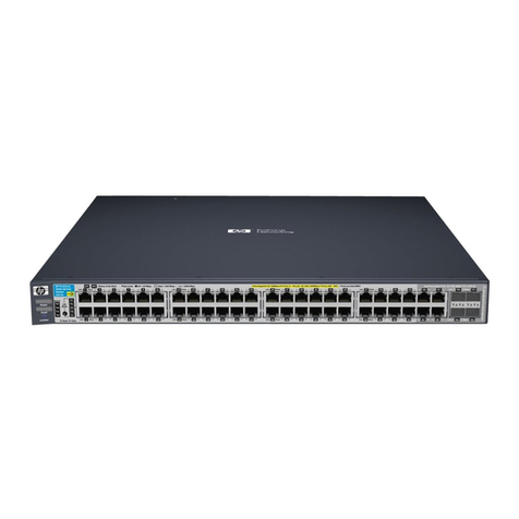
HP invent ProCurve J4908A User manual

-~
ARTISAN
®
~I
TECHNOLOGY
GROUP
Your definitive source
for
quality
pre-owned
equipment.
Artisan Technology
Group
Full-service,
independent
repair
center
with
experienced
engineers
and
technicians
on staff.
We
buy
your
excess,
underutilized,
and
idle
equipment
along
with
credit
for
buybacks
and
trade-ins
.
Custom
engineering
so
your
equipment
works
exactly as
you
specify.
•
Critical
and
expedited
services
•
Leasing
/
Rentals/
Demos
• In
stock/
Ready-to-ship
•
!TAR-certified
secure
asset
solutions
Expert
team
ITrust
guarantee
I
100%
satisfaction
All
tr
ademarks,
br
a
nd
names, a
nd
br
a
nd
s a
pp
earing here
in
are
th
e property of
th
e
ir
r
es
pecti
ve
ow
ner
s.
Find the HP J4908A at our website: Click HERE

www.hp.com/go/hpprocurve
hp procurve switch
gl modules
installation guide


HP ProCurve Switch gl Modules
Installation Guide

© Copyright 2003 Hewlett-Packard Development Company,
L.P.The information contained herein is subject to change
without notice.
This document contains proprietary information, which is
protected by copyright. No part of this document may be
photocopied, reproduced, or translated into another
language without the prior written consent of Hewlett-
Packard.
Publication Number
5990-3090
November 2003
Edition 1
Applicable Products
HP ProCurve Switch 10/100-TX gl Module (J4862B)
HP ProCurve Switch 100/1000-T gl Module (J4863A)
HP ProCurve Switch Gigabit Transceivers gl Module
(J4864A)
HP ProCurve Switch 100-FX gl Module (J4892A)
HP ProCurve Switch mini-GBIC gl Module (J4893A)
HP ProCurve Gig-T/GBIC gl Module (J4908A)
Disclaimer
HEWLETT-PACKARD COMPANY MAKES NO WARRANTY
OF ANY KIND WITH REGARD TO THIS MATERIAL,
INCLUDING, BUT NOT LIMITED TO, THE IMPLIED
WARRANTIES OF MERCHANTABILITY AND FITNESS
FORA PARTICULAR PURPOSE. Hewlett-Packard shall not
be liable for errors contained herein or for incidental or
consequential damages in connection with the furnishing,
performance, or use of this material.
The only warrantiesfor HP products and services are set
forth in the express warranty statements accompanying
such products and services. Nothing herein should be
construed as constituting an additional warranty. HP shall
not be liable for technical or editorial errorsor omissions
contained herein.
Hewlett-Packard assumes no responsibility for the use or
reliability of its software on equipment that is not furnished
by Hewlett-Packard.
Warranty
See the Customer Support/Warranty booklet included with
the product.
A copy of the specific warranty terms applicable to your
Hewlett-Packard product and replacement parts can be
obtained from your HP salesand service office or
HP-authorized dealer.
Hewlett-Packard Company
8000 Foothills Boulevard, m/s 5552
Roseville, California 95747-5552
http://www.hp.com/go/hpprocurve

Contents
Descriptions . . . . . . . . . . . . . . . . . . . . . . . . . . . . . . . . . . . . . . . . . . . . . . . . . . . . 1
Features . . . . . . . . . . . . . . . . . . . . . . . . . . . . . . . . . . . . . . . . . . . . . . . . . . . . . . . . 2
Installing the gl Modules . . . . . . . . . . . . . . . . . . . . . . . . . . . . . . . . . . . . . . . . . . 4
Overview . . . . . . . . . . . . . . . . . . . . . . . . . . . . . . . . . . . . . . . . . . . . . . . . . . . . 4
Installing the Module in an Unused Slot . . . . . . . . . . . . . . . . . . . . . . . . . . 5
Installation Precautions: . . . . . . . . . . . . . . . . . . . . . . . . . . . . . . . . . . . 5
Installation Procedures: . . . . . . . . . . . . . . . . . . . . . . . . . . . . . . . . . . . 5
Installing or Removing the mini-GBICs . . . . . . . . . . . . . . . . . . . . . . . . . . 7
Verifying the Moduleis Installed Correctly . . . . . . . . . . . . . . . . . . . . . . . 8
Connecting the Network Cables . . . . . . . . . . . . . . . . . . . . . . . . . . . . . . . . 9
Verifying the Network Connections Are Working . . . . . . . . . . . . . . . . 12
Customizing the Port Configuration . . . . . . . . . . . . . . . . . . . . . . . . . . . . 13
Replacing orRemoving a Module . . . . . . . . . . . . . . . . . . . . . . . . . . . . . . . . . . 15
Resetting the Switch . . . . . . . . . . . . . . . . . . . . . . . . . . . . . . . . . . . . . . . . . . . . 16
Reasons for Resetting the Switch . . . . . . . . . . . . . . . . . . . . . . . . . . . . . . 16
Methods ofResetting the Switch . . . . . . . . . . . . . . . . . . . . . . . . . . . . . . . 16
Troubleshooting . . . . . . . . . . . . . . . . . . . . . . . . . . . . . . . . . . . . . . . . . . . . . . . . 17
Switch and Module LED Error Indicators: . . . . . . . . . . . . . . . . . . . . . . . 17
Diagnostic Tips: . . . . . . . . . . . . . . . . . . . . . . . . . . . . . . . . . . . . . . . . . . . . . 17
Customer Support Services . . . . . . . . . . . . . . . . . . . . . . . . . . . . . . . . . . . . . . . 21
Specifications . . . . . . . . . . . . . . . . . . . . . . . . . . . . . . . . . . . . . . . . . . . . . . . . . . 21
Environmental . . . . . . . . . . . . . . . . . . . . . . . . . . . . . . . . . . . . . . . . . . . . . 21
Lasers . . . . . . . . . . . . . . . . . . . . . . . . . . . . . . . . . . . . . . . . . . . . . . . . . . . . . 21
Connectors . . . . . . . . . . . . . . . . . . . . . . . . . . . . . . . . . . . . . . . . . . . . . . . . . 22
Twisted-Pair . . . . . . . . . . . . . . . . . . . . . . . . . . . . . . . . . . . . . . . . . . . . 22
Fiber-Optic . . . . . . . . . . . . . . . . . . . . . . . . . . . . . . . . . . . . . . . . . . . . . 22
Cables . . . . . . . . . . . . . . . . . . . . . . . . . . . . . . . . . . . . . . . . . . . . . . . . . . . . . 23
Twisted-Pair . . . . . . . . . . . . . . . . . . . . . . . . . . . . . . . . . . . . . . . . . . . . 23
Fiber-Optic . . . . . . . . . . . . . . . . . . . . . . . . . . . . . . . . . . . . . . . . . . . . . 24
iii

Mode Conditioning Patch Cord for Gigabit-LX . . . . . . . . . . . . . . . . . . . . . . 25
Installing the Patch Cord . . . . . . . . . . . . . . . . . . . . . . . . . . . . . . . . . . . . . 26
Recommended Patch Cords . . . . . . . . . . . . . . . . . . . . . . . . . . . . . . . . . . . 26
EMC Regulatory Statements . . . . . . . . . . . . . . . . . . . . . . . . . . . . . . . . . . . . . . 27
U.S.A. . . . . . . . . . . . . . . . . . . . . . . . . . . . . . . . . . . . . . . . . . . . . . . . . . . . . . 27
Canada . . . . . . . . . . . . . . . . . . . . . . . . . . . . . . . . . . . . . . . . . . . . . . . . . . . . 27
Australia/New Zealand . . . . . . . . . . . . . . . . . . . . . . . . . . . . . . . . . . . . . . . 27
Japan . . . . . . . . . . . . . . . . . . . . . . . . . . . . . . . . . . . . . . . . . . . . . . . . . . . . . . 27
Korea . . . . . . . . . . . . . . . . . . . . . . . . . . . . . . . . . . . . . . . . . . . . . . . . . . . . . . 28
Taiwan . . . . . . . . . . . . . . . . . . . . . . . . . . . . . . . . . . . . . . . . . . . . . . . . . . . . 28
European Community Declaration of Conformity . . . . . . . . . . . . . . . . 28
iv

Descriptions
HP ProCurve Switch gl Modules
For the HPProCurve Series 4100gl Switches
Descriptions. The HPProCurve Switch gl Modules are components that you
can add to an HP ProCurve gl switch to provide a variety of network connec-
tivity options. The following modules are available as of this printing:
Module Description
HP ProCurve Switch
24 twisted-pair ports with RJ-45
10/100-TX gl Module connectors for 10 Mbps or 100
(J4862B)* Mbpsoperation over 100-ohm
unshielded (UTP) or shielded (STP)
twisted-pair cable -- all ports have
the HP Auto-MDIX feature.
HP ProCurve Switch
6 twisted-pair ports with RJ-45
100/1000-T gl Module connectors for 1000 Mbps
(J4863A) (Gigabit) or 100 Mbps operation
over Category 5 orbetter 100-ohm
UTP or STP cable (category 5E
recommended for Gigabit) -- all
ports have the IEEE 802.3ab Auto
MDI/MDI-X feature.
HP ProCurve Switch
Gigabit Transceiver
gl Module (J4864A)
3 transceiver slots for installing
any of the supported HP ProCurve
Transceivers†.
†Supported HP ProCurve Transceivers (as of this printing):
• 100-FX Transceiver (J4853A) • 100/1000-T Transceiver (J4834A)
• Gigabit Stacking Transceiver (part of the HP ProCurve Switch
Gigabit Stacking Kit -- J4116A)
• Gigabit-SX Transceiver (J4131A or J4131B)
• Gigabit-LX Transceiver (J4132A)
HP ProCurve Switch
mini-GBIC gl Module
(J4893A)*
6 mini-GBIC slots for installing any
of the supported HP ProCurve
mini-GBICs**.
** Supported HP ProCurve mini-GBICs (as of this printing):
• Gigabit-SX LC mini-GBIC (J4858A) • Gigabit-LX LC mini-GBIC (J4859A) • Gigabit-LH LC mini-GBIC (J4860A)
* These modules require switch software version G.05.02 or later to be installed in the switch.
Continued on the next page.
1

2
Features
Contact your HP-authorized networking products reseller or your HP repre-
sentative for information on availability of other modules, transceivers, and
mini-GBICs. You can also visit the HP networking products Web site at
http://www.hp.com/go/hpprocurve to get more information.
Features
Example: The HP ProCurve 24-Port 10/100-TX gl Module
HP ProCurve Switch
100-FX MTRJ
gl Module (J4892A)††
12 100-FX ports with MT-RJ
connectors for 100 Mbps
networking over multimode
fiber-optic cable.
HP ProCurve Gig-T/
mini-GBIC gl Module
(J4908A)** ++
20 ports of 10/100/1000Base-T with
2 ports of mini-GBIC gigabit
Ethernet.**.
** Supported HP ProCurve mini-GBICs (as of this printing):
• Gigabit-SX LC mini-GBIC (J4858A) • Gigabit-LX LC mini-GBIC (J4859A) • Gigabit-LH LC mini-GBIC (J4860A)
†† This module requires switch software version G.07.01 or later to be installed in the switch.
++ This module requires switch software version G.07.40 or later to be installed in the switch.
Module Description
retaining screw
network ports
Link and Mode LEDs
(one pair per port)

Features
The HP ProCurve Switch gl Modules have the following features:
■ auto-enabled ports—the ports are all configured to be ready for network
operation as soon as a viable network cable is connected.
■ auto-configuration—a default configuration is applied to the module
when the switch is powered on and the module passes self test; this default
configuration works well for most network installations.
■ LEDs that provide information on the link status, network activity,
connection bandwidth, and communication mode (half or full duplex).
■ “hot swap modules” operation—you can add a module or replace a
module without havingto shut down the switch (changing the module
type in a given slot does require a switch reset).
■ “hot swaptransceivers and mini-GBICs” operation—you can add, replace,
or change the type of any of the transceivers and mini-GBICs that you use
in the Gigabit Transceiver gl Module and mini-GBIC gl Module, without
having to first remove the module, and without having to shut down the
switch.
■ the ports on the 10/100-TX gl Modulehave the HP Auto-MDIX feature,
and the ports on the 100/1000-T gl Module have the IEEE 802.3ab Auto
MDI/MDI-X feature. These features operate the same way and allow you
to use either straight-through orcrossover twisted-pair cables for all the
twisted-pair network connections. Please see the note on “Automatic
Cable Sensing” on page 11.
■ standards adherence:
• the 10/100-TX gl Module is compatible with the IEEE 802.3
10Base-T and IEEE 802.3u 100Base-TX standards
• the 100/1000-T gl Module is compatible with the IEEE 802.3ab
1000Base-T and IEEE 802.3u 100Base-TX standards
• the ports on the transceivers that are installed in the Gigabit Trans-
ceiver gl Module are compatible with their appropriate standards. See
the Installation Guidethe comes with the transceivers.
• the ports on the Gigabit-SX and Gigabit-LX mini-GBICs that are
installed in the mini-GBIC gl Module are compatible with the IEEE
802.3z Gigabit-SX and Gigabit-LX standards respectively.
• the ports on the 100-FX MTRJ gl Module are compatible with the IEEE
802.3u 100-FX standard.
3

Installing the gl Modules
Overview
You can install any of the gl modules into any of the HP ProCurveswitches
that have a compatible module slot. As of this printing, those are the HP
ProCurve Series 4100gl Switches:
■4108gl (p/nJ4865A)
■4108gl Bundle (p/n J4861A)
■4104gl (p/nJ4887A)
■4140gl (p/nJ8151A)
■4148gl (p/nJ4888A) -- a 4104gl bundle
■4160gl (p/nJ8152A)
You can install the modules into the switch either with the switch powered on
or off. The following procedures assume the switch is powered on.
1. Install the modules in a switch slot (see page 5).
If you have installed any modules into slots that were previously occupied
by a different type module, the status LED for the slot will be flashing
indicating that you must reset the switch (see page 16).
2. If you are using the Gigabit Transceiver gl Moduleor the mini-GBIC gl
Module, you can install the transceivers or mini-GBICs in the appropriate
module before or after installing that module into the switch.
Note The HP ProCurve transceivers and mini-GBICs can be“hot swapped”. That is,
they can be installed or removed after the gl Module is installed in the switch
and receiving power.
Please see the Installation Guide thatcame with the transceivers for more
information on installing the transceivers. The information for using the
mini-GBICs is included in this manual (see page 7).
3. Verify the modules are installed correctly (see page 8).
4. Connect the network cabling (see page 9).
5. Optionally, customize the configuration for the modules’ ports (unless the
default port configuration issatisfactory for your network application -
see page 13).
Note If necessary, you can “hot-swap” one module for another; that is, replace one
module with another while the switchis still powered on, without interrupting
the operation of the rest of the switch ports. For more information, see page 15.
4

Installing the gl Modules
Installing the Module in an Unused Slot
Installation Precautions:
■Static electricity can severely damage the electronic components on the modules. When
handling and installing the modules in your switch, follow these procedures to avoid damage
from staticelectricity:
• Handle the module by its bulkhead or edges and avoid touching the components and the
circuitry on the board.
• When installing the module, equalize any static charge difference between yourbody and
the switch by wearing a grounding wrist strap and attaching it to the switch’s metal body,
or by frequently touchingthe switch’s metal body.
■The HPProCurve Switch gl Modules have “low-force”, high-performance connectors.
High insertion forces are not necessary to install the modules, and should not be
used.
■Ensure you fully insert the modules. That is, press the module into the slot until the
bulkhead on the module is contacting or is very close to contacting the front face of the switch
chassis.
■Once the module is fully inserted, ensure you screw in the two retaining screws to secure the
module in place.
■For safe operation, proper switch cooling,and reduction of electromagnetic emissions, ensure
that a slot cover is installed on any unused module slot. For safety, no more than one slot should
be uncovered at a time when the switch ispowered on.
Installation Procedures:
1. Use a Torx T-10 or flat-bladed screwdriver to unscrew the screws in the
cover plate overthe slot you want to use, and remove the cover. Store the
cover plate for possible future use.
2. Holdthe module by its bulkhead—taking carenot to touch the metal
connectors or components on the board.
3. As shown in the illustrations on the next page, insert the moduleinto the
slotguides andslide it into the slot until it stops. Then press near the two
screws on the module bulkhead to seat the module connector into the
switch backplane. The module bulkhead should be incontact with or very
close to contact with the back faceof the switch.
Note: The HP ProCurve Switch gl Modules have “low-force”, high-
performance connectors. High insertion forces are not necessary
to install the modules and should not be used.
5

Installing the gl Modules
1. Insert module into the
guides and slide it in untilit is
fully inserted. “Low-force” connector.
High insertion force is not
needed and should not be
used.
For best results, push
simultaneously near both
screws.
2. Then tightenthe retaining
screws on the module until theyare
secure, but do not overtighten
them.
The module is fully inserted when
the module bulkhead is contacting,
or very close to contacting
the face of the switch.
6

Installing the gl Modules
Installing or Removing the mini-GBICs
You can install orremove the mini-GBIC fromthe mini-GBIC gl Module
without having to power off the switch. Use only HP ProCurve mini-GBICs.
Caution The HP ProCurve mini-GBICs are Class 1 laser devices. Avoid direct eye
exposure to the beam coming from the transmitport.
Installing the mini-GBICs:
Hold the mini-GBIC by its sides and gently insert itinto any ofthe slots in the
module until the mini-GBIC clicks into place.
Removing the mini-GBICs:
You should disconnect the network cable from the mini-GBIC before removing
it from the module.
Depending on when you purchased your HP ProCurve mini-GBICs, itmay have
either of three different release mechanisms: a plastic tab on the bottom of
the mini-GBIC, a wire bail, or a plastic collar around the mini-GBIC.
To remove the mini-GBICs that have the plastic tab or plastic collar, push the
plastic tab or collar toward the switch until you see the mini-GBIC release
from the switch (you can see it move outward slightly), and then pull it from
the slot.
To remove the mini-GBICs that have the wire bail, lower the bail until it is
approximately horizontal, and then using the bail, pull the mini-GBIC from the
slot.
7

Installing the gl Modules
Verifying the Module is Installed Correctly
Observe the Module Status LED for the slot in which the module is being
installed, and the Self Test and Fault LEDs onthe switch to verify the module
is installed properly.
�
Self Test LED Module Status LEDs
Fault LED
Module Link and Mode
LEDs
When the module is installed properly and the switchis powered on, or
the module is installed when the switch already has power, the module
undergoes a self test that takes a few seconds. You can use the LEDs to
determine that the module is installed properly and has passed the self
test, as described in the “LED Behavior” table below.
LED Behavior
LED Display for a Properly Installed Module
Module Status (for the slot in which you are installing the module) Goes ON as soon
as the module is installed and the switch is powered on, and stays
ON steadily.
Self Test ON briefly while the module is being tested, then OFF.
Note: If the switch was powered off while the module was installed,
when the switch is powered on, the Self Test LED will stay ON for
the duration of the self test of the entire switch.
Fault OFF
Link and Mode (on For a module that is installed when the switch is already powered
themodules).Thelink on (hotswap), all the Link and Mode LEDs on the module go ON for
LED lights the port approximately 15 to 20 seconds, then OFF for 5 to 10 seconds
numberand themode dependingon the module. Then, the Self Test LED on the switch goes
LED is next to the port OFF.
number. If the module is already installed when the switch is powered on or
reset, the process described above occurs approximately 30
seconds after the power on or reset, during which the switch is
being tested.
8

Installing the gl Modules
Connecting the Network Cables
Connect the appropriate network cables to the module's ports as shown in
the table below and on the next two pages. More detailed cable information
is included under “Cables” on page 23.
The cabling that you would use for the HPProCurve Gigabit Transceivers that
are installed in the Gigabit Transceiver gl Module depends on the types of
transceivers you are using. Please see the manualthat came with those
transceivers and the informationin this manual on page 23 for information on
the appropriate cabling.
Detailed information on cabling, especially the fiber-optic cabling used with
the Gigabit Transceivers and the mini-GBICs, can be found on the HP
ProCurve web site, http://www.hp.com/go/procurve. Click on Technical
Support and then faqs, and then select the product type.
SupportedCable Types
Module Cable Type Maximum Length
10/100-TX gl Module 10 Mbps operation:
category 3, 4, or 5,
100-ohm differential
100 meters
(recommended)
twisted-pair cable
with RJ-45 connector
RJ-45 ports with
“HP Auto-MDIX”
twisted-pair cable
100 Mbps operation:
category 5, 100-ohm
differential twisted-pair
cable
100 meters
Notes:
• The RJ-45 ports on this module have the HP Auto-MDIX feature. In the module’s default configuration, Auto, either
a straight-through or crossover cable can be used to connect the module to any other 100Base-TX or 10Base-T
device. See the Note on page 11.
• Since the 10Base-T operation is through the 10/100Base-TX ports, if you ever want to upgrade the ports to
100Base-TX, it would be best to cable the ports initially with category 5, or better,cable.
Continued on the next page.
9

10
Installing the gl Modules
Module Cable Type Maximum Length
100/1000-T gl Module 100 Mbps operation:
category 5, 100-ohm
differential twisted-pair
cable
100 meters
1000 Mbps (Gigabit)
operation: category 5E,
100-ohm cable is
recommended, although
category 5 cable may also
work.
100 meters
Note: In the module’s default configuration, Auto, either a straight-through or crossover cable can be used to connect
the module to either another Gigabit device or to a 100Base-T device. See the Note on Automatic Cable Sensing on
page 11.
mini-GBIC gl Module Gigabit-SX operation:
multimode fiber-optic
cables that are fitted with
LC connectors
220 meters to 550
meters, depending on
the cable used. See
“Fiber-Optic Cables”
on page 24 for more
information.
Gigabit-LX operation:
single-mode fiber-optic
cables fitted with LC
connectors.
multimode fiber-optic
cables may also be
used—see “Fiber-Optic
Cables” on page 24.
•single-mode cable:
10 kilometers
•multimode cable:
550 meters
Gigabit-LH operation:
the same single-mode
cables as for Gigabit-LX.
70 kilometers
Notes:
Gigabit-LX – If multimode cable is used, a mode conditioning patch cord may be needed — see “Mode Conditioning
Patch Cord” on page 25 for more information.
Gigabit-LH – Between the transmit and receive ends of the cable, at least 5dB of attenuation is required for a reliable
connection. This is equivalent to 20Km of the fiber-optic cable. For distances less than 20Km, you must add attenuators
to bring the total attenuation to at least 5dB. Most cable vendors carry attenuators.
Continued on the next page.
RJ-45 ports with
“Auto MDI/MDI-X”
twisted-pair
cable with
RJ-45 connector
fiber-optic cable
with
LC connector
Gigabit-LX or Gigabit-SX
mini-GBICs

Installing the gl Modules
Module Cable Type Maximum Length
multimode fiber-optic cable
with MT-RJ connector
100-FX port with
MT-RJ connector
100-FX MTRJ gl Module multimode fiber-optic • full-duplex
cables that are fitted with connections:
MT-RJ connectors. 2 kilometers
• half-duplex
connections:
412 meters
Note Automatic Cable Sensing on Twisted PairPorts:
When the ports for the 10/100-TX gl Module and the 100/1000-T glModuleare
in their default configuration, Auto, both modules automatically negotiate
whether the ports operate as MDI or MDI-X, depending on the cable type and
the connected device’s operation. As a result, you can use either straight-
through or crossover twisted-pair cable for all network connections to these
modules.
On the 10/100-TX gl Module, thisfeature is identified as HP Auto-MDIX; on
the 100/1000-T gl Module, it is identified as Auto MDI/MDI-X and it is part of
the IEEE 802.3ab standard. Both features operate the same.
Operation of this feature depends on the port configurations being kept at
Auto. If the configuration is changed to one of the available fixed options
though (for example, 100-Full Duplex), the port operates as an MDI-X port. In
that case, to connect the module to another switchor hub, use a crossover
cable; to connect to an end node, use a straight-through cable.
11

Installing the gl Modules
Verifying the Network Connections Are Working
Check the port LEDs for the newly-installed module to ensure that the port(s)
connected in the preceding stepare operating correctly.Each port on the
switch modules has Link and Mode LEDs near it as shown in the next
illustration. The Link LED lightsup the port number and the Mode LED lights
up the little white box next to the number.
Example Linkand Mode LEDs
Linkand Mode LEDs
■ The Link LED will be litfor each port that is connected properly to an
active network device.
If the Link LED does not go on when an active network cable is connected
to the port, there may be something wrong with the cable,the cable
connectors, or the deviceat the other end of the cable. See the trouble-
shooting information on page 17.
■ If the switch Mode is set to displayactivity (the
mode indicator LED
is lit), then the Mode LED for each port that is transmitting and/or
receiving packets will flicker when traffic is detected on the port.
■ If the Mode is set to display full duplex (the
mode indicator LED is
lit), then the Mode LED will be lit for each port that is operating in full
duplex.
■ If the Mode is set to display maximum link speed operation (the ï
mode
indicator LED is lit), then the Mode LED will belit for each port that is
operating at its maximum possible link speed. For gigabit-capable ports,
that speed would be 1000 Mbps (Gigabit);for 10/100 ports, that speed
would be 100 Mbps.
12

Installing the gl Modules
Customizing the Port Configuration
If the slotin which you installed the module was empty the last time the switch
was either rebooted or reset (or the power to the switch was cycled), then the
module will use preconfigured default parameter values that will work for
most networks.
The default port configurations for the modules are:
■ Ports Enabled: Yes
■ Mode:
• 10/100-TX gl Module: Auto — The port auto negotiates speed (10 or
100 Mbps), communication mode (half or full duplex), and MDI or
MDI-X port operation. Note: if you configure the port to one of the
fixed 100 Mbps modes, the port will then operate only as an MDI-X
port.
• 100/1000-T gl Module: Auto — The port auto negotiates speed (1000
or 100 Mbps), communication mode (half or fullduplex), and MDI or
MDI-X port operation. Note: if you configure the port to one of the
fixed 100 Mbps modes, the port will then operate only as an MDI-X
port.
• 10/100/1000-T gl Module: Auto —The port auto negotiates speed
(10, 100 or 1000 Mbps), communication mode (half or full duplex),
and MDI or MDI-X port operation. Note: if you configure the port to
one of the fixed 100 Mbps modes, the port will then operate only as
an MDI-X port.
• Gigabit-SX and Gigabit-LX ports in Gigabit Transceiver gl
Module and mini-GBIC gl Module: Auto — The ports always
operate at 1000 Mbps and full duplex. The setting is Auto for best link
establishment with other devices.
• Gigabit-LH ports inthe mini-GBIC gl Module: Auto — The port
always operates at 1000 Mbps and full duplex. The setting is Auto for
best link establishment with other devices.
• 100-FX MTRJ gl Module: 100FDX — The port operates at 100 Mbps
and full-duplex communication mode.
■ Flow Control: Disabled
13
This manual suits for next models
5
Table of contents
Other HP Switch manuals

HP
HP 480-0005-00-15 User manual

HP
HP 2620 series User manual

HP
HP A7533A - Brocade 4Gb SAN Switch Base User manual

HP
HP 316095-B21 - StorageWorks Edge Switch 2/24 User manual

HP
HP 5130 EI Switch Series User manual

HP
HP 263924-002 User manual

HP
HP A5830 Series User manual

HP
HP ProCurve 6208M-SX Manual

HP
HP 6125XLG User manual

HP
HP SN8000B User manual