manuals.online logo
Brands
  1. Home
  2. •
  3. Brands
  4. •
  5. HPE
  6. •
  7. Chassis
  8. •
  9. HPE Altoline 9960 C1 Installation instructions

HPE Altoline 9960 C1 Installation instructions

MF877-00 Page 1
Template Revision A
HPE instructions for this template are available at MF877-01
Product End-of-Life Disassembly Instructions
Product Category: Networking Equipment
Marketing Name / Model
[List multiple models if applicable.]
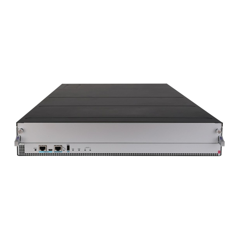
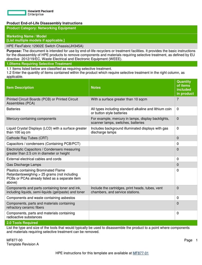
HPE Altoline 9960 C1 8-slot 10RU Chassis (JC910A)
Purpose: The document is intended for use by end-of-life recyclers or treatment facilities. It provides the basic instructions
for the disassembly of HP products to remove components and materials requiring selective treatment, as defined by EU
directive 2002/96/EC, Waste Electrical and Electronic Equipment (WEEE).
1.0 Items Requiring Selective Treatment
1.1 Items listed below are classified as requiring selective treatment.
1.2 Enter the quantity of items contained within the product which require selective treatment in the right column, as
applicable.
Item Description Notes
Quantity of
items
included in
product
Printed Circuit Boards (PCB) or Printed Circuit
Assemblies (PCA)
With a surface greater than 10 sq cm
3
Batteries
All types including standard alkaline and lithium
coin or button style batteries
0
Mercury-containing components
For example, mercury in lamps, display backlights,
scanner lamps, switches, batteries
0
Liquid Crystal Displays (LCD) with a surface
greater than 100 sq cm
Includes background illuminated displays with gas
discharge lamps
0
Cathode Ray Tubes (CRT)
0
Capacitors / condensers (Containing PCB/PCT)
0
Electrolytic Capacitors / Condensers measuring
greater than 2.5 cm in diameter or height
0
External electrical cables and cords
21
Gas Discharge Lamps
0
Plastics containing Brominated Flame Retardants
weighing > 25 grams (not including PCBs or PCAs
already listed as a separate item above)
0
Components and parts containing toner and ink,
including liquids, semi-liquids (gel/paste) and toner
Include the cartridges, print heads, tubes, vent
chambers, and service stations.
0
Components and waste containing asbestos
0
Components, parts and materials containing
refractory ceramic fibers
0
Components, parts and materials containing
radioactive substances
0
MF877-00 Page 2
Template Revision A
HPE instructions for this template are available at MF877-01
2.0 Tools Required
List the type and size of the tools that would typically be used to disassemble the product to a point where components
and materials requiring selective treatment can be removed.
Tool Description
Tool Size (if
applicable)
Phillips screwdriver
#1
Phillips screwdriver
#2
Nut spinner screwdriver
5mm
Nut spinner screwdriver
6mm
Nut spinner screwdriver
10mm
Torx screwdriver
M2.5
3.0 Product Disassembly Process
3.1 List the basic steps that should typically be followed to remove components and materials requiring selective treatment:
1. Remove the PDU module
1. Using a #2 Phillips screwdriver, loose the screws attaching the PDU module.
2. Slide the PDU module off the chassis.
2. Remove the power entry connectors on the PDU module
1. Using a #2 Phillips screwdriver, remove the three M3 screws attaching the power entry connectors.
2. Remove the three power entry connectors and attaching cable.
3. Repeat for the other PDU module.
3. Remove the PDU PCB
1. Using a #2 Phillips screwdriver, remove the three M5 screws on the top of panel and remove the attaching
cables.
2. Using a #2 Phillips screwdriver, remove the three M3 screws attaching the PCB.
3. Remove the PCB and the attaching cable holder.
4. Repeat for the other PDU module.
4. Remove the fan cage
1. Using a #1 Phillips screwdriver, remove 30 screws attaching the fan cage.
2. Slide the fan cage with four fan boards off the chassis.
5. Remove the fan board
1. Using a #2 Phillips screwdriver, remove six M3 screws attaching the fan board.
2. Remove the fan board off the chassis.
3. Repeat for the other three fan boards.
6. Remove the chassis bracket
1. Using a #2 Phillips screwdriver, remove six M3 screws attaching the chassis bracket.
2. Remove the two connector off the bracket.
3. Remove the 8 cable holders off the bracket.
4. Remove the chassis bracket off the chassis.
5. Remove the fan connector.
6. Repeat for the other bracket.
7. Remove the extension busbar
1. Using a #10 nut spinner screwdriver, remove the 8 nuts attaching the extension busbar.
2. Remove the 4 washers.
3. Remove the extension busbar.
4. Repeat for the other bracket.
MF877-00 Page 3
Template Revision A
HPE instructions for this template are available at MF877-01
8. Remove the vertical busbar
1. Using a #2 screwdriver, remove the 8 screws attaching the top and bottom vertical busbar retainer.
2. Using a #6 nut spinner screwdriver, remove the nuts and washers attaching the cable on the vertical busbar.
3. Remove the vertical busbar and retainer.
9. Remove the busbar assembly
1. Using a #2 screwdriver, remove the 6 screws attaching the right and left busbar retainer.
2. Remove the busbar assembly and retainer.
3. Using a #2 screwdriver, remove the 6 nylon screws attaching the busbar assembly.
4. Separate the busbar assembly into two busbar and one mylar.
10. Remove the backplane cable and PDU cable
1. Using a #6 nut spinner screwdriver, remove the 2 nuts attaching the cable.
2. Remove the washers.
3. Repeat for the other 7 backplane cables.
4. Remove the two PDU cables.
11. Remove the whisper cable
1. Using a torx screwdriver, loose the 20 screws attaching the whisper cable.
2. Remove the whisper cable.
3. Repeat for the other whisper cable.
12. Separate the whisper cable
1. Using a #2 screwdriver, remove the 34 screws attaching the whisper cable.
2. Using a 5mm nut spinner screwdriver, remove the 7 spacers attaching the whisper cable.
3. Separate the whisper cable into 10 brackets,10 blocks ,34 screws,7spacers and 4 cables.
4. Repeat for the other whisper cable.
13. Remove the backplane
1. Using a #2 screwdriver, remove the 18 screws attaching the backplane.
2. Remove the backplane.
3. Repeat for the other backplane.
14. Remove the side cover
1. Using a #1 screwdriver, remove the 8 screws attaching the side cover.
2. Remove the side cover.
3. Repeat for the other three side cover.
15. Remove the top cover
1. Using a #1 screwdriver, remove the 2 screws attaching the top cover inside the chassis.
2. Using a #1 screwdriver, remove the 42 screws around the top cover outside the chassis.
3. Remove the top cover.
EL-MF877-00 Page 4
Template Revision B
EL-MF877-00 Page 5
Template Revision B
EL-MF877-00 Page 6
Template Revision B
EL-MF877-00 Page 7
Template Revision B
EL-MF877-00 Page 8
Template Revision B
EL-MF877-00 Page 9
Template Revision B
EL-MF877-00 Page 10
Template Revision B
EL-MF877-00 Page 11
Template Revision B

This manual suits for next models

1

Other HPE Chassis manuals

HPE Synergy 12000 Frame Operating and safety instructions

HPE

HPE Synergy 12000 Frame Operating and safety instructions

HPE 12901E Assembly instructions

HPE

HPE 12901E Assembly instructions

HPE Moonshot 1500 Manual

HPE

HPE Moonshot 1500 Manual

HPE FlexFabric 12902E Assembly instructions

HPE

HPE FlexFabric 12902E Assembly instructions

HPE Apollo k6000 User manual

HPE

HPE Apollo k6000 User manual

HPE Apollo 2000 Gen10 User manual

HPE

HPE Apollo 2000 Gen10 User manual

HPE Synergy 12000 Frame Operating and safety instructions

HPE

HPE Synergy 12000 Frame Operating and safety instructions

HPE Apollo z70 User manual

HPE

HPE Apollo z70 User manual

HPE Apollo 4510 Gen9 Operating and safety instructions

HPE

HPE Apollo 4510 Gen9 Operating and safety instructions

HPE Apollo 4530 Gen9 Operating and safety instructions

HPE

HPE Apollo 4530 Gen9 Operating and safety instructions

HPE StoreEver MSL4048 User manual

HPE

HPE StoreEver MSL4048 User manual

HPE Apollo a6000 Manual

HPE

HPE Apollo a6000 Manual

HPE FF 12904E Assembly instructions

HPE

HPE FF 12904E Assembly instructions

Popular Chassis manuals by other brands

Pentair Schroff 24579-604 user manual

Pentair

Pentair Schroff 24579-604 user manual

Allied Telesis AT-8400 Series installation guide

Allied Telesis

Allied Telesis AT-8400 Series installation guide

MSI VAMPIRIC 010X manual

MSI

MSI VAMPIRIC 010X manual

Philips L01.1L AC Service manual

Philips

Philips L01.1L AC Service manual

IEI Technology EPIC-NANO Series Quick installation guide

IEI Technology

IEI Technology EPIC-NANO Series Quick installation guide

Anritsu MT1810A installation guide

Anritsu

Anritsu MT1810A installation guide

Wyrestorm MX-0808-PP-POH-Custom quick start guide

Wyrestorm

Wyrestorm MX-0808-PP-POH-Custom quick start guide

Uni-Com Media-Chassis/10 FEP-593110 Specifications

Uni-Com

Uni-Com Media-Chassis/10 FEP-593110 Specifications

Multitech CommPlete CC9648 user guide

Multitech

Multitech CommPlete CC9648 user guide

InWin IW-RS316-02M user manual

InWin

InWin IW-RS316-02M user manual

Multitech CommPlete CC9600 user guide

Multitech

Multitech CommPlete CC9600 user guide

TV One ONErack MNL-1RK-CHASSIS v1.10 installation guide

TV One

TV One ONErack MNL-1RK-CHASSIS v1.10 installation guide

Multitech MultiModem ISI5634UPCI-4 reference guide

Multitech

Multitech MultiModem ISI5634UPCI-4 reference guide

Supermicro Supero SC808T-980B user manual

Supermicro

Supermicro Supero SC808T-980B user manual

Advantech HPC-5000 user manual

Advantech

Advantech HPC-5000 user manual

Cabletron Systems MMAC-Plus 6 install guide

Cabletron Systems

Cabletron Systems MMAC-Plus 6 install guide

Intel SC5100 - Server Chassis Rack Optimized Hot Swap Redundant... Product guide

Intel

Intel SC5100 - Server Chassis Rack Optimized Hot Swap Redundant... Product guide

National Instruments cDAQ CALIBRATION PROCEDURE

National Instruments

National Instruments cDAQ CALIBRATION PROCEDURE

manuals.online logo
manuals.online logoBrands
  • About & Mission
  • Contact us
  • Privacy Policy
  • Terms and Conditions

Copyright 2025 Manuals.Online. All Rights Reserved.