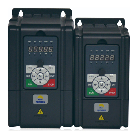
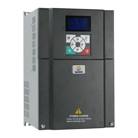
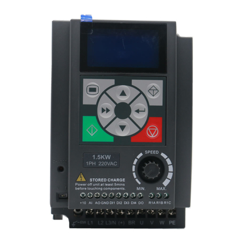
hpmont HD09 Series User manual

V1.1 2018.07
HD09 Series
Smart Inverter
User Manual
Single-phase 220 - 240V, 0.25 - 2.2kW
Three-phase 380 - 460V, 0.4 - 5.5kW

FOREWORD
Thank you for purchasing HD09 series smart inverter manufactured by Shenzhen
Hpmont Technology Co., Ltd.
This User Manual describes how to use HD09 series inverters and their installation
wiring, parameter setting, troubleshooting and daily maintenance etc.
Before using the product, please read through this User Manual carefully. In addition,
please do not use this product until you have fully understood safety precautions.
Note:
Preserve this Manual for future use.
If you need the User Manual due to damage, loss or other reasons, please contact
the regional distributor of our company or directly contact our company Technical
Service Center.
If you still have some problems during use, please contact our company Technical
Service Center.
Due to product upgrade or specification change, and for the purpose of
improving convenience and accuracy of this manual, this manual’s contents may
be modified.
Email address: overseas_1@hpmont.com

Version and Revision Records
Time: 2018/7
Version: V1.1
Revised chapter Revised contents
•Add F04.06 (Integral upper limit), F04.13 - F04.15 (PID regulator)
•F15.19 / F15.20 (DO / Relay function) add: Overload signal (30)
•AddF18.00 (Language selection), F19.38 (Phase short circuit detection action selection),
F20.01 / F20.02 (overload pre-alarm function)

CONTENTS
Chapter 1 Safety Information .................................................................................................................................. 1
Chapter 2 Product Information ............................................................................................................................... 3
2.1 Nameplate .......................................................................................................................................... 3
2.2 Rated Value.........................................................................................................................................4
Chapter 3 Machenical Installation ..........................................................................................................................5
3.1 Dimension and Weight.....................................................................................................................5
3.2 Requirement for the Installation Site............................................................................................. 6
3.3 Installation of Exterior Keypad .......................................................................................................7
Chapter 4 Electrical Installation .............................................................................................................................. 9
4.1 Electric Requirements.....................................................................................................................10
4.2 Power Terminals and Connection .................................................................................................13
4.3 Control Terminals and Connection...............................................................................................14
4.4 External Keypad or Upper Computer...........................................................................................17
Chapter 5 Technical Data .......................................................................................................................................19
5.1 Peripheral Accessories Selection ..................................................................................................19
5.2 Braking Resistor...............................................................................................................................20
5.3 Technical Data..................................................................................................................................21
Chapter 6 Operation................................................................................................................................................23
6.1 Keypad ..............................................................................................................................................23
6.2 Shutdown and Operating Status Parameters.............................................................................25
6.3 Keypad Control Operation.............................................................................................................25
6.4 Terminal Control Running..............................................................................................................26
6.5 Communication Control Operation..............................................................................................26
Chapter 7 Detailed Function Introduction ..........................................................................................................27
7.1 F00: Basic Parameter.......................................................................................................................27
7.2 F01: Parameter Protection function.............................................................................................29
7.3 F02: Start and Stop Controlling Parameter.................................................................................30
7.4 F03: Acceleration and Deceleration Parameter..........................................................................31
7.5 F04: Process PID Controlling Parameter ......................................................................................32
7.6 F05: External Given Curve Parameters.........................................................................................34
7.7 F06: Multistage Speed Function ...................................................................................................35
7.8 F08: Motor Parameter.....................................................................................................................35
7.9 F09: V/f Controlling Parameter......................................................................................................36
7.10 F15: Digital Input / Output Terminals Parameter.....................................................................37
7.11 F16: Analogue Input / Output Terminal Parameter .................................................................44
7.12 F17: SCI Communication Parameter ..........................................................................................45
7.13 F18: Display Control Parameter ..................................................................................................47
7.14 F19: Enhancement Parameters ...................................................................................................48
7.15 F20: Fault Protection Parameter .................................................................................................52
7.16 F23: PWM Controlling Parameter ...............................................................................................53
Chapter 8 Troubleshooting and Maintenance....................................................................................................55
8.1 Troubleshooting ..............................................................................................................................55
8.2 Maintenance.....................................................................................................................................58
Chapter 9 MODBUS Communication Protocol....................................................................................................61
9.1 Overview...........................................................................................................................................61
9.2 Calibration Relationship of Transfer Value Corresponding ......................................................62
9.3 Protocol Functions ..........................................................................................................................62
9.4 Address Mapping Relationship.....................................................................................................65
9.5 Special Instructions.........................................................................................................................67
9.6 Application Examples .....................................................................................................................68
Chapter 10 Parameter.............................................................................................................................................71

Shenzhen Hpmont Technology Co., Ltd. Chapter 1 Safety Information
HD09 Series User Manual V1.1 -1-
Chapter 1 Safety Information
Safety Definition
Pay attention to contents with following marks in the user manual or on the product.
Danger: A Danger contains information which is critical for avoiding safety hazard.
Warning: A Warning contains information which is essential for avoiding a risk of damage to products or other
equipements..
Note: A Note contains information which helps to ensure correct operation of the product.
Professional Staff
Only qualified electrical engineer can perform electrical installation.
Only professional staff that received special training and authorized can carry out maintenances.
Danger
Warning
Note


Shenzhen Hpmont Technology Co., Ltd. Chapter 2 Product Information
HD09 Series User Manual V1.1 -3-
Chapter 2 Product Information
2.1 Nameplate
Nameplate Label
Name plate label is pasted on right side of the product. Its contents are shown in the following figure.
Power Label
Power label is below the keypad for recognizing the products easily and quickly.
Power label includes motor power and supply voltage. See 2.2 Rated Value, page 4.
Its contents are shown in the following figure.
MODEL: HD09-4T0P7G
0.75kW
POWER:
3PH 380-460V 3.4A 50/60Hz
INPUT:
1.5kVA 0-460V 2.3A 0-1000Hz
OUTPUT:
1.00
Version:
Product model
Motor power
Input specification
Output specification
Software version
Serial number
HD09-4T0P7G
Power Label
HD09-2S0P7G
Power Label
Power Label
Motor power
Power voltage

Chapter 2 Product Information Shenzhen Hpmont Technology Co., Ltd.
-4- HD09 Series User Manual V1.1
2.2 Rated Value
Single-phase: 200 - 240V, 50/60Hz
Size Model Motor power
(kW)
Rated input
current (A)
Rated volume
(kVA)
Rated output
current (A)
Size A HD09-2S0P2G 0.25 4.3 0.6 1.7
Size A HD09-2S0P4G 0.4 5.8 1.0 2.5
Size A HD09-2S0P7G 0.75 10.5 1.5 4.0
Size A HD09-2S1P5G 1.5 18.5 2.8 7.5
Size A HD09-2S2P2G 2.2 24.1 3.8 10.0
Three-phase: 380 - 460V, 50/60Hz
Size Model Motor power
(kW)
Rated input
current (A)
Rated volume
(kVA)
Rated output
current (A)
Size A HD09-4T0P4G 0.4 1.8 1.0 1.4
Size A HD09-4T0P7G 0.75 3.4 1.5 2.3
Size A HD09-4T1P5G 1.5 5.2 2.5 3.8
Size A HD09-4T2P2G 2.2 7.3 3.4 5.1
Size B HD09-4T4P0G 4.0 11.9 5.9 9.0
Size B HD09-4T5P5G 5.5 15.0 8.5 13.0

Shenzhen Hpmont Technology Co., Ltd. Chapter 3 Machenical Installation
HD09 Series User Manual V1.1 -5-
Chapter 3 Machenical Installation
•After opening the package, if damage or incompleteness is found, please do not install it and
contact our distributor or us for solutions.
•When conveying the inverter, please employ suitable tools according to its weight. Please avoid
scratch to the product. Be careful: Rollover and drop may cause hurt.
•Avoid scaps of the drill slip into the inverter during installation.
•
For inverter with more than 2 year’s storage, please use regulator to power it slowly.
3.1 Dimension and Weight
Size A:
Dimension: 100 × 150 × 125 mm
Mounting dimension: 82 × 140 mm
Mounting aperture: 5 mm
G.W.: 1.5 kg
Size B:
Dimension: 116 × 185 × 145 mm
Mounting dimension: 98 × 174 mm
Mounting aperture: 6.5 mm
G.W.: 2.7 kg
Danger
82
100 2-Ø5
140
150
125
98
116
2-Ø6.5
174
185
145

Chapter 3 Machenical Installation Shenzhen Hpmont Technology Co., Ltd.
-6- HD09 Series User Manual V1.1
3.2 Requirement for the Installation Site
Ensure the installation site meets the following
requirements:
•Do not install at the direct sunlight, moisture,
water droplet location;
•Do not install at the flammability, explosive,
corrosive gas and liquid locations;
•Do not install at the oily dust, fiber and metal
powder location;
•Be vertical installation on fire-retardant material
with a strong support;
•Install at where the humidity is less than 95%RH
and non-condensing location;
•Install at where the vibration is 3.5m/s2in 2 - 9Hz, 10m/s2in 9 - 200Hz (IEC60721-3-3);
•This inverter meets IP20, and Pollution Degree level 2 (Dry, Non conducting dust pollution);
•Make sure adequate
cooling space for the inverter so as to keep the ambient temperature between
-10 - 40°C, as shown in the figure at the left;
It needs derating use if the inverter operation temperature exceeds 40°C. The derating value of the
output current of the inverter
shall be 2% for each degree centigrade, Max. allowed temperature is
50°C.
≥100 mm
≥100 mm

Shenzhen Hpmont Technology Co., Ltd. Chapter 3 Machenical Installation
HD09 Series User Manual V1.1 -7-
3.3 Installation of Exterior Keypad
HD09 allows installing the optional keypad on the keypad of control door cabinet. The optional
keypads are HD-LED-P and HD-LED-S.
3.3.1 Installation of HD-LED-P
HD-LED-P needs a mounting base HD-KMB for installation. Firstly install the base on the keypad of
control door cabinet, and then install HD-LED-P inside the base.
The HD-KMB base and mounting aperture sizes are shown in the following figure (unit: mm).
3.3.2 Installation of HD-LED-P-S
There are 2 installation methods selectable for HD-LED-P-S: Install with screws or a mounting base.
Packing contents: Mounting base, keypad, 2 pieces of M3x5 screws, 1 meter extension cable.
Installation
Door cabinet
76.5±0.2
134.5±0.2
142
86 44.8
1.8
Mounting aperture sizeHD-KMB size

Chapter 3 Machenical Installation Shenzhen Hpmont Technology Co., Ltd.
-8- HD09 Series User Manual V1.1
To Install with Screws
Install the HD-LED-P-S on the keypad of control door cabinet with screws.
Dimension and mounting aperture sizes are shown in the following figure (unit: mm).
To Install with a Mounting Base
Firstly install the mounting base HD-KMB-S on the keypad of control door cabinet, and then install HD-
LED-S inside the base.
The HD-KMB-S base and mounting aperture sizes are shown in the following figure (unit: mm).
HD-LED-P-S dimension Mounting aperture size
10.7 20
61
2-Ø4
31
20 11.5
25.4
70
40 16.5
32.3
Installation
Door cabinet
Door cabinet
90
74
Mounting aperture size
75.5±0.2
68.5±0.2
19
1.8
Installation
HD-KMB-S size

Shenzhen Hpmont Technology Co., Ltd. Chapter 4 Electrical Installation
HD09 Series User Manual V1.1 -9-
Chapter 4 Electrical Installation
•Only qualified electrical engineer can perform wiring job.
•Only when the power supply switch is completely off can you do the wiring job.
•Check that the operation is effective and reliable after conneting to the emergency stop terminal
of external power supply.
•You must wrap the bare metal part of the power terminal with insulating tape.
•
Do not touch the wire terminals of the inverter when it is live.
Ensure the power supply is completely off
Only when the power supply switch is completely off can you do the wiring job.
Steps:
First, disconnect the power supply of the inverter.
Second, wait till the internal power supply indicator goes out (its position shown in the following
figure) or wait until 5 minutes later.
Danger
Power supply indicator

Chapter 4 Electrical Installation Shenzhen Hpmont Technology Co., Ltd.
-10- HD09 Series User Manual V1.1
4.1 Electric Requirements
4.1.1 Grounding Requirements
Before grounding, the ground terminal of the inverter must be grounded reliably.
There is leakage current to the inverter, ground terminal PE must be grounded, and with the
grounding point as close as possible, grounding area as large as possible, and to ensure that the
grounding resistance is less than 10Ω.
Do not share the ground wire (A) with other power equipment. It is best to have a special grounding
pole (B), but you can also share the ground (C).
If you use several inverters at the same time, you can take a special grounding or common ground way
grounding.
4.1.2 Wiring Requirements
To avoid coupling, the power cables, motor cables and control cables must be installed separately and
ensure a sufficient distance, especially when the cables are installed in parallel and the extension
distance is long.
If the signal cable must pass through the power cable or motor cable, it must pass vertically (90°), as
shown in the following figure.
The power cables, motor cables and control cables should be distributed in different pipelines.
Danger
HD09 Other HD09
PE PE
A. Sharing grounding wire
PE PE
B. Dedicated grounding pole
PE PE
C. Sharing grounding pole
Other HD09 Other
HD09
Power supply cable
Power supply cable
Motor cable
Motor cable
Control cable Control cable
90°
>20 cm
90°
>50 cm
>30 cm

Shenzhen Hpmont Technology Co., Ltd. Chapter 4 Electrical Installation
HD09 Series User Manual V1.1 -11-
4.1.3 Power Cable
•Do not connect the input power cord to the output U / V / W terminal.
•Do not connect the phase-shifting capacitor to the output circuit.
•Make sure that the AC input source voltage matches the rated input voltage of the inverter.
For the selection of the power cable, refer to Section 5.1 Peripheral Accessories Selection, page 19.
4.1.4 Motor Cable
Selection of motor cables, see Section 5.1 Peripheral Accessories Selection, page 19.
The longer the motor cable, the higher the carrier frequency, the higher the harmonic leakage current
on the cable. Leakage current can adversely affect the frequency converter and nearby equipment.
When the motor cable exceeds 100 meters, it is recommended to install the AC output reactor, and
refer to the following table to set the carrier frequency (F23.00).
Motor cable length < 30 m 30 - 50 m 50 - 100 m > 100 m
Carrier frequency setting Below 15 kHz Below 10 kHz Below 5 kHz Below 2 kHz
When the motor cable is too long or the cable cross-section is too large, the derating is reduced by
about 5% for each additional stroke in the recommended cross-sectional area.
Because the larger the cross-sectional area of the cable, the greater the capacitance to ground, the
greater the leakage current.
4.1.5 Control Cable
To reduce the interference and attenuation of the control signal, the length of the control cable should
be limited to 50 meters.
The control cable must be a shielded cable, and the analog signal cable should be twisted shielded.
Shielded cables should use high-frequency low-impedance shielded cables, such as braided copper
mesh, aluminum wire mesh or barbed wire.
Warning

Chapter 4 Electrical Installation Shenzhen Hpmont Technology Co., Ltd.
-12- HD09 Series User Manual V1.1
4.1.6 Leakage protection switch
HD09 inverter built-in EMI filter, the inverter can be connected to the case of power protection can
reduce the external radio frequency interference, while the protection of the ground to produce 10mA
AC leakage current.
In the case of low leakage current applications, the connection between the built-in EMI filter and the
protective ground wire can be disconnected, and the leakage current from the protective ground wire
is less than 1mA AC after disconnection. Disconnect the built-in EMI filter as shown below.
The leakage current protection switch (ELCB / RCD) is installed on the input side of the inverter,
disconnect the built-in EMI filter to prevent mistake action of the ELCB / RCD.
The ELCB / RCD action is related to the fault current waveform it detects, and there are three types:
•AC type: Detects AC fault current and is not suitable for frequency converters.
•Type A: Detects AC fault current and pulsating DC fault current, only applies to single-phase power
input inverter.
•Type B: Detection of AC fault current, pulsating DC fault current and smooth DC fault current, three-
phase power input required that type.
EMI filter connected
(default)
EMI filter disconnected
(dismentle screws)

Shenzhen Hpmont Technology Co., Ltd. Chapter 4 Electrical Installation
HD09 Series User Manual V1.1 -13-
4.2 Power Terminals and Connection
Power Terminal Description
Terminal Description
L1, L2, L3/N Three-phase AC power input
terminals
L1, L3/N One-phase AC power input
terminals
U, V, W Output terminals, connect to
AC motor
(+), BR Braking resistor connection
terminals
PE Ground terminal, connect to
the ground
123
Terminal Description
L1, L2, L3/N Three-phase AC power
input terminals
L1, L3/N One-phase AC power
input terminals
U, V, W Output terminals,
connect to AC motor
(+), BR Braking resistor
connection terminals
(+), (-) DC supply input
terminals
PE Ground terminal,
connect to the ground
L1
Size A:
L2
L3/N
(+)BR
U V W
PE
L1 L2
L3/N
PE
W
VU
BR
(+) (-)
Size B:

Chapter 4 Electrical Installation Shenzhen Hpmont Technology Co., Ltd.
-14- HD09 Series User Manual V1.1
Power Terminal Connection
Power Terminal Wiring is as shown in following figure.
For selection of contactor, MCBB, power supply cable, motor cable, ground cable and braking resistor,
please refer to section 5.1.1 Wiring Specifications of Input and Output, page 19.
4.3 Control Terminals and Connection
Control Terminals Description
Terminal Description
+10 External power Max. output current 100mA
AI
Analogue input
The DIP switch decides the voltage input or current input
•Voltage 0 - 10V, impedance 32kΩ (Factory setting)
•Current 0 - 20mA, impedance 500Ω
Digital input (DI
function)
When AI is used as DI, switch signals above 6V can be received
•Function F15.44 is the same with DI1 - DI3 (F15.00 - F15.02)
AO Analogue output Voltage 0 - 10V
GND Power ground Analogue and digital site, 0V
L1 L2 L3/N (+) BR U V W
Braking resistor*
HD09
MCCB
Contactor
Supply
ground
3~
(-) PE
M
3~
*Braking resisto is
optional three-phase
model type exclusively
+10 AI AOGNDDI1 DI2 DI3 DI4 DO R1A R1B R1C
V I
1
ON
DIP Switch
VI
1
ON

Shenzhen Hpmont Technology Co., Ltd. Chapter 4 Electrical Installation
HD09 Series User Manual V1.1 -15-
Terminal Description
DI1, DI2, DI3 Digital input Effective with GND short circuit
DI4 Digital input
Effective with GND short circuit
or
High frequency input (F15.03 set as No.53 function)
•Max. frequency 50.0kHz (F16.17 setting)
DO Digital output
Open collector output
•External voltage 10 - 30VDC, max. current 50mA
or
High frequency input (F15.19 set as No. 38 function)
•Max. frequency 50.0kHz (F16.26 setting)
R1A, R1B, R1C Relay output •Contact rating: 250VAC / 3A or 30VDC / 1A
•R1B, R1C: Normally closed; R1A, R1C: Normally open
Note:
Limit the current within 3A if the relay terminal is to connect to AC 220V voltage signal.
Control Terminals Connection
The following figure shows wire connection of control terminal (factory setting).
+10
AI
Reference frquency: Refer to F16.19
Frequency setting sources : Refer to F16.01
REV function: Refer to F15.00
REV function: Refer to F15.01
External power: +10V, Max. output current 100mA
Power ground:0V, analogue and digital site
Unused
Inverter is running: Refer to F15.19
Relay output
Inverter fault: Refer to F15.20
AO
GND
DI1
DI2
DI3
DI4
DO
R1A
R1B
R1C
V
Unused
This manual suits for next models
11
Table of contents
Other hpmont Inverter manuals

hpmont
hpmont HD31 Series User manual

hpmont
hpmont HD20 Series User manual

hpmont
hpmont HD09-2S0P2G User manual

hpmont
hpmont HD07-S Series Specification sheet

hpmont
hpmont HD30-2D0P4G 1.0 5.8 2.5 0.4HD30-2D0P7G 1.5 10.5 4.0 0.75HD30-2D1P5G 2.8 18.5 7.5 1.5HD30-2D2P2GHD30-2T3P7G 5.9 19 17... User manual

hpmont
hpmont HD31-4T2P2P User manual

hpmont
hpmont HD3Z Series User manual

hpmont
hpmont HD09-S Series User manual

hpmont
hpmont HD3N Series User manual

hpmont
hpmont HD3N-TC Series User manual