HSC Elite EH1102400W User manual

Control Document No: 00003UIRS0719V1
ELITE IR HEATER –EH1102400W &
EH2402400W
OPERATING INSTRUCTIONS –
PLEASE READ BEFORE USE

Control Document No: 00003UIRS0719V1
Read user instructions
Do Not Cover
Caution: Hot Surfaces
Operating Instructions.
Thank you for purchasing an Elite product, manufactured to a high standard, this product will, if used in
accordance to these operating instructions, labels affixed to the product and properly maintained, provide you
with many years of reliable services.
WARNING!
It is the responsibility of the owner and the operator to read, understand and comply with the following:
You must check all electrical products, before use, to ensure that they are safe. You must inspect power cables,
plugs, sockets and any other connectors for wear or damage. You must ensure that the risk of electric shock is
minimised by the installation of appropriate safety devices.
A Residual Current Circuit Breaker (RCCB) should be incorporated in the main distribution board. We also
recommend that a Residual Current Device (RCD) is used. It is particularly important to use an RCD with
portable products that are plugged into a supply which is not protected by an RCCB. If in any doubt consult a
qualified electrician.
You must also read and understand the following instructions concerning electrical safety.
The Electricity at Work Act 1989 Ed3 requires that all portable electrical appliances, if used on business
premises, are tested by a qualified person, using a Portable Appliance Tester (PAT), at least once a year.
The Health & Safety at Work Act 1974 makes owners of electrical appliances responsible for the safe condition
of those appliances and the safety of the appliance operators. If in any doubt about electrical safety, contact a
qualified electrician.
IMPORTANT: PLEASE READ THESE INSTRUCTIONS CAREFULLY. NOTE THE SAFE OPERATIONAL
REQUIREMENTS, WARNINGS & CAUTIONS.
USE THE PRODUCT CORRECTLY FOR THE PURPOSE TO WHICH IT IS INTENDED.FAILURE TO DO SO
MAY RESULT IN DAMAGE AND/OR PERSONAL INJURY AND WILL INVALIDATE YOUR WARRANTY.
KEEP THESE INSTRUCTIONS SAFE FOR FUTURE USE.

SAFETY.
ENSURE the heater is located on a firm, horizontal dry surface.
ENSURE that the insulation on all cables and on the appliance is safe before connecting it to the power supply.
ENSURE nothing is positioned directly in front or passes by the heater. Maintain a 2 metre exclusion zone
immediately around the front of the heater.
ENSURE the heater is kept clean and in good working order.
ENSURE the heater is in good order and condition before use. If in any doubt do not use the unit and contact
your supplier.
ENSURE the mains cable is free from damage and is not routed on walkways that may present a trip hazard
and potential damage. If any damage is noted replace immediately before use. Use an authorised service agent
only.
ENSURE the heater is cooled before handling or storage.
ENSURE the heater is stored in a safe, dry location preferable in the original packaging if not to be used for a
significant amount of time. Ensure this location cannot be easily accessed by children.
ENSURE Regularly check all connections to ensure that none are loose.
ENSURE that the voltage marked on the appliance matches the power supply to be used and that the plug is
fitted with the correct fuse - see fuse rating.
ENSURE you familiarise yourself with the applications and limitations of the heater before use.
ENSURE the on/off switches are set to “off” before connecting the power.
ENSURE the work area is kept clean and clear of unnecessary items.
ENSURE the heater is disconnect from mains and allow to thoroughly cool before moving, storing or
attempting any cleaning or maintenance.
ENSURE that the element guard is in place, undamaged and firmly attached before use.
ENSURE that only recommended attachments and parts are used. To use unauthorised parts may be
dangerous and will invalidate your warranty.
DO NOT use the heater if any parts are damaged. Immediately remove from service, repair or replace parts.
Use an authorised service agent only.
DO NOT pull or carry the appliance by the power cable
DO NOT pull the plug from the socket by the cable.
DO NOT use worn or damaged cables, plugs or connectors. Immediately have any faulty item repaired or
replaced by a qualified person. When a BS 1363/A UK 3 pin plug or 110V 32A industrial plug is damaged, cut
the cable just above the plug and dispose of the plug safely.
Fit a new plug according to the following instructions.
a) Connect the GREEN/YELLOW earth wire to the earth terminal “E”
b) Connect the BROWN live wire to the live terminal “L”.
c) Connect the BLUE neutral wire to the neutral terminal “N”.
Control Document No: 00003UIRS0719V1

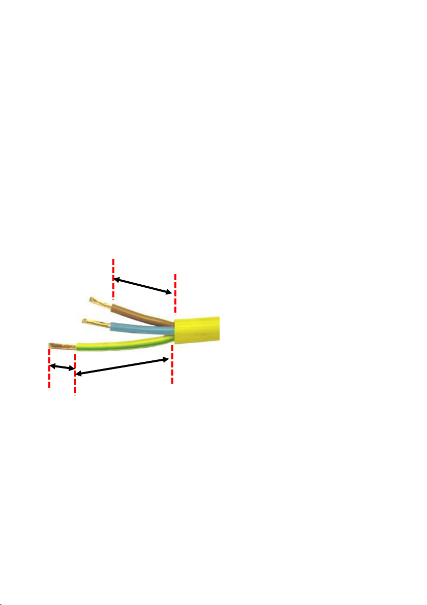
d) After wiring, check that there are no bare wires, that all wires have been correctly connected, that the cable
outer insulation extends beyond the cable restraint and that the restraint is tight.
DO NOT get the heater wet or use in damp or wet locations or areas where there is excessive condensation.
DO NOT locate the heater below a power outlet.
DO NOT touch the heater elements, even when cold.
DO NOT modify the heater or operate a heater which has been modified from its original design.
DO NOT allow untrained persons, children or persons with learning difficulties to operate the heater. Use in a
location where accidental contact (particularly by children) is unlikely.
DO NOT use the heater outside or in a wet environment such as swimming pools
DO NOT operate the heater without any guarding supplied.
DO NOT leave the heater unattended whilst in use.
DO NOT use the heater within a potentially explosive environment
DO NOT use duct work to direct heat. DO NOT restrict air on the inlet or outlet.
DO NOT move whilst on or immediately after switching off.
DO NOT use the heater near flammable, combustible of explosive materials. This may include solids, liquids or
gases. This product gets very hot during use.
DO NOT remove safety guard whilst heater is switched on. Turn off and allow cooling (as above) before
servicing.
DO NOT disassemble the heater for any reason. The heater must be checked by qualified personnel only.
DO NOT use this product to perform a task for which it has not been designed.
DO NOT operate heater without safety guard or elements installed.
DO NOT look directly into the lamps
DO NOT place any object on the safety guard of the heater cassette at any time.
DO NOT use this heater with a programmer, timer or any other device that switches the heater on
automatically since a fire risk exist if the heater is covered or positioned incorrectly.
WARNING! The appliance is not to be used by children or persons with reduced physical, sensory or mental
capabilities or lack of experience or knowledge, unless they have been given supervision or instruction
concerning use of the appliance by a person responsible for their safety. Children should be supervised at all
times to ensure they do not play or touch this appliance.
WARNING! If a fuse blows, ensure it is replaced with an identical fuse type and rating.
AVOIDusing an extension reel. If an extension reel must be used it should be fully unwound before
connection. A reel with an RCD fitted is preferred since any appliance plugged into it will be protected. The
cable core section is important and should be at least 2.5mm @ 240V and 4.0mm @ 110V²
ALWAYS switch off heater, disconnect from power supply and allow cooling for at least one hour before
attempting to touch heater cassette or elements.
Control Document No: 00003UIRS0719V1
²

Getting started
The Elite Heat EH1102400W & EH2402400W is a fully powder coated metal construction heater
using two Quartz Infrared heating lamp providing instant heat when required. Ideal for workshops, garages
and any industrial applications where performance and durability is required.
Features include:
Chemically polished reflectors provide maximum heat
SK15 pre wired elements –essential for portable heaters
Controllable power output comes from the conveniently placed rocker switches on the side of the unit to give
the user control.
Compact design on lockable castors to ensure easy manoeuvrability and safety once positioned.
Ergonomically designed carry handles conveniently located on either side to ensure reduced risk to manual
handling.
Supplied with cable and BS1363 or EN60309 approved plug.
Max.Power: 2400W
Min.Power: 1200W
Input supply: 110V/32A or 240V/13A
Heater Identification Fig.1
1) Handle
2) Heating Lamp
3) Safety Guard
4) Heater Body
5) Castor assembly
6) Power select switches
Inspect your new heater
The package should include the following items which should be removed from the packaging carefully and
inspected for damage;
1X Elite EH1102400W or EH2402400W Radiant Halogen Heater
(with power cord, plug & 2 x 1.2kW infrared halogen heater lamps)
2x castor footplate sub-assemblies
4x M8 x 40mm Hexagonal Bolt to assemble castor footplate sub-assemblies
Assembly
Remove all parts from packaging.
With the main body turned upside down and positioned on flat level surface, it is recommended a
protective cloth/matt is used to prevent damage to the surface finish.
Align castor sub-assemblies ensuring the lockable castor is positioned at the rear of the unit.
Using the bolts provided (M8x40mm hexagonal bolt) secure the sub assembly in position with a
14mm spanner. Tighten to 9 N.m
Repeat on the opposite side of the heater.
Fig.1
Control Document No: 00003UIRS0719V1
1
2
3
4
6
5

Carefully return heater to the upright position.
Your Elite heater EH1102400W & EH2402400W is now ready to use.
Using the Elite Heat EH1102400W EH2402400W
Position the heater in the desired location, please note the following considerations:
Ensure there is a minimum 2M exclusion zone from the front of the heater.
Ensure the heater is not obstructing walkways and the cable is not posing a potential trip hazard.
Ensure there is a suitable power supply to the correct voltage and current available, Check the heaters rating
label for detailed technical information.
Connect to the power supply –before connection ensure the cable and plug are in good condition, free from
any abrasions, cracking or any visual defects. It is also recommended that the lamp power selection switches
are set to off “O” before power is applied.
Select the desired heat output required by switching the switches located on the side of the unit. Note the
upper switch corresponds with the upper lamp, once selected to the one position “1” the switch will now
illuminate and the lamp will turn on. The lower switch corresponds to the lower lamp.
Each lamp is powered at 1200W enabling the heater to be run at either 1200W (1 lamp) or 2400W (2 lamps)
In the event of the heater being knocked over, a safety cut-out switch, which activates at an angle of 35° will
immediately turn both the heater elements off.
Unplug the unit from the power supply
Switch the both lamps to the off position on the switches located on the side of the unit.
Return the heater to a standing position.
Thoroughly visually inspect the heater for damage, making specific attention to the lamps. If there are any
doubts wait for the unit to thoroughly cool and them complete a more detailed inspection.
If no damage has occurred to the elements, re-connect power cord to the power supply and switch the
heater back on.
The infrared element is fragile and therefore it is important that it is not subjected to any unnecessary shocks
or vibration and is not moved when it is on or until cooled down.
The heater can be operated with either one lamp or both lamps illuminated as desired, but ensure both lamps
are fitted at all times.
IMPORTANT: DURING RELOCATION, THE HEATER SHOULD REMAIN SWITCHED OFF AND DISCONNECTED
FROM THE POWER SUPPLY.
IMPORTANT: THE MINIMUM SAFE DISTANCE FOR THE HEATER FROM ANY OBJECT, MATERIAL OR SURFACE
IS 2M. THIS MUST BE ADHERED TO AT ALL TIMES.
Trouble shooting
FAULT DESCRIPTION
SUGGESTED FAULT DESCRIPTION SOLUTION
HEATER DOES NOT OPERATE
Check power supply.
Check for damage or misalignment.
Check all wiring connections
OTHERS
Consult a qualified electrician or dealer.
Control Document No: 00003UIRS0719V1
&

Maintenance
WARNING! There are no serviceable components inside this heater, if any element requires replacing
please consult your supplier and only replace the elements if this can be carried out by a competent person.
The industrial radiant heater is designed and manufactured to withstand tough conditions; this quality product
will give reliable service when periodically cleaned and maintained in accordance with these instructions.
Make sure the heater plug is disconnected from the mains supply before any cleaning or maintenance is
attempted, allow the heater to cool completely.
Do not use water or other liquids, or harsh abrasive cleaners to clean the heater. Clean the exterior with a soft
damp cloth with some mild detergent.
About the Infrared halogen heater lamps
Elite recommends the use of genuine manufacturers Infrared Halogen Heater Lamps for optimum performance
and safety.
Do Not touch halogen lamp quartz glass with bare hands. Quartz tube material could deteriorate by salt and
lose mechanical strength. Sweat on fingers contain salt components and can have detrimental effect on quartz
tubes. Hold the tube using the protective wrapping provided in its package or with a piece of clean dry cloth. If
the tube glass surface is touched, clean cold tube with alcohol and a soft cloth.
Do Not touch a lamp immediately after switching ‘off’ its power supply. Temperature of a halogen lamp
surface can exceed 600°C during its operation. Leave to fully cool for a minimum of 1 hour and remove power
before maintenance.
Technical data
PART NUMBER
110V –EH1102400W
240V –EH2402400W
POWER REQUIREMENT
110V~ or 240V~, 50Hz
INFRARED HALOGEN LAMP
(110V & 240V)
Wattage - 2 x 1.2kW (± 5%)
Overall Length - 300mm
Average Life - 1000Hrs
POWER CORD LENGTH
2 Metres
PLUG
110V - 32A (BS 60309)
240V - 13A UK 3 pin (BS 1363/A) with 13A fuse (BS
1362)
POWER CORD
110V - Black 3G 4.0mm² H07 RN-F
240V - Black 3G 1.5mm² H07 RN-F
DIMENSIONS (LxWxH –Heater cassette in
upright position, inc. castor sub assembly &
handles)
570 x 490 x 870mm (assembled)
580 x 250 x 890mm (packaged)
WEIGHT
15.1Kg (110V) 14.6Kg (240V)
OPERATING TEMPERATURE
-20ºC to +40ºC
Control Document No: 00003UIRS0719V1

Electrical test and storage
WARNING: THIS IS A CLASS 1 TESTED APPLIANCE
When earth bond testing, the readings should be 0.10Ω and below.
Do Not perform a flash test, as this will reduce the life of the heating elements.
When not in use, store the heater carefully in a safe, dry, childproof location. Preferably in the original
packaging if available.
Replacing infra-red halogen heater lamps
Ensure that the replacement lamps are;
the correct voltage rating for the power input i.e. 110V power input –
110V lamp and rated at the correct power, maximum of 1200W
Remove safety guard on front of heater cassette by loosening and removing the two fixing
screws and lifting
guard in an upward direction.
Remove the failed lamps and dispose of in accordance with local waste regulations.
To remove carefully pull out the lamps until clear of the lamp retaining sprung clips.
Once the lamp is clear of the clips gently feed out the fixed wired ends at either side unto the inline connectors
are accessible. Note these are protected by a high temperature silicone cover. Pull apart to expose the inline
clips. Disconnect and dispose of the lamp.
Remove the new tube from outer packaging carefully leaving it in its protective wrapping (see ‘About The
Infrared Halogen Lamps’ and follow the guidance)
To fit the new lamp follow the above in the reverse order. Special attention should be noted to the following;
Ensure
the inline male and female spade connectors are mechanically sound and free of excessive movement
that may lead to high resistance and premature failure
Replace the protective silicone cover fully over the inline connector.
Caution should be observed when feeding the cable back into the main body of the heater. Ensure the cable
does not gather or bunch around the opening.
Gently
push the lamp back onto the sprung clips. These clips should securely hold the lamp in position.
Do not overtighten the screws when refitting the protective safety guard.
ONLY replace the heater elements after ensuring that the heater is NOT plugged in to a power supply.
ONLY replace the heater elements after the heater has had sufficient time to cool down.
DO NOT replace whilst the other elements are still on or had not had sufficient time to cool down.

REPLACEMENT PLUG WIRING INSTRUCTIONS
In the event of the plug requiring re-wiring or replacing, please follow these instructions;
110V –Elite recommend the use of a 32Amp Yellow Plug that conforms to BS 60309.
Unscrew the screws holding the plug rear cover with the yellow plug housing and pull apart.
Loosen the two screws on the strain relief (situated on the rear of the yellow plug housing) to allow
the captive cable to freely move.
Loosen the two screws on each of the conductor pins.
Remove the cable and dispose in accordance with local waste regulations.
Insert a suitable power cord through the rear cover.
Strip the outer power cord insulation approx. 70mm to expose the three cores.
Reduce the live and neutral cores by 10mm to ensure the earth core is 10mm longer.
Strip the insulation of the three cores approx. 10mm to expose the copper conductor strands.
Ensure all copper wire is fully inserted into correct terminal positions before fully tightening all
terminal screws.
Clamp the strain relief over the outer insulation of the power cord (leaving at least 5mm of insulation
above the strain relief on the exposed three cores side) and then fix it in place with the two screws.
Push the plug rear cover together with yellow plug housing and fully tighten with the 2 screws. Do not
over tighten.
Insert the BROWN (live) core into the correct terminal (manufacture symbols may differ) and
loosely tighten both screws.
Insert the BLUE (neutral) core into the correct terminal (manufacture symbols may differ) and
loosely tighten both screws.
Insert the YELLOW/GREEN (earth) core into the correct terminal (manufacture symbols may differ)
and loosely tighten both screws.
240V –Elite recommend the use of a 13Amp UK 3 Pin fused rewire-able plug that conforms to BS 1363/A.
IMPORTANT: IF USING THE 13AMP FUSED PLUG, A 13AMP FUSE, CONFORMING TO BS 1362, MUST BE USED.
•Remove faulty plug from the cable and dispose in accordance with local waste regulations.
•Rewire the plug in accordance with the plugs wiring instructions
Insert the BROWN (live) core into the terminal connected to the fuse housing and finger tighten
screw.
50mm
60mm
10mm
Control Document No: 00003UIRS0719V1

Insert the BLUE (neutral) core into the terminal to the bottom left of the live terminal and finger
tighten screw.
Insert the YELLOW/GREEN (earth) core into the top centre terminal and finger tighten screw.
•Ensure all copper wire is fully inserted into correct terminal positions before fully tightening all terminal
screws.
•Clamp the strain relief over the outer insulation of the power cord and fix in place with the two screws.
Ensure the strain relief is fully positioned onto the outer insulation
•Push the plug rear cover together with plug housing and fully tightened the single centre screw.
If requirement is for a 240V 16Amp or 32Amp Blue Plug, ensure conformity to BS 60309.
For wiring instructions, please follow the applicable 110V wiring instructions where relevant.
Control Document No: 00003UIRS0719V1

ENVIRONMENTAL PROTECTION: Please recycle any unwanted
materials as opposed to disposing them as general waste. It is
recommended the original is retained and used to store the
product when not in use for prolonged periods of time. If this is
not applicable ensure the materials are sorted and recycled in
accordance with local regulations.
SPECIFICATION CHANGE: It is out policy to continually improve products to ensure these meet the
rigours of the industry we serve. Therefore as such we reserve the right to alter specifications, data
and components parts without prior notice.
WARRANTY: All Elite products come with a 1 year warranty from date of purchase, proof of which
will be required in the event of any claim.
IMPORTANT: No liability will be accepted for the incorrect use of this product.
SALES:
Telephone: 0845 3090707
Email: sales@hscuk.co.uk
SPARES:
Telephone: 0845 3090707
Email: spares@hscuk.co.uk
Control Document No: 00003UIRS0719V1
This manual suits for next models
1
Table of contents
Other HSC Heater manuals
Popular Heater manuals by other brands

Toyostove
Toyostove RC-37F Operation and maintenance instructions

Marley
Marley HT2024SSNW instruction manual

ARDES
ARDES AR437A Instructions for use

L.B. White
L.B. White Premier CS700 Owner's manual and instructions

Pro-Elec
Pro-Elec PEL00939 Important safety information

Barton
Barton 96967 Owner's manual and safety instructions

Brava
Brava STELPRO AB41002W owner's manual

Nuaire Group
Nuaire Group AP-EH500-L/RQA9837 installation guide

Sure Flame
Sure Flame IX800 Operation and maintenance manual

Sealey
Sealey IRS153110V instructions

EOS
EOS Vitae Protect+ Compact Installation and operating instruction

Goldair
Goldair PLATINUM GPOC4115 operating instructions