manuals.online logo
Brands
  1. Home
  2. •
  3. Brands
  4. •
  5. HSP
  6. •
  7. Automobile Accessories
  8. •
  9. HSP Premium LID NP25P User manual

HSP Premium LID NP25P User manual

• Pen / Marker • Die Grinder & multi tool • Soapy water solution
• Centre Punch • Masking Tape • Allen Key set (Metric)
• Drill & Drill bits • Scissors & Knife
• Phillips head screwdriver • Ruler
• Caulking Gun • Spanner & Socket
• Silicon - Non Acetic • Tape measure
• Read Instructions fully before commencing installation.
• Clean Tonneau Cover with a mild detergent and water solution
• Do not use abrasive cleaners or solvents
• Refer to manufactures instructions applicable to power drill.
• Protect Tub floor against scratches during installation process.
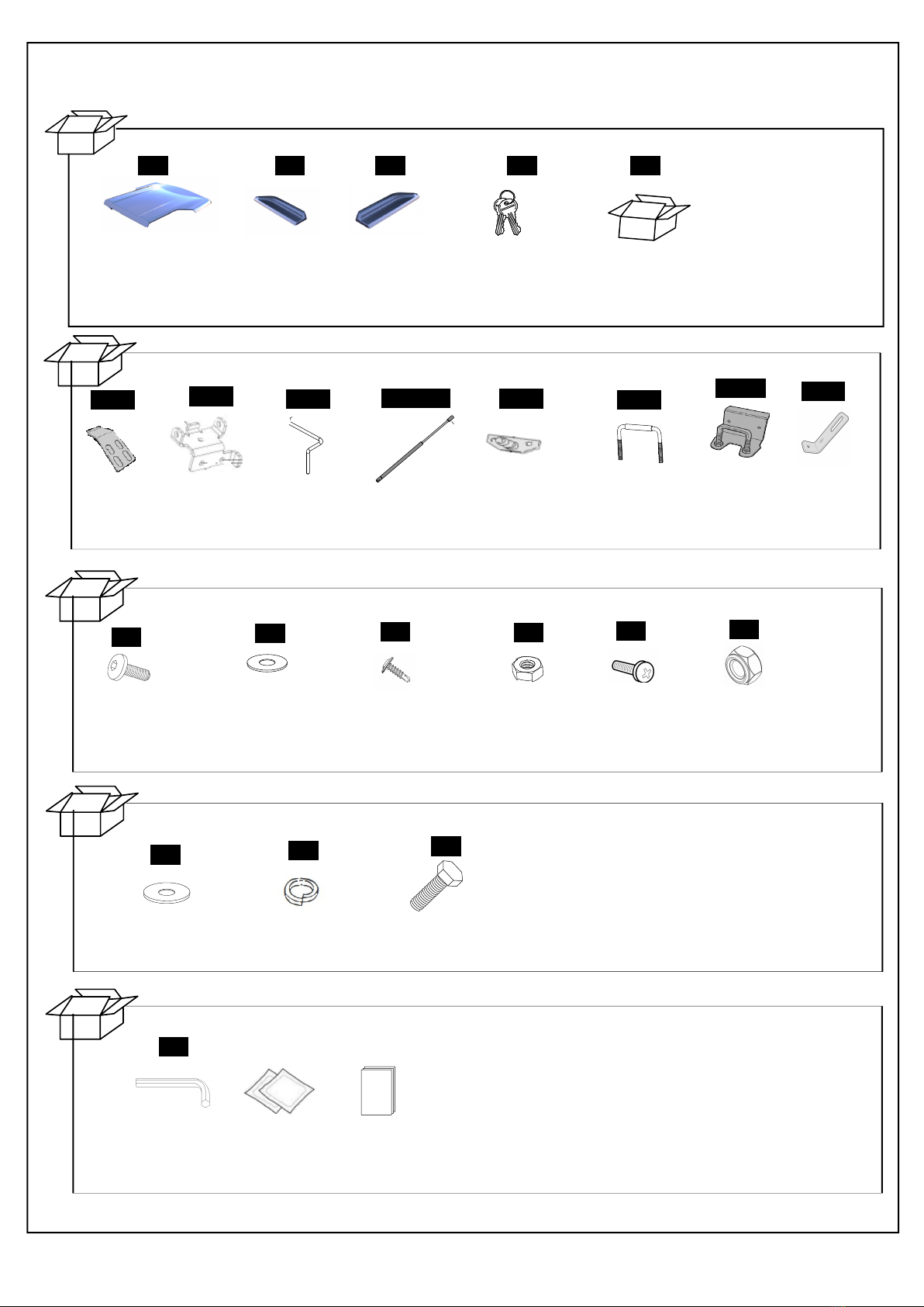
Check contents of kit before commencing fitment and report any discrepancies
Fitting Instructions Part Number NP25P
Nissan NP300 Navara Space Cab 2015+
To suit Sports Bars
If lubrication of the locks or hinges is required use only Graphite Powder. DO NOT use any other
lubricants or oils.
• Do not stand/sit or rest heavy objects on Tonneau Cover
• Humans or animals are not to be under the closed Tonneau at any given time
• Securely lock tonneau Cover before operating vehicle
• Tonneau Cover is not dust or water tight
• Do not carry open volatile chemicals with Tonneau Cover installed
• If contact with volatile chemicals occur, clean Tonneau with mild detergent and water solution
Tools Required
Maintenance
Care Instructions
IMPORTANT
*Image example shown only
NP25P
Page 1 of 20
1
Tonneau Cover
Qty - 1
PARTS IN MAIN CARTON
PARTS IN FITTING KIT
PARTS CHECK SHEET
2 3
Fitting Kit
Qty - 1
4 5
LHS Infill
Panel
Qty - 1
RHS Infill
Panel
Qty - 1
Lock Keys
(Attached to
Tonneau rotery
latch) Qty - 2
OTHER
SPORTSBAR NUT AND BOLTS
Hinge Bracket
Qty - 2
1186
Lid HInge
Qty - 2
Hinge Pin
Qty - 2
Gas Strut
Qty - 2
Strut body mount
Qty - 2
Striker U-Bolt
Qty - 2
Striker
Bracket
Qty - 2
Brace bracket
Qty - 2
42
Alan key
Qty - 1
Fitting
Instructions
Fitting
Instruction
Qty - 1
Alcohol wipe
Qty - 1
1177 1177 S700-220 1040 UB 1189 1200
LID NUTS AND BOLTS
25
M8x25 ALAN
Head Bolt
Qty - 8
24
M8 3mm thick
Flat Washer
Qty - 8
19
Self drilling screws
Qty - 18
M8
Hex Nut
Qty - 8
23
M6 12MM Bolt
Qty - 2
M6 Lock Nut
Qty - 2
115
M6 WASHER
Qty - 4
11
M6 40MM BOLT
Qty - 4
13 18
M6 SPRING WASHER
Qty - 4
NP25P
Page 2 of 20
Installation Steps Flow Chart
START
SPORTS BAR REMOVAL
TUB PREP FOR LID INSTALL
LID INSTALL AND ADJUSTMENT
FINISH
NP25P
Page 3 of 20
Remove Sports Bar from vehicle and retain all hardware.
Thoroughly clean installation areas. Lay a sheet inside the tub to catch metal drill swarf from installation.
NP25P
Page 4 of 20
Drive the self-tapping screws through the holes in the top and the base of the hinge plate into the tub. Tighten
to 3Nm.
Find the centre of the bed and mark the position.
Hinge mounts:
Align the hinge mounts along front of tray, ensuring the hinges are properly positioned from centre of tub 460mm to
centre of hinge mount either side along the inside of the front of tub. Attach the hinges using self-drilling screws
(supplied) through holes pre-drilled into the hinges. Apply clear or black silicone to any gaps and between the hing-
es and the vehicle to prevent water entry.
460mm 460mm
Measure and mark the positions as indicated above from the centre of the bed for placement of the bottom hinges.
WARNING: RECHECK DIMENSIONS TO ENSURE CORRECT MEASURENT
1177
19
NP25P
Page 5 of 20
Gas Struts:
Measure from the front rail inside of tub, measure along top edge of tray 1080 mm (windscreen end) then down
20mm and mark the screws position for the gas strut bracket. Position the gas strut bracket accordingly,
mark two mounting holes and centre. Refer to Fig. 1 and Fig. 2
Fig.1 - Gas strut bracket location
20 mm
Fig.2 - Gas strut bracket location
Using a 2 mm diameter drill bit set to 5 mm drill stop. Drill two pilot holes. Attach small gas strut bracket using self
drilling screws provided. Repeat process on other side of tray. Refer to Fig. 2 and Fig.3
1080 mm
Clean header rail (where extrusion will sit) with alcohol wipes provided and wipe away residue with a dry clean cloth.
Place the extrusion tape seal along the top of the header rail with the sealing lip facing towards the tailgate. Start the
extrusion before the infill ends and run behind the hinges. IMPORTANT: Position extrusion as close to the header rail
rear radius. Rub down firmly to ensure maximum adhesion.
Important:
DO NOT over tighten screws. Recommended tightening torque is 1- 3 Nm
Fig.3 - Gas strut bracket fitment
Attach small shaft end of gas strut onto gas strut brackets, by clicking them in place.
Refer to Fig.4 with regard to gas strut orientation.
Fig.4 - Gas strut orientation
19
S700-220
1040
NP25P
Page 6 of 20
NP25P
Page 7 of 20
18
11
18
11
NP25P
Page 8 of 20
18
11
2
18
11
3
2
NP25P
Page 9 of 20
Important:
Ensure tongues are fully inserted into the hinge slots with hinge pin securely in place.
NP25P
Page 10 of 20
Important:
Ensure tongues are fully inserted into the hinge slots with hinge pin securely in place.
Attach lid hinges to tub hinges
by aligning and pushing pin
through.
Click pin down into hinge
locking tab
1186
Fit the lid and adjust so it is even on
both sides and forward as far as
possible while staying level.
Note: When gas struts are fitted, lid
will be pulled back slightly.
When lid is aligned correctly,
secure the catch hinge to the
lid using 4 M8 Thick
Washers and M8 Bolts
24
25
NP25P
Page 11 of 20
Fig. 9 - Attach gas strut
With the Hard Tonneau Cover opened, attach the cylinder end of each gas strut onto the mounting brackets
attached to the Hard Tonneau Cover by clicking into place
Refer to Fig. 9
Attach the gas struts between
the lid and the mounting brackets.
Important:
If you have purchased a Central Locking Ute Lid please ignore the next page concerning Lock Bracket
Installation and Lock Bracket adjustment.
Lower lid to close position.
Align catch on lid with centre
of latch bar and mark position
of latch on bracket. Repeat
for the opposite side.
1189
NP25P
Page 12 of 20
Fasten latch bracket
in place with self-tapping
screws.
Repeat for the opposite
side.
Self Tapping
Screws
Brace Bracket
12
34
5
Choose relevant hole to
avoid obstruction.
Tighten loosely Align brace bracket against
tub inner wall.
2) Tighten fully
1) Screw in using self drilling screw
Part No: 1200
1
19
15
Part No: 19
1200
NP25P
Page 13 of 20
Cut off excess cable making sure to
leave 20mm from locking allen key bolt.
Loosen 2 screws and slide
catch to align correctly with
latch bar. Tighten screws to
secure in place.
Adjust nuts on latch bar to
alter height of bar to suit.
Repeat for the opposite
side.
Use an Allen key to loosen the hex key
screw on the catch and tension cable
so it is tight but doesn’t move the catch
at all, then re-tighten the hex key screw.
NP25P
Page 14 of 20
NP25P
Page 15 of 20
FIGURE 1
1. Open tonneau cover. Disconnect harness at front
Header bar. Detach gas strut (1) by inserting a small
screwdriver and adjusting the spring clip (2) on the
gas strut(1). Refer to figure 2.
NOTE: Do not remove the spring clip, only a small
amount of levering is required to detach. FIGURE 2
NOTE: 2 people are required to lift and re-
move the tonneau cover from the vehicle.
2. Remove hinge pins (1) and remove tonneau cover (2).
Refer to figure 3.
REMOVAL OF TONNEAU COVER
FIGURE 3
NP25P
Page 16 of 20
FIGURE 4
NOTE: 2 people are required to lift and fit the
tonneau cover onto the vehicle.
1. Fit tonneau cover (2) and secure hinges
with hinge pins (1). Refer to figure 5.
FIGURE 5
2. Attach gas struts (2) by clipping into place. Ensure
narrow end (1) mounts to the vehicle. Reconnect har-
ness at front header bar. Refer to figure 6.
REPLACEMENT OF TONNEAU COVER
FIGURE 6
Having trouble? Call your Supplier.
NOTE: Please ensure Lid is kept locked at all times when not being used, for both safety and longevity.
Paint care instructions:
Your new painted Hard Tonneau Cover has been covered with a plastic film to protect the paint from damage. It will
require cleaning and possibly light polishing after the protective film has been removed. Use polish as per new paint
on a new vehicle. Wash Hard Tonneau Cover using water and normal carwash detergent and polish with an automo-
tive polish.
NP25P
Page 17 of 20
NP25P
Page 18 of 20
NP25P
Page 19 of 20
NP25P
Nissan NP300 Navara Space Cab
NP25P
Page 20 of 20

Other HSP Automobile Accessories manuals

HSP LID-LIGHT-01 User manual

HSP

HSP LID-LIGHT-01 User manual

HSP B15 User manual

HSP

HSP B15 User manual

HSP Tail Lock User manual

HSP

HSP Tail Lock User manual

HSP Roll R Cover Holden Z71 Colorado User manual

HSP

HSP Roll R Cover Holden Z71 Colorado User manual

HSP C25P User manual

HSP

HSP C25P User manual

HSP MX40P User manual

HSP

HSP MX40P User manual

HSP FALCON UTE User manual

HSP

HSP FALCON UTE User manual

HSP ROLL.R.COVER 3 Series Instruction manual

HSP

HSP ROLL.R.COVER 3 Series Instruction manual

Popular Automobile Accessories manuals by other brands

ClipperCreek PEDESTAL installation guide

ClipperCreek

ClipperCreek PEDESTAL installation guide

Trailboss QTMA437 Fitting instructions

Trailboss

Trailboss QTMA437 Fitting instructions

Macally MVENTQI user guide

Macally

Macally MVENTQI user guide

Kia E8300-4D050 manual

Kia

Kia E8300-4D050 manual

Thule Motion XT 6292 instructions

Thule

Thule Motion XT 6292 instructions

Menabo MIZAR Fitting instructions

Menabo

Menabo MIZAR Fitting instructions

Cequent Reese Explore CQT63144 Instruction sheets

Cequent

Cequent Reese Explore CQT63144 Instruction sheets

VBG Onspot Mounting instructions

VBG

VBG Onspot Mounting instructions

Westin 46-20055 instructions

Westin

Westin 46-20055 instructions

Yakima K1043 manual

Yakima

Yakima K1043 manual

ARB AIRLOCKER RD127 installation guide

ARB

ARB AIRLOCKER RD127 installation guide

Shark LED Light Instructions for installation and use

Shark

Shark LED Light Instructions for installation and use

Bilstein E4-WM5-Y558A00 Mounting instruction

Bilstein

Bilstein E4-WM5-Y558A00 Mounting instruction

Prorack K337 Fitting instructions

Prorack

Prorack K337 Fitting instructions

Boyo VTC464RB user manual

Boyo

Boyo VTC464RB user manual

TricLED SLINGSHOT RGB KIT 1 UNDERGROUND HALO manual

TricLED

TricLED SLINGSHOT RGB KIT 1 UNDERGROUND HALO manual

Dakota Digital VHX-69P-GTO Instrument Installation

Dakota Digital

Dakota Digital VHX-69P-GTO Instrument Installation

Response QM-8046 user manual

Response

Response QM-8046 user manual

manuals.online logo
manuals.online logoBrands
  • About & Mission
  • Contact us
  • Privacy Policy
  • Terms and Conditions

Copyright 2025 Manuals.Online. All Rights Reserved.