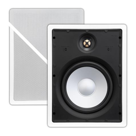
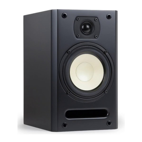
HTD Level TWO Series User manual

Home Theater Direct
Toll free: 866-HTD-AUDIO (483-2834)
www.htd.com
© Copyright Home Theater Direct, Inc.
V.11.30.17
Cabinet Speakers
Owner’s Manual

The amplier that is packaged with the subwoofer in this instruction manual complies with Part 15 of the FCC Rules. Operation
is subject to the following two conditions: (1) this device may not cause harmful interference, and (2) this device must accept any
interference received, including interference that may cause undesired operation.
Safety instructions for the Powered Subwoofer
Warning - To reduce the risk of re or shock, do not expose this appliance to rain or moisture.
Caution - To reduce the risk of re or shock, do not remove the cover or back. No user serviceable parts inside.
Refer servicing to qualied service personnel.
Caution - To prevent electric shock, match wide blade of plug to wide slot, fully insert.
Please read the following warnings and tips before hooking up your HTD Powered Subwoofer:
- Never connect speaker wire or line level connections with the Subwoofer power button in the ON position.
Always make your connections with the amplier OFF.
- Only use the power cord supplied with your HTD Powered Subwoofer.
- Never plug the HTD Powered Subwoofer into the back of another electrical component.
- We highly recommend plugging the HTD Powered Subwoofer into a power tree with surge protection.
CAUTION
RISK OF ELECTRIC SHOCK
DO NOT OPEN
The lightning ash with arrowhead symbol, within an equilateral triangle, is intended to alert the
user to the presence to un-insulated dangerous voltage within the product’s enclosure that may be of
sufcient magnitude to constitute a risk of electrical shock to persons.
The exclamation point within an equilateral triangle is intended to alert the user to the presence
of important operating and maintenance (servicing) instructions in the literature accompanying this
appliance.
Read Instructions
All the safety and operating instructions should be read before
the appliance is operated.
Retain Instructions
The safety and operating instructions should be adhered to.
Heed Warnings
All the warnings on the appliance and in the operating instruc-
tions should be adhered to.
Follow Instructions
All operating and use instructions should be followed.
Water and Moisture
The appliance should not be used near water. For example,
near a bathtub, washbowl, kitchen sink, laundry tub, in a wet
basement, or near a swimming pool, etc.
Ventilation
The appliance should be situated so that its location or position
does not interfere with its proper ventilation. For example, the
appliance should not be situated on a bed, sofa, rug, or similar
surface that may block the ventilation openings: or placed in
a built-in situation, such as a bookcase or cabinet that may
impede the ow of air through the ventilation openings.
Heat
The appliance should be situated away from heat sources
such as radiators, heat registers, stoves, or other appliances
(including ampliers) that produce heat.
Power Sources
The appliance should be connected to a power supply only of
the type described in the operating instructions or as marked
on the appliance.
Grounding or Polarization
Precautions should be taken so that the grounding or polariza-
tion means of an appliance is not defeated.
Power Cord Protection
Power supply cords should be routed so that they are not likely
to be walked on or pinched by items placed on or against them,
paying particular attention to cords at plugs, convenience re-
ceptacles, and the point where they exit from the appliance.
Cleaning
The speaker should be cleaned only as recommended by the
manufacturer.
Power Lines
An outdoor antenna should be located away from power lines.
Non-Use Periods
The power cord of the appliance should be unplugged from the
outlet when left unused for long periods of time.
Object and Liquid Entry
Care should be taken so that objects do not fall and liquids are
not spilled into the enclosure through openings.
Damage Requiring Service
The appliance should be serviced by qualied personnel when:
a) the power supply cord or the plug has been damaged: b)
objects have fallen, or liquid spilled into the appliance: c) the
appliance has been exposed to rain: d) the appliance does
not appear to operate normally or exhibits a marked change
in performance or e) the appliance has been dropped, or the
enclosure damaged.
Servicing
The user should not attempt to service the appliance beyond
that described in the operating instructions. All other servicing
should be referred to qualied service personnel.
Product Servicing
If your system fails to operate properly, please contact HTD
directly for further assistance, at 1-866-483-2834.
1
Thank you for giving Home Theater Direct the chance to win your business! We are condent you will nd
that HTD offers an outstanding combination of performance and value in everything we make. To ensure you get
the most out of your new speakers, please take a moment to read this manual before you get started. Should you
lose this manual, you can always download or print a copy from
www.htd.com.
If you have any questions, we can be reached at...
About HTD and our Cabinet-Style Product Lines
Our mission is to produce home audio products with outstanding performance and build quality that will compete with other systems
costing at least twice as much at retail. We achieve this through exceptional components, many of which are proprietary to HTD, and a
business model that allows us to design, manufacture, and distribute our speakers in the most efcient and cost-effective way possible.
Selling direct also provides close interaction with our customers which gives us a level of insight for improvements and future products
our competitors can’t imagine. At the same time, this close interaction allows us to provide unbeatable personalized service.
All of our cabinet-style speakers include mid-range drivers that include our proprietary FCD cone structure. This is a lightweight, yet
extremely rigid cone that sounds smooth and warm and does not exhibit any of the harshness or ringing often associated with metal
cones. FCD™ stands for Fabric, Ceramic, Doping. A lightweight fabric is used to create the cone’s shape. A ceramic coating is then hand
applied, heated, and hardened to give the cone its stiffness. Finally, a slightly sticky polymer coating (doping) is also hand applied that
helps increase bass response and add warmth to the overall tone. The ceramic and polymer coatings also serve to protect the fabric so
that the speaker will last virtually forever. Bottom line: FCD™ cones are at the heart of the best sounding mid-range drivers we’ve ever
produced.
Our tweeters are made with the nest materials including either hi-grade silk domes or Kapton ribbons, and high efciency Neodymium
magnets. The result is speakers that are clear, detailed, and never harsh sounding. Low and mid-range drivers are blended with the
tweeters using 2nd or 3rd order crossovers that effortlessly transition audio output between components.
Our powered subwoofers include long-throw drivers with doped pulp cones and powerful neodymium magnets. For added bass, we
include an internal transmission line that ends in a front-ring port. Power is supplied via a high-efciency digital amplier built around an
ICEpower™ module developed by Bang and Olufsen and customized for our subwoofers. This amplier is provided separate from the
subwoofer cabinet allowing the exibility to be positioned either with your other audio components or with the subwoofer.
Level THREE Speakers
for dedicated theater
rooms and large living
room theaters.
Level THREE Surround
Sound Speaker
Bi-Pole/Di-Pole Surround Sound Speakers
Level TWO Speakers
for smaller theaters
and most living room
theaters
Speaker Families
DI-POLAR BI-POLAR
DI-POLAR BI-POLAR
DI-POLAR BI-POLAR
DI-POLAR BI-POLAR
Level TWO Surround
Sound Speaker
2

3
About HTD and our Cabinet-Style Product Lines (cont.)
All of our speaker cabinets are cut using computer-managed machines and made of quality 1/2” to 1” MDF with internal bracing to
minimize unwanted cabinet resonance. We never use cheap imitation vinyl wraps, instead our cabinets are painted with mid-gloss
lacquer or expertly covered in gorgeous real wood veneers.
Speaker Placement
Speaker Placement
There is quite a bit of information about speaker placement theory available, but Dolby® (a pioneer in the world of surround sound)
has a really some really helpful information explaining speaker placement in a 5.1 or 7.1 setup. Check out their website if you really
want to dig deeper into this topic.
Basically, the center channel speaker (C) should be as close as possible to
the video screen in order to help “lock” dialogue to an actor’s movements
on screen, and the front left (FL) and front right (FR) speakers should be
placed about 7-15 feet apart for most rooms. Ideally you want the three front
speakers (FL, C, and FR) to be at approximately the same height and distance
from the primary listening spot. This works well with audio-transparent video
screens, but for most other applications you’ll have to compromise a little bit
by placing the Center speaker directly above or below the screen. The key is
to make sure all listening positions have a clear line-of-site to the tweeter. It
is okay for the FL and FR speakers to be placed at a height that is just below
or above the height of the C speaker, but the ideal position is to have all of the
tweeters at approximately ear level.
The two side surround speakers (SL=surround left; SR=surround right) should
be placed to the sides and slightly behind the listening position at a height that
is slightly above ear level. If you are setting up for 5.1, we recommend placing
these speakers approximately 20 degrees behind the listening area. For 7.1 it is
okay to place these speakers only slightly behind the listening area. With 7.1, the
back surround speakers (BL=back left; BR=back right) should be placed behind
the listening area and spread apart about the same amount as the FL and FR
speakers. The subwoofer can be placed almost anywhere in the room because
it is playing frequencies below the point where the human ear and brain can
identify its location. That said, if you have exibility in the location of the powered
subwoofer, we recommend placing it at the front of the room.
Bi-pole/Di-pole
A Di-pole Speaker is one which has matching drivers facing in opposing
directions (approximately 90 degrees) with the drivers on one side ring “out of
phase”. A Bi-pole Speaker physically looks like a Di-pole Speaker but provides a
somewhat less diffuse sound because all the drivers are ring “in phase”.
Placement of Bi-Pole and Di-Pole Speakers is important, as your primary
listening area should generally be
located in what is referred to as
the “Null”. The “Null” is basically an
area where none of the drivers are
directed straight at the listener.
The primary reason for selecting a
Bi-pole or Di-pole speaker design
is to create a more diffuse surround
eld and recreate the ambience
of a larger space or true theater
experience through reected vs.
direct sound.
5.1 Surround
FL CFR
SR
BL
SL
LFE
Screen
Bi-pole/Di-pole 5.1
FL CFR
LFE
Screen
Bi-Pole/
Di-Pole
Bi-Pole/
Di-Pole
7.1 Surround
FL CFR
SR
BRBL
SL
LFE
Screen
Bi-pole/Di-pole 7.1
FL CFR
SL
LFE
Screen
Bi-Pole/
Di-Pole
Bi-Pole/
Di-Pole
Bi-Pole/
Di-Pole
Bi-Pole/
Di-Pole

Connecting the Speaker Cable
HTD BR-TPR and BR-TPRX brackets are a
great solution for wall or ceiling mounting our
Level Two and Level Three bookshelf and
center speakers.
BR-TPR and BR-TPRX brackets must be
anchored to a stud (or similarly reinforced
surface.
BR-TPR and BR-TPRX brackets are
purchased separately from the
speakers.
Speaker stands position your
bookshelf speakers at the proper
listening height. They also add a
touch of elegance and a custom
nish to your home audio system.
Speakers are placed on top of a
wide platform and held in place by
four non-slip pads. Speaker cable
is run up through the bottom of
the stand and through the center
of the post to a hole located just
below the platform. A wide base is
equipped with optional brass tip-
toe feet for decoupling the stand
from its surroundings, and keeping
the stand safely upright.
Our speaker stands are made of
3/4” MDF and nished with a mid-
gloss black lacquer that beautifully
compliments all of our speaker
colors.
Bare Wire with Jumpers
Leave gold-plated jumpers
in place; connect positive
conductor to a red binding
post, negative conductor to
a black binding post. Note
that it is okay to connect to
the top or bottom pair or one
of each.
-
+
-
+
Level TWO
Banana Plug
First, attach cables to banana
plug. Twist binding posts
clockwise before inserting
banana plug to ensure they
are tight.Push banana plug
into binding posts maintain-
ing polarity (plus to plus; mi-
nus to minus).
Open
Closed
4
Bare Wire
Twist binding posts coun-
ter-clockwise to reveal the
“eye”. Insert positive con-
ductor to the red binding
post, negative conductor
to the black binding post.
Twist binding posts clock-
wise to tighten.
Bi-Wire with Banana Plugs
Remove gold-plated jumpers;
top pair of binding posts are for
high frequencies, bottom pair
are for mid-low frequencies.
Level THREE
Gold-plated 5-way binding posts ensure a solid connection
Mounting Options

Connecting the Powered Subwoofer
Our new powered subwoofers include an innovative design that separates the amplier from the subwoofer cabinet. This
allows you to position the amplier anywhere between your home theater receiver and the subwoofer. The amplier is always
connected to the receiver via a shielded powered subwoofer cable using the LFE output on the receiver and the LFE input on
the amplier. The amplier is connected to the subwoofer using regular speaker cable. You will likely place the amplier either
very close to the home theater receiver (Option 1) or very close to the subwoofer (Option 2).
Because shielded cable is more expensive and larger in diameter than most speaker cable, Option 1 is often the most economical
and easiest to install solution. Option 1 also allows you to tweek the amplier settings for the subwoofer from a distance away
from the subwoofer itself. This is benecial because it is difcult to gauge the relative volume of the subwoofer to the other
speakers when you are standing right next to it.
If you have had your room pre-wired, chances are you will need to follow Option 2 because most installers will run a shielded
cable to the subwoofer’s location. This is a more typical arrangement simply because most powered subwoofers on the market
today still have the amplier built into the cabinet. This has been benecial to manufacturers because the cost to add a metal
case to a large analog amplier can be quite expensive. The digital amplier we use is smaller and signicantly more efcient.
The metal case is a minor expense compared to the benets we achieve by not having the amplier built-in. In addition to
increasing installation options, removing the amplier from the subwoofer cabinet provides more volume inside the cabinet and
allows us to add a longer transmission line, both of which enhance deeper bass.
5
-
+
Option 2
Speaker Cable
Home
Theater
Receiver
Shielded powered
subwoofer cable
SDA-200 Digital
Amplier
(not to scale)
Subwoofer Binding Posts
-
+
SDA-200 Digital
Amplier
(not to scale)
Home Theater
Receiver
Shielded powered
subwoofer cable
Speaker Cable
Subwoofer Binding Posts
Option 1

Powered Subwoofer Settings
Power Button, Indicator LED, and Auto-On Switch: When the Power Button is in the out position, the amplier is completely
powered off and the blue Power Indicator LED will be off. Pressing the Power Button in will turn the amplier on if the Auto-On
circuitry is set to “OFF” and the Power Indicator LED will be a bright blue. When the Auto-On circuitry is active (set to “ON”),
pressing in the Power Button will place the amplier in stand-by mode and the Power Indicator LED will be a dim blue. Once a
signal is detected at the LFE input, the amplier will immediately power on and the Power Indicator LED will become bright. After
a signal has not been detected for approximately ten minutes, the amplier will return to stand-by mode.
Protection LED: This LED will light red when there is a fault in the connection to the subwoofer. When this is lit, the power
amplier will not be active until the problem has been resolved. A red light usually indicates a bad cable or connection between
the binding posts on the amplier and the binding posts on the subwoofer.
Phase Switch: The position of this switch will depend on the location of the subwoofer in your room and the acoustical
characteristics of the room itself and the other speakers in the room. For most installations where the subwoofer is located near
the front of the room, this switch should be placed in the 0 position. If the subwoofer is placed in an odd location in the room,
or nearer the back of the room, you may achieve better results by placing this switch in the 180 position. Listen to a stereo
recording with heavy bass to determine which position results in the best blend between the subwoofer and the other speakers
in the room. Bass notes will be slightly punchier when they are correctly in phase with the front three speakers.
Input Level: Set this level one time in order to match the overall volume of the subwoofer with the other speakers in the room.
Again, barring the availability of special test equipment, the best way to do this is by listening to a stereo recording of which you
are very familiar. Once set, the subwoofer volume will move up and down proportionately with the other speakers based on the
volume level of the home theater receiver.
Crossover Control: used to adjust the crossover for the subwoofer and only allow the frequencies you would like the subwoofer
to reproduce when using the “LFE IN XO Active Input” or when using the Speaker Level Input.
LFE Input: Connect a shielded powered subwoofer cable between the LFE input and the LFE output on your home theater
receiver. LFE stands for Low Frequency Effects, and is synonymous with “Subwoofer Line-level Signal”. If you are using the
subwoofer with a stereo receiver and no dedicated subwoofer output is available, simply connect the line level Left and Right
outputs on your stereo receiver to the “L” and “R” Inputs. In this case, make sure you connect to a variable line output on your
receiver. A xed line level output will not work as the volume of the subwoofer will stay constant while the volume of the other
speakers connected to the stereo receiver will move with the volume level of the receiver.
6
POWER
Protect
Subwoofer Digital Amplifier SDA-200
PHASE LEVEL
Min40Hz 120Hz
80Hz
Max
180o
0o
CROSSOVER
SPEAKERS
LFE IN
XO-BYPASSED
R
L
POWER
AMPLIFIER INPUT
SPEAKER OUTPUT
++
--
Auto ON
IR IN
IR IN
Protection LED
LFE Inputs
Speaker Level Input/Output Pass-Thru
Auto-On Switch
Crossover Control
Binding Posts
Power Button Power Indicator LED Input Level
Phase Switch

Binding Posts: Connect speaker cable between these binding posts and the binding posts on the subwoofer. We recommend using
at least 14 gauge cable, although 16 gauge will work for short distances. Bare wire connection is ne, but you can also use spade
connectors or banana plugs. Be sure to maintain polarity between the amplier and the subwoofer, i.e. connect positive to positive and
negative to negative.
Subwoofer Internals
By removing the amplier from inside the subwoofer cabinet, we gain greater volume of air and the ability to extend the internal
transmission line, both of which help extend low bass performance.
Speaker and Subwoofer Settings in Your Home Theater
Receiver
In order for your speakers and subwoofer to work properly for all types of audio
recordings, it is important that you follow the directions for setting up your speakers in
the Owner’s Manual provided by the manufacturer of your home theater receiver. Your
speaker size and subwoofer settings are critical:
Speaker Size: For all but our Tower Speakers, it is best to set the speaker size to
“small”. This will instruct the receiver to direct the lowest frequencies recorded for that
speaker’s channel away from the speaker and into the LFE or Subwoofer output. The
idea is to send the lowest frequencies, which are not directional, into the powered
subwoofer which is best suited for reproducing these super low frequencies. This also
allows the amplier for that channel to be used more efciently across the frequency
range the speaker is best suited to reproduce.
Most home theater receivers allow you to set a frequency point, below which all frequencies are redirected to the subwoofer. You
can experiment with settings of 100 Hz and below with each of our speakers, but you will likely achieve the best performance with the
following settings:
Level THREE: 60 Hz (80 Hz if 60 Hz is not available)
Level TWO: 80 Hz
Subwoofer: Make sure you tell your home theater receiver that your setup includes a powered subwoofer. Believe it or not, some
receivers have the default setting for this set to “no”. You may also be asked if you want the subwoofer to be active for recordings
that do not include a dedicated .1 channel, e.g. stereo. For most listeners, the answer should be “yes”.
Home Theater Direct
Toll free: 866-HTD-AUDIO (483-2834)
www.htd.com
Warranty
All HTD speakers carry a ve-year parts and labor warranty. All HTD electronics
(ampliers, controllers, etc.) carry a two-year parts and labor warranty. Warranty
registration occurred automatically at the time your order was placed. There is no
need to complete or mail in additional paperwork.
Additional information, including detailed specications for each model,
can be found on our website, www.htd.com. Thanks again for choosing Home
Theater Direct!
If you have any questions, we can be reached at...
[email protected] or toll free 1-866-HTD-AUDIO (483-2834)
Diagram depicting internal transmission line of the Level TWO Subwoofer. (drawing
not necessarily to scale and dimensions are subject to change)
This manual suits for next models
1
Table of contents
Other HTD Speakers manuals

HTD
HTD SDX User manual

HTD
HTD Outdoor speakers User manual

HTD
HTD HDX Series User manual

HTD
HTD level two User manual

HTD
HTD Level THREE HTD-R3S User manual

HTD
HTD HTD-W3S User manual

HTD
HTD Level ONE User manual

HTD
HTD Panel/Middy Speaker User manual

HTD
HTD Level THREE User manual

HTD
HTD Cabinet Speakers User manual