manuals.online logo
Brands
  1. Home
  2. •
  3. Brands
  4. •
  5. Huawei
  6. •
  7. Computer Hardware
  8. •
  9. Huawei UPS5000-H-200K-NTJ User manual

Huawei UPS5000-H-200K-NTJ User manual

Without Antiseismic Requirements
Installation Not Against a Wall
Iron bar
Lifting eye
Battery
PE
Mains input
Bypass input
Output
UPS5000-H-200K-NTJ Quick Guide
01 Installing the Cabinet
Model Weight Dimensions (H x W x D)
UPS5000-H-200K-NTJ < 850 kg 2000 mm x 600 mm x 1000 mm
Unpacking
Securing the Cabinet
unit: mm
Issue: 02
Date: 2022-06-20
1. Before installation, read the user manual carefully to get familiar with product information and safety precautions.
2. Use insulated tools when installing the equipment.
3. Only engineers certified by Huawei or its agent are allowed to install, commission, and maintain the UPS. Otherwise,
personal injury or equipment damage may occur, and the resulting UPS faults are beyond the warranty scope.
4. This document describes the installation procedure for a single UPS. For details about how to install a parallel system,
contact Huawei technical support.
1
Space
Planning
Copper Bar Layout and Specifications (unit: mm)
Item
50 kVA
100 kVA
150 kVA
200 kVA
Remarks
Mains input
Mains input current (A)
184
368
553
737
Connection method:
Crimped DT terminal
Bolt Specifications:
R
/S/T/U/V/W/+/-:
M16 x 55 mm (120
N·m)
PE: M12 x 30 mm
(47 N·m)
Equipotential ground point:
M6 x 20 mm
(4.5 N·m)
NOTE:
The currents listed in the
table are measured at a rated
voltage of 200 V. For other
data, see the user manual.
Recommended cross
-
sectional area (mm
2)
R1
100
2 x 100
2 x 200
2 x 250
S1
100
2 x 100
2 x 200
2 x 250
T1
100
2 x 100
2 x 200
2 x 250
PE
38
2 x 38
2 x 100
2 x 150
Bypass input
Bypass input current (A)
144
289
433
577
Recommended cross
-
sectional area (mm
2)
R2
100
2 x 100
2 x 200
2 x 250
S2
100
2 x 100
2 x 200
2 x 250
T2
100
2 x 100
2 x 200
2 x 250
PE
38
2 x 38
2 x 100
2 x 150
Output
Output current (A)
144
289
433
577
Recommended cross
-
sectional area (mm
2)
U
100
2 x 100
2 x 200
2 x 250
V
100
2 x 100
2 x 200
2 x 250
W
100
2 x 100
2 x 200
2 x 250
PE
38
2 x 38
2 x 100
2 x 150
Battery input
(lead
-acid
battery)
Nominal battery discharge
current (A)
225
450
676
901
Maximum battery discharge
current (A)
270
539
809
1079
Recommended cross
-
sectional area (mm
2)
+
2 x 100
2 x 200
3 x 200
4 x 200
-
2 x 100
2 x 200
3 x 200
4 x 200
PE
2 x 38
2 x 100
2 x 150
2 x 200
Battery input
(SmartLi)
Nominal battery discharge
current (A)
104
208
312
416
Maximum battery discharge
current (A)
130
261
391
521
Recommended cross
-
sectional
area
For details, see the IEC
-60364-5-52
specifications and
SmartLi User Manual
.
Equipotential
ground point
Recommended cross
-
sectional
area (mm
2)
16
Installing Lifting Eyes
•Use iron bars with a diameter not
greater than 20 mm to install
lifting eyes.
•For safety, the lifting ropes for
hoisting a cabinet should be able
to withstand a weight that is more
than three times the maximum
weight of the cabinet.
•When hoisting the
UPS, install lifting
eyes on the top of
the cabinet.
•Store the removed
screws. Reinstall
them after hoisting
the cabinet.
M12 bolt
Spring washer
Flat washer
Expansion sleeve
Expansion nut
Concrete floor
With Antiseismic Requirements
Copyright © Huawei Technologies Co., Ltd. 2022. All rights reserved.
M12 bolt
Spring washer
Flat washer
Expansion sleeve
Expansion nut
Concrete floor
M12 bolt
Spring washer
Flat washer
Expansion sleeve
Expansion nut
Concrete floor
02 Installing Cabinets
(Perform this step only when the mains
input and bypass input use different power
sources.) Remove the copper bars between
the mains and bypass input wiring terminals.
Surge protection boxes
Control module
PE
Dry contact extended card
Backfeed protection card
Switch for the top outlet kit
Internal
switch
Installation Against a Wall (with Operation Space on Sides)
Installation Against a Wall
(with Operation Space Only in Front)
2
Verifying the Installation
Without Antiseismic
Requirements
With Antiseismic
Requirements
unit: mm
unit: mm
Without Antiseismic
Requirements
With Antiseismic
Requirements
Monitoring
Interface Card
Ambient
T/H Sensor
Dry Contact
Card
NC connection
NO connection
SmartLi (Master)
Nut Spring
washer
Bolt
Flat
washer
Bypass
module
Power
modules
Battery input Mains
input
Bypass
input UPS output
Signal cable route
Ground bar in the
equipment room
•Different power sources are used as an
example.
•The number and color of signal cables
in the figure are for reference only.
UPS5000-H-200K-NTJ Quick Guide
1. Check that there is no foreign
matter in the cabinet.
2. After routing cables and verifying
cable connections, seal the gap
between cables and the cabinet
using sealing putty. (Remove the
paper protective film from the
sealing putty and retain the
transparent film. When using the
putty, ensure that the transparent
film faces upward.)
3. After verifying the installation,
reinstall all the covers.
4. Do not remove the dust cover
before power-on to prevent dust
from entering the cabinet.
Dust cover
03 Verifying the Installation
Paper
protective
film Sealing putty
Transparent film
Sealing putty must
be used as a whole
and the gap can be
sealed only from the
top.
Bypass input switch
04 Power-On Commissioning
Powering On the UPS
4.1
Turn on the upstream bypass and mains input switches.
After the UPS is powered on, initialization begins. The monitoring display unit (MDU)
displays an initialization progress bar.
1. Before powering on the UPS5000, ensure that the check items in the
UPS5000 Startup
Service Report
and the post-installation check items are verified.
2. Measure the voltage and frequency of the UPS upstream input switch. The line voltage
range is 138–260 V AC, and the frequency range is 40–70 Hz.
Initial Startup
4.2
•If the UPS is powered on for the first time, you need to obtain the startup password from the
Service Expert app. Skip this step if the UPS is not powered on for the first time.
•The Service Expert app can be downloaded from HUAWEI AppGallery and can only run on
Android.
1. Obtain the startup password.
2. Set the language, time, date, network parameters, system parameters, and battery
parameters on the Settings Wizard screen.
Starting the Inverter
4.3
3. After you perform the settings, the Bypass mode and No battery alarms are reported by the
MDU and do not need to be cleared. If there is any other alarm, you need to rectify the fault.
4. If the system has connected to the remote EPO switch, you need to choose Monitoring > UPS
System > Running Parameter > System Settings on the WebUI and set EPO detection to
Enable.
5. View the system running status diagram on the MDU to check that the UPS is working in
bypass mode.
Powering On Loads
4.4
05 Shutting Down the UPS
Set all battery parameters according to the actual situation: Assume that the battery
specifications are 150 Ah/12 V, 40 batteries are connected in series, and two battery strings
are connected to the UPS in parallel. Set Single battery voltage(V) to 12, Single battery
capacity(Ah) to 150, Battery in a battery string to 40, and Number of battery strings to 2.
Download and install the Service Expert app.
After login, tap Power-on password
activation on the screen. A message is
displayed, indicating whether to start the UPS.
Tap OK.
Insert the WiFi module into the USB port on
the MDU. Enable the mobile phone WLAN,
search for the UPS_WIFI signal, and connect to
the WiFi signal. The password is Changeme.
Set the Site and Device Type as required, and
connect the device. Set IP to 192.168.0.10, Port
to 443, Username to admin, Password to
Changeme, and tap Login.
Enter Bar code and Verification code
obtained from the LCD on the Offline
Activation screen. Tap Generate PWD to
generate a startup password.
Set Site and Device Type as required,
and tap Offline Activation.
Enter the generated password in the
password text box on the LCD to start
the UPS.
Use the app to
start the UPS
online?
Yes
No, start
the UPS
offline
On the app home screen, tap StartUp to access the Set Startup screen.
System User LCD Preset
Password
WebUI Preset
Password
admin (system administrator)
000001 Changeme
operator (common user) 000001 Changeme
1. On the main menu, choose Common Functions and tap Inv. ON.
2. In the displayed login window, enter the user name and password, and tap .
3. In the displayed dialog box, tap Yes to start the inverter.
To ensure system security,
change the LCD and
WebUI passwords after
the first login.
1. After the inverter starts, the UPS works in normal mode. The Bypass mode alarm disappears
from the MDU.
2. After confirming that the battery strings are properly connected, turn on the battery string
input circuit breaker. If there are multiple battery strings, turn on the circuit breaker for each
battery string and then turn on the general circuit breaker between battery strings and the
UPS. The No battery alarm disappears from the MDU.
3. Turn on the UPS downstream output switch to supply power to the loads.
After you shut down the inverter, the UPS transfers to bypass mode if the bypass is normal;
the UPS supplies no power if the bypass is abnormal. Before shutting down the UPS, ensure
that all loads have been shut down.
Powering Off a Single UPS
5.2
Shutting Down the Inverter to Transfer the UPS to Bypass Mode
5.1
(Optional) Setting Parameters for the BCB Box
4.5
1. On the main menu of the LCD, choose Common Functions and tap Inv. OFF.
2. In the displayed login window, enter the user name and password, and tap .
3. In the displayed dialog box, tap Yes to shut down the inverter.
If a BCB box is configured, set MUE05A connection to Enable in System Info > Settings > Dry
Contacts Settings, and then set BCB connection [OL] and Battery breaker [STA] to Enable.
Turn off the downstream output switch.
Turn off the bypass input switch QF3.
Turn off the battery string circuit breaker. If there are multiple battery strings, turn
off the general circuit breaker between battery strings and the UPS and then
turn off the circuit breaker for each battery string.
Turn off the upstream mains and bypass input switches.
3
Turn on the top outlet kit switch QF1 and internal switch QF2.
UPS5000-H-200K-NTJ Quick Guide
Turn on the bypass input switch QF3.
Huawei Technologies Co., Ltd.
Huawei Industrial Base, Bantian, Longgang
Shenzhen 518129 People's Republic of China
www.huawei.com

Other Huawei Computer Hardware manuals

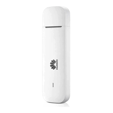
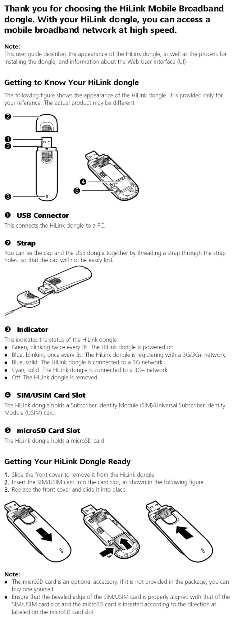
Huawei Mobile Broadband User manual

Huawei

Huawei Mobile Broadband User manual

Huawei UPS5000 User manual

Huawei

Huawei UPS5000 User manual

Huawei NetCol8000-A Series User manual

Huawei

Huawei NetCol8000-A Series User manual

Huawei Telecom Power TP48200A-DT19C2 User manual

Huawei

Huawei Telecom Power TP48200A-DT19C2 User manual

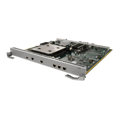
Huawei Quidway S6502 Manual

Huawei

Huawei Quidway S6502 Manual

Huawei RMS-MODBUS01A User manual

Huawei

Huawei RMS-MODBUS01A User manual

Huawei MPUA User manual

Huawei

Huawei MPUA User manual

Huawei RMS-SNMP01B User manual

Huawei

Huawei RMS-SNMP01B User manual

Huawei EM770W User manual

Huawei

Huawei EM770W User manual

Huawei SDongleA-05 User manual

Huawei

Huawei SDongleA-05 User manual

Huawei OptiXstar EG8010Hv6 User manual

Huawei

Huawei OptiXstar EG8010Hv6 User manual

Huawei RT-AR 46-ERPU-1024M User manual

Huawei

Huawei RT-AR 46-ERPU-1024M User manual

Huawei MU709s-2 Installation instructions

Huawei

Huawei MU709s-2 Installation instructions

Huawei SDongleA-03 User manual

Huawei

Huawei SDongleA-03 User manual

Huawei SDongleA-03 User manual

Huawei

Huawei SDongleA-03 User manual

Huawei ME906E Installation instructions

Huawei

Huawei ME906E Installation instructions

Huawei CR-MPUB User manual

Huawei

Huawei CR-MPUB User manual

Huawei EM820W User manual

Huawei

Huawei EM820W User manual

Huawei Wingle Installation guide

Huawei

Huawei Wingle Installation guide

Huawei eMDC610 Technical specifications

Huawei

Huawei eMDC610 Technical specifications

Huawei CR-MPUB User manual

Huawei

Huawei CR-MPUB User manual

Huawei HiLink E303S-1 User manual

Huawei

Huawei HiLink E303S-1 User manual

Huawei MU609 User manual

Huawei

Huawei MU609 User manual

Huawei RRU3908 AC V1 User manual

Huawei

Huawei RRU3908 AC V1 User manual

Popular Computer Hardware manuals by other brands

Lenze MC-PBM Mounting instructions

Lenze

Lenze MC-PBM Mounting instructions

Analog Devices MAX77831 manual

Analog Devices

Analog Devices MAX77831 manual

IEI Technology PEMUX-XEW1 user manual

IEI Technology

IEI Technology PEMUX-XEW1 user manual

YUNEX TRAFFIC ST950SPlus+ Installation and commissioning manual

YUNEX TRAFFIC

YUNEX TRAFFIC ST950SPlus+ Installation and commissioning manual

Penn Elcom FT01-Q-DTC Product data sheet

Penn Elcom

Penn Elcom FT01-Q-DTC Product data sheet

ST STM32F411 user manual

ST

ST STM32F411 user manual

Corsair Hydro Series quick start guide

Corsair

Corsair Hydro Series quick start guide

MYiR MYC-Y335X-V2 product manual

MYiR

MYiR MYC-Y335X-V2 product manual

SIIG NN-000032-S1 Quick installation guide

SIIG

SIIG NN-000032-S1 Quick installation guide

IXIA XRPi2 user guide

IXIA

IXIA XRPi2 user guide

Behringer Ultracurve Pro DEQ2496 quick start guide

Behringer

Behringer Ultracurve Pro DEQ2496 quick start guide

YASKAWA MOTOMAN DX100 instructions

YASKAWA

YASKAWA MOTOMAN DX100 instructions

GOWIN DK START GW1N-LV9EQ144C6I5 V2.1 user guide

GOWIN

GOWIN DK START GW1N-LV9EQ144C6I5 V2.1 user guide

ZyXEL Communications ZyXEL ZyAIR 100 user guide

ZyXEL Communications

ZyXEL Communications ZyXEL ZyAIR 100 user guide

evertz 7800EMR-HYDRA2 user manual

evertz

evertz 7800EMR-HYDRA2 user manual

Delta Electronics DVPAETB-ID32A/OR16A instruction sheet

Delta Electronics

Delta Electronics DVPAETB-ID32A/OR16A instruction sheet

StarTech.com SATABAY3 Instruction guide

StarTech.com

StarTech.com SATABAY3 Instruction guide

Symetrix 528 operating manual

Symetrix

Symetrix 528 operating manual

manuals.online logo
manuals.online logoBrands
  • About & Mission
  • Contact us
  • Privacy Policy
  • Terms and Conditions

Copyright 2025 Manuals.Online. All Rights Reserved.